3D PRINTED PATTERN : AN IN VITRO STUDY
A Diss ertation sub mitted
in parti al fulfil men t of th e requirements
for the degree of
MASTE R O F DENT AL SURGE RY
BRANCH – I
PROSTHO DO NTICS AND CROWN & BRIDGE
THE TAMIL NADU DR.M.G.R. ME DICAL UNI VERS ITY
CHENNAI- 600032
DE PART MENT O F PROSTHO DO NTICS AND CROWN &
BRIDGE
CERTI FICATE
This is to certi f y that Dr.I.EDILBERT RAJA, Post Graduat e student (2014 -2017) in the Departm ent of Prosthodonti cs and crown &
bridge , Adhiparasakthi Dent al Coll ege and Hos pital, M elm aruvathur – 603319, has done this dissertation titled “ ACCURACY O F FIT O F
SCREW RETAINE D IMPLANT SUPE R STRUCT URE CAST FRO M
CONVENT IONAL VS 3D PRINT ED PATTE RN : AN I N VI TRO
STUDY" under our di rect gui dance and supervi sion in part ial
ful film ent of the regul ations laid down by the Tamilnadu Dr.M.G.R Medi cal Universit y, Chennai – 600032 for M DS., (Branch - I) (PROS THODONTIC S AND CR OWN & BR IDGE ) degree exam inati on.
Dr.S.THILL AINAYAGAM MDS.,
Principal
Guide
Dr.A.S.RAMESH MDS.,
Professor & H ead d
Co-Guide
Dr.K.PRABHU MDS.,
ACKNOWLE DGE MENT
I am extremel y grat eful to Dr.A.S.Ramesh MDS., Guide, Professor and Head, Departm ent of Prosthodontics, Adhiparas akthi Dental College and Hospital, Mel maruvathur. Words cannot expres s m y gratitude for his quiet confi dence in m y abilit y to do the stud y, hi s willingness to help t o clear the stum bling blocks along the wa y and hi s tremendous pat ience till the end of t he st ud y.
It is m y dut y t o express m y t hanks to m y Co -Guid e Dr.K.Prabhu MDS., R eader for his expert gui dance and moral support duri ng t he com plet ion of t his st ud y. I consider m ys e lf privil eged, to have studi ed, worked and com plet ed m y diss ert ation under them in the departm ent.
M y sincere thanks t o Dr.S.Thill aina yagam MDS. , our beloved
Principal, Adhiparas akt hi Dent al Col lege and Hos pit al, M elm aruvathur for providing m e wi th the opport unit y t o utiliz e t he faciliti es of the coll ege.
I thank our Corres pondent Dr.T .Ramesh MD., for his vital encouragem ent and s upport .
I am extrem el y thankful t o m y t eachers Dr.N.Venkatesan MDS.,
I am t hankful and express m y gratitude to m y previous t eachers
Dr.Ri jesh MDS., R eader, Dr.Laks mid evi MDS ., Reader, for their
immense help and support for t he initi ati on of t his stud y.
I am extrem el y grat eful to Dr.Shi vaSh ankar MDS., Di rector, Confi dent al l aborat or y,Bengaluru, for grant ing me permission to conduct the s tud y i n his departm ent and helping m e to bri ng out m y stud y.
I thank Dr.Shyam MDS ., S ri venkat eshwara Dental College and hospi tal ,Chennai , for helping m e with the stati sti cs i n the study.
I thank AL MI GHTY GO D for ans weri ng m y pra yers and m aking me what I am toda y.
I owe m y grati tude to m y fat her Mr.K.Iru thayaraj and m y mother Mrs.M.Theresammal who stood besi de wit h st aunch fai th and sacri fi ced s o much t o make m e what I am toda y. I also t ha nk m y l ovi ng sister Dr.I .Geraldin a BDS., for her constant help and encouragem ent throughout m y career.
TIT LE OF THE DIS SERTATION “Accuracy of fi t of screw retained i mplan t su per stru ctu re
cas t f rom conven tional vs 3D
printed pattern - An in vi tro
study”
P LACE OF THE S TUDY Adhi paras akt hi Dent al C oll ege and Hospital, M elm aruvathur – 603319 DUR AT ION OF THE COURSE 3 years
NAM E OF THE GUIDE Dr.A.S .Ramesh MDS ., NAM E OF C O-GU ID E Dr.K.P rabhu M DS.,
I hereb y decl are that no part of the di ss ert ati on will be uti li zed for gai ning financial assist ance or an y promoti on wit hout obt aining prior permi ssion of the Pri nci pal, Adhiparas akthi Dent al C ol lege and Hospital, Mel maruvathur – 603319. In addition, I declare t hat no part of this work wil l be published eit her in print or in el ect ronic medi a without t he gui des who has been acti vel y invol ved i n dis sert ation. The aut hor has the ri ght to res erve for publis h work sol el y with the permiss ion of the Princi pal , Adhi parasakthi Dent al College and Hospital, M elm aruvathur – 603319
Co- G ui de Gui d e & H ead of depart m ent Si gnature of candi dat e
BACKGRO UND:
Accurat e fit of dent al prostheses is thought t o be crit ical to the long -term succes s of t he supporti ng st ruct ures whether thos e st ructures be teeth, mucos a, or i mplants. It had been stated that a passi ve fit of a reconst ruction is im port ant for a ph ys iol og i c tiss ue res ponse and long term os seoint egration of impl ants. Due t o the ank yl oti c charact er of the implants, stres s induced b y a mi sfi t of the s uperstruct ures persist s . Therefore, a pas sive fit of the supers truc tures is des irabl e t o prevent uncont roll ed st ress not onl y i n t he adjacent bone but als o in t he reconst ruction its el f. It has been cl aim ed that s uper s truct ures with a poor fit m a y l ead t o prost heti c compli cations such as looseni ng or fracture of screws, as well as fracture of fram eworks or veneering cerami c and even fractures of abutment s or im pl ant s. During conventional desi gning of patt ern using pat tern wax, stress concent rations occur whi ch lead to dist orted castings. A new method of desi gni ng and m aki ng patt ern using 3D printi ng technology w here thes e stress will be mini mal. M argi nal discrepanc y has been rel at ed to t he preparati on of wax patt ern and defect i n the cas ting process so t he misfit has t o evaluat e using RVG.
AI M:
stud y.
Sel ecti on of experim ent al mo del -com plet el y edent ulous Mandibl e. (1no )
Placem ent of im pl ant s -A B D E positions (from m esi al t o di stal)
Im pression m aki ng.
Fabricati on of m ast er cast .
Wax patt ern of s uperstructure (Convent ional and 3D pri nti ng methods ).
Casti ng of impl ant s uperst ruct ure (C onventional and 3D print ing methods ).
Fabricati on of R adiographi c parall eli ng devi ce .
X-ra ys ( IOP A -Radiovisiograph y) of impl ants with superst ruct ure using radiographi c parall eli ng devi ce .
Evaluat e the standardized radi ographs for pres ence of mi sfit .
Maki ng the m easurement on the radiographs.
Statist ical anal ysi s is used to eval uat e the fit ting of superstruct ure .
RESULTS :
CONCLUS ION:
S.NO TITLE
PAGE
No.
1 INTRODUC TION 1
2 AIM AND OBJ EC TIVES 6
3 REV IEW OF LITER ATURE 7
4 MATER IA LS AND METHODS 35
5 RESULTS 51
6 DISC USS ION 62
7 CONC LUS ION 88
8 REFERENCES 89
FIG.
NO TITLE PAGE No.
1 EXPER IM ENTA L M ODEL-COMP LETE LY
EDENTULOUS M AND IB LE 44
2 EXPER IM ENTA L M ODEL W ITH SURG ICAL
ACRY LIC GUIDE 44
3 IM P LANT KIT 44
4 IN IT IA L LANCE DR ILL 44
5 CHEC KING FOR PARALLE LIS M 44
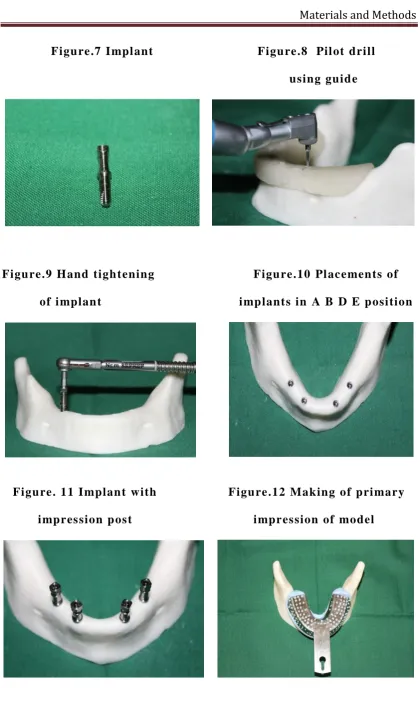
6 IM P LANT 44
7 IM P LANT 45
8 P ILOT DR ILL US ING GU IDE 45
9 HAND T IGHTEN ING OF IMP LANT 45
10 P LACEMENTS OF IMP LANTS IN A B D E
POS IT IONS 45
11 IM P LANT W ITH IM PRESS ION P OST 45
12 MAK ING OF PR IMARY IMPR ESS ION OF M ODEL 45
13 PUTTY IMPR ESS IO N OF THE MODE L 46
14 PR IMAR Y C AST 46
15 FABR IC AT ION OF SPEC IA L TRAY 46
16 OPEN TR AY W ITH SPACER 46
17 OPEN TR AY IN THE M ODEL 46
18 MAK ING IMPR ESS ION W ITH M ED IUM BODY 46
19 SP LIN T ING TO C ONNECT THE P OST 47
20 RES IN TO S TAB ILIZE THE POS T 47
[image:10.595.88.553.121.729.2]23 MASTER C AST W ITH C ASTABLE S LE EVE S 47
24 MASTER C AST W ITH W AX P ATTER N 47
25 MASTER C AST W ITH SPR UE 48
26 MOUNT ING IN C AS TING R ING 48
27 MASTER FR AME WORK 48
28 FR AME WORK IN DUP LIC AT ING BOX 48
29 DUP LIC AT ING S ILICONE W ITH IMPR ESS ION 48
30 DUP LIC ATED W AX PATTER NS 48
31 3D PR INTING M AC HINE 49
32 CAD DATA 49
33 3-D PR INTED RES IN PATTERN 49
34
3D PR INTED P ATTERN IN EXPER IM ENTAL MODEL
49
35 FR AME WORK IN EXPER IMENTAL MODEL 49
36 FR AMEW ORKS 49
37
MAK ING OF X R AY W ITH P ARA LLE LING DEVIC E
50
38 RVG IM AGE 50
[image:11.595.88.550.66.769.2]TABLE.
NO
TITLE
PAGE No.
1 M IS FIT M EAS UREMENT OF GR OUP I 53
2 M IS FIT M EAS UREMENT OF GR OUP II 54
3
STAT IST IC AL ANALYS IS IS US ED TO EVALUATE THE F ITTING OF
SUPERSTR UCTURE IN POS IT ION A
55
4
STAT IST IC AL ANALYS IS IS US ED TO EVALUATE THE F ITTING OF
SUPERSTR UCTURE IN POS IT ION B
56
5
STAT IST IC AL ANALYS IS IS US ED TO EVALUATE THE F ITTING OF
SUPERSTR UCTURE IN POS IT ION D
57
6
STAT IST IC AL ANALYS IS IS US ED TO EVALUATE THE F ITTING OF
SUPERSTR UCTURE IN POS IT ION E
58
7 OVERA LL MEAN VALUES 59
GRAPH.NO TITLE PAGE No.
1 THE MEASURED DIS CREP ANC Y VA LUES
60
2 COMPAR IS ON OF MEAN
61
LIST OF FLOW CHARTS
CHART.NO TITLE PAGE No.
1
B IO LOGIC AND MECHANIC AL IM P LA NT COMP LIC AT IONS
63
2
THE D ISTORT ION EQUATION AND IT S RELAT IONSH IP TO THE M IS F IT
RVG-R adiovisi ograph y RP- R api d prot ot ypi ng PU – Pol y uret hane W/P – Wat er/Power ratio
KA L - kulzer Abut m ent Lut ing
CAD-CAM – comput er aided desi gn – comput er ai ded m anufacturing 3D- print ing – Three dim ensi onal pri nting
UC LA abut ments – Universit y of C ali fornia abutm ent s EDM –El ect rical dis charge m achine
INTRODUCTION
Treatment options for repl acem ent of missing t eeth have trul y evolved from anci ent tr ans plant to modern da y impl ants -The Thi rd Dentition. Impl ant s have revolut ioniz ed dental practi ce and have hel ped to overcom e m an y of the li mitati ons encount ered wit h conventional fixed or removabl e prosthesis and is considered as an aestheti c, functional restoration wit h l ong -term predictabilit y.1
The impl ant -abutment connection is a joint c onsi sting of 2 part s hel d together wit h a screw. The function of the s crew is to creat e a cl amping force bet ween the impl ant and abutment suffi ci ent t o withs tand external loads .1 Screw retenti on in impl ant -support ed prosthesis was devel oped in response to t he need for ret ri evabilit y even though occl usion and aestheti cs were s acri fi ced. There is almost no tolerance for error i n the fabri cation of the screw ret ained prost hesis becaus e a di rect m etal -to -m etal connecti on exists and there are man y vari abl es not in t he control of the doct or.2 Becaus e t here is no space bet ween the coping and impl ant abutment , the cas ting must fi t com plet el y pas sivel y and accurat el y before the screw is ins ert ed wit h a considerable torque force.1
oss eoint egration o f implants. Due t o the ank yl oti c charact er of the implants, st ress i nduced b y a mi sfi t of t he super st ructures persist s.3
In im plant s upport ed prosthes is, mi nim izing st ress along t he implant and surrounding bone is a desired feature. Thi s could be possi ble t hrough a passi ve fit of the prosthesis ’ superst ructure on the implant abutm ents .
A fram ework i s considered passi ve when there is simultaneous circular cont act of all the prostheti c cyl i nders with thei r respective implant abutm ents .4 Therefore, a passiv e fit of the s uperst ructures is desi rabl e t o prevent uncont rol led st ress not onl y i n the adj acent bone but als o in the restoration its el f.5 , 6
Achieving a pas si ve fit between im plant frameworks and underl yi ng st ruct ures is ess ential for s uccess ful long t erm oss eoint egration.8 If a pas sive fit i s not achi eved,
1. Il l fitting implant fram ework ma y caus e mechani cal fail ures of the prosthes es , impl ant s yst ems, or biologi c compli cations of the surroundi ng t issue.
2. Mechani cal com pli cations m a y include loosening of the prosthethesi s and abutment screws or fract ure of vari ous com ponent s in the s ystem .
3. Biologi c com pli cat i ons m a y i ncl ude advers e tis sue reacti ons, pai n, t endernes s, m arginal bone los s, and loss of integrati on.8
Stefania C. Kano et al. proposed a cl as sifi cation for the implant -abutm ent i nterface includes both horizont al and verti cal
com ponent s.9
T ype I: No horizontal or verti cal gap could be m easured (horizontal -A = 0 and verti cal -B = 0). Thi s cl ass was considered ideal.
T ype II: Onl y horiz ont al mis fit was obs erved; t he abutm ent was either undercontoured (B < 0) or over contoured (B > 0).
T ype III: Onl y verti cal mi sfi t (A > 0) was obs erved.
Sci enti fi c evidence is l acki ng t o demonst rat e the need of a pas sive-fitti ng prost hesi s for long -t erm osseoint egration.1 2
During conventional desi gning of patt ern using patt ern wax, stress concent rations occur whi ch l ead to distort ed cas tings .1 3 , 1 4 Inherent i n l aborator y cast ing procedures are dis torti ons and irregul ari ties that ma y affect the fit and functi on of t he impl ant restoration. Inves ti gators have studi ed the impact of thes e casti ng errors on screw j oint int egrit y. C ast i ng procedures decrease t he percentage of appli cation torque and that machined abutm ent s retai ned si gni fi cantl y great er det orque values com pared t o cast abutments.1 3
AIM AND OBJECTIVES
REVIEW OF LITERATURE
Bran emark et al (1985 )1 0 st at ed that Trul y pas sive
screw -ret ained pros thes is are virt ual l y im possi bl e to fabri cat e Branemark to be ideall y in the 10 µm range. Becaus e there i s no space bet ween the coping and impl ant abutment , the cas ting must fi t com plet el y pas sivel y and accurat el y before the screw is ins ert ed wit h a considerable torque force.
R.A. E rikss on et al (1986 )1 7 stat ed that t he t em peratures eli ci ted
duri ng drilling accordi ng to t he osseoint egrat ion technique wer e measured in vivo i n five edentul ous hum an m andibl es. The temperature changes were meas ured b y a therm ocoupl e, the tip of whi ch was situated 0.5 mm form the dril l surface and s eparat ed from it by a corti cal wall. Ei ghteen m easurem ent s showed a mean initi al temperature of 29.2°C before drilli ng and a mean maximum temperature of 30.3° C duri ng dri lling. The maximum temperature recorded was 33.8°C . The duration of t he maximum temperatures neve r exceeded 5 seconds. All temperat ures recorded were below the l evel for im paired bone regenerat ion. It was concl uded that drilling according t o th e oss eoint egration t echnique does not caus e an y impai red bone regenerati on becaus e of excessive heat producti on.
Patri ck J. Hen ry et al (1987 )2 8 st at ed t hat The precis ion of fit
distribut e functional stress es over the indi vidual impl ant s over the long term. This is parti cularl y im portant in t he m axil lar y prosthesi s where a proper st ress dist ribution i s criti cal to avoid t he ris k of dest ro yi ng an est abli shed oss eoi nt egration of the fixtures. Ext rem e requi rement s for the fit ting of t he prosthesis to t he abutm ents must be mai nt ai ned at all times , and the occlusion must be carefull y adjus ted: “Atraum ati c surger y must be foll owed b y at raum ati c prosthodont ics. ”
Mark R. Sp ector et al (1990 )5 2 s tat ed t hat M easurable
distortions resulted from t he t rans fer of impl ant positions as recorded with three im pres s ion techniques. (technique I, gui de pi n -ret ai ned trans fer copings were united with aut o pol ym erizi ng acr yl ic resin and dental floss . t echnique II, a pol yvi n yl sil oxane impressi on was m ade in a stock tra y over h ydrocol loid t ransfer copings. In the thi rd t echni que, a condens ation sili cone impression was made in a stock t ra y over h ydrocoll oid t rans fer copi ngs)The magnitude of the dist orti ons were similar wi th all three techniques evaluat ed. In addit ion to di mens ional changes in the m at erials us ed, positi onal errors were al so att ribut ed t o the m echani cal com ponents used in t he trans fer process . Alt hough the errors m easured are rel ativel y sm all, the s tud y demons trates the pot enti al for distorti ons with the t rans fer techniques us ed.
Phi lippe Mojon et al (1990)5 0 stated that Acr yl ic res ins
adding m ore li qui d s igni ficantl y i ncreases the shrinkage. When us ed as indexes, thes e m at erials coul d also be di stort ed duri ng pol ymerizati on in addition to dimensio nal change. This i s becaus e of unequal thickness along the index as well as the shrinkage “lakes”. Consequently, it mi ght be advis abl e to rel ine indexes when almos t all pol ymerizati on shri nkage has occurred. The use of a m ix as thi ck as possibl e will al so minimize the worst effects of pol ym eriz at ion.
Tors ten Jemt et al (1991 )2 5 stat ed that The cast framework was
deem ed to have a passi ve fit on al l indivi dual impl ants. This ret rospective st ud y has shown a wi de range of probl ems and com plicati ons occurring during prost heti c treatm ent and the first year of function. Most of the pr obl em s have been obs erved in maxilla, but few of the problems have jeopardized t he conti nuous st abil it y of the fixed prosthes es . Most probl ems were eas y t o res olve, and thei r rel ati vel y simpl e m anagem ent was facili tat ed b y the ret rievabili t y of the impl ant s ys tem.
Chii-Chih Hsu et al (1993)5 1 stated that Int ensi ve st ud y of the
Keion B . Tan et al (1993)3 3 st ated that S igni ficant di fferences i n transl ational and rot ational dis placement s were found bet ween c yli nders i n the s am e casting t ype. C yli nder location within the arch was associ at ed wit h a s peci fi c direction and m agni tude of translational and rotat ional displ acements. Even sm all rot ati onal di spl acement s m a y mani fest l arge gap appearances wit h the one -s crew t est because of t he "m oment arm " effect . However, other rot ational di spl acem ent s ma y be hidden de pending on the direction and t he mom ent.
Russ ell A. Wi cks et al (1994)3 6 s tat ed that Three di fferent
torque deliver y devi ces were evaluat ed: a hand -held screwdriver (D IB 048; Nobelpharm aUSA , Chi cago, IL), a manual torque wrench (D IA 250; NobelpharmaUSA), and an el ect ronic Torque Controll er (DEA 020; NobelpharmaUSA), using a calibrat ed torque meas uri n g d ynamom et er (M agtrol , Inc, Buffalo, NY). Each ass embl y was subj ected to six tri als, ti ghten ing t o recommended torque. This stud y suggest s t hat s crew positi on can be an indicator of fit i n dent al i mpl ant prosthesis i f the end point of screw rotation is adequatel y indexed, speci fi c to each ass embl y and screw.
Thomas Kallus et et al (1994)2 3 stat ed that The fit of the
the ini tial t reat ment . Since it appears t o be di fficult to predi ct the em ergence of full -arch fixed pros thesis mobilit y, prevent ion can onl y be achi eved b y regular examination that incl udes reti ghtening of gol d and abut ment screws . It is suggest ed that this be done ever y fifth year. However, to li mit recurrent mai ntenance costs , it is desi rabl e that the endurance of the s crew j oints be i mproved to avoid more s eri ous, ti me-consumi ng cli nical compli cations.
Nei l D. Millingl on et al (1995 )2 7 st ated t hat st ress es were
Nan cy L. Clel land et al (1995)2 6 stated that Photoel asti c resin was cast di rectl y to two 3.75 × 13 -mm Branem ark fixtures (Nobelpharm a US A Inc, Chi cago, IL) situated 20 mm apart in a silicone mold of an edentul ous m andibl e. Two st rain -gauge ros ett es were also incorporat ed i n the resin to al low precis e det ermi nati on of princi pal st ress es at two locat ions. Four groups of three overdenture bars with 0, 180, 360, and 500μm vertical gaps were fabricated. These bars were s equenti al l y s ecured to the abutments wit h gol d sl ot screws ti ght ened t o 10 Ncm. Strain i ndi cator readings were recorded at a standardized tim e followi ng the initi al fast eni ng of each bar. The t est was repeat ed three times for each overdent ure bar. St rains are trans ferred to the bone when misfitting prost hesis were s ecured. Some of the st rain s m esi al to the fixture appeared to be unfavourabl e for regions of lower bone densit y when the groups with desi gned gaps were secured.
David As sif et al (1996 )4 9 stat ed that factor di scovered was that
impress ion m aki ng for im pl ant -supported fixed rest orati ons. The techni que for achi eving a ri gid connecti on using copi ngs s pli nted to an acr yl ic resin custom tra y shoul d be improved so as t o creat e a st abl e bond bet we en t he autopol ym erizing resi n and the cust om tra y, thus ens uri ng ri gid spl inting and fixati on similar to the interconnected techni que.
Kenneth B . May et al (1996 )3 7 stated t hat P eriot est ins trument
was used to m easure t he preci sion of fit bet ween cast hi g h nobl emet al frameworks and the supporting im pl ants in a pati ent
simul ation model . Three fram ework conditi ons and three implant -location vari abl es were us ed t o evaluat e the ri gidit y of the as sembl y as measured b y t he P eriotest met hod. The fram ework variabl es were (1) one-pi ece castings (OPC); (2) s ectioned -sol dered inaccurat e casti ngs
(SS IC ); and (3) s ectioned-soldered accurate castings (SSAC). The implant -location vari abl es were ri ght ant erior (RA), cente r (C ), and left
fabri cat e a m ore precis e fit between the fram ework and the s upporti ng implants is i nfl uenced b y the s kill of the clini ci an and technician.
Tors ten Jemt et al (1996 )2 1 stat ed that prost hesis routi nel y
connect ed to os seoi ntegrat ed impl ant s could demons trat e distortion bet ween the fram ework and indivi dual impl ant s of up t o s everal hundred mi crons. When m as ter casts were us ed as a reference, the mean 3-D(photogram met ric t echnique) di stort ion of the cent er point of gold c yl inders was 37 µm and 75 µm for m andi bul ar and maxillar y prosthesis , respectivel y. The correspondi ng mean dis pl acement was 90 µm and 111 µm , respecti vel y, when t he intraoral im plants were us ed as references . Furtherm ore, the overall distorti on was si gnifi cantl y hi gher for the m axillar y prosthesis when the m as ter casts were used as the reference. In thi s stud y None of measured im plant sit es showed a perfect fit wit hout an y di spl acem ent.
Declan Byrne, et al (1998 )5 6 stat ed that prem achined abutm ents,
requi red, i ncl udi ng i mprovements in patt ern desi gn and refinem ent of casting and fi nishing p rocedures.
Begoñ a O rmaech ea et al (1999)3 0 st at ed t hat When the x -ra y
tube is properl y pl aced, radiographs can confirm the cl os ure of an implant -abutm ent int erface. X -ra y tube angul ation should not exceed 5 degrees. The use of an x -ra y tube posi tioner is recomm ended. The correct fit between i mplant and abut ment is a ke y factor in ensuri ng the success of implant -s upport ed rest orations. One radiograph per impl ant shoul d be taken at the tim e of abutment connection. A radiograph t aken with the film paralle l to t he impl ant and with t he x -ra y tub e perpendicular t o it is a reli abl e m ethod of veri f yi ng fit . With this techni que, one can obs erve openings of at least 21 µm. More than 5 degrees of angul ation of the x -ra y tube with respect to the I -A interface makes for s ubj ective int erpret ation of radi ographs when tr ying t o identif y gaps equal t o or l ess than 50 µm.
Wee, Alvin G et al (1999 )2 8 stat ed that Revi ewed arti cles were
concept of "pass ive fit " can be achieved i n implant prost h odonti cs, even with t he us e of advanced st rat egies. The us e of m eticul ous , accurat e im pl ant prosthodonti c procedures and t he appropri ate us e of advanced strat egi es continue t o be t he recomm ended means of achi eving preci se fit of t he impl ant prosthesis to t he intraoral abutments.
Jos eph Y. K. Ka et al (1999 )8 stat ed that The suggest ed l evels
of pas sive fit are em piri cal. Num erous techniques have been advocat ed to evaluat e the prosthesis -impl ant int erface, but none individual l y provides obj ecti ve results . It i s suggest ed t hat cli nicians use a com bination of t he avail abl e m e thods t o minimize mi sfits. On the basi s of what i s known, t he rel ative mi sfit wi th the avail abl e fit evaluati on methods cannot be accurat el y as sessed and det erm ined. In the abs ence of such quantit ative fit guideli nes, achi evi ng pas sive fit m a y be of emoti onal reasons rather than of evidence -based s cience. The level of this mis fit has yet to be det ermi ned. Therefore improvi ng cli ni cal techni ques s uch as t he us e of ri gi d impressi on m at erials, cus tom t ra ys , cementabl e s upers truct ure, and a combination of t he a vail able evaluati on m et hods descri bed i n this revi ew ma y be reli ed on to optimiz e fit or compens at e for mi sfi t.
Marian a pi men tel gui marães et al (2001 )6 st at ed that the
manufacturer m a y potenti all y reduce t he advers e effects of microl eakage although microbi al and fluid penetration occur on implant/ abutment interface even if a good margi nal fi t between com ponent s exist. This mi crobi al col oni zation w as not obs erved on subm erged im plants. Among the m et hods to anal yz e the adjustm ent bet ween im plant and abutment, the scanni ng el ectron m icros cop y showed a m arginal gap on impl ant/ abutment int erface that vari ed bet ween 5µm and 45µm, reveali ng itsel f as an effi ci ent m ethod for this king of anal ysi s.
Firas Daoudi et al (2001 )4 5 stat ed t hat The repositi oni ng
impress ion technique at the implant l evel showed more variati on in the positi on of an abut ment/ impl ant anal ogue ass em bl y i n the resulti ng casts. The pi ckup impressi on t echni que at the abutm ent l evel can be more predi ct abl e to use than t he repositi oning impression t echnique at the im plant level. No si gnificant differences were found between President and Impregum F im pression m at eri als for impressi ons of the t ypes t est ed. The discrepanci es obs erved would, if produced i n a clini cal s etting, res ult in a need for adjustment, or in som e cas es wit h the impl ant -l evel technique, even rem aki ng of t he final restoration.
Jason Bu rns et al (2003 )4 3 stat ed that as measured b y vertical fit
there was a di fference i n medi ans of 10mm in accurac y bet ween the stock and cust om t rays , as measured b y vert ical fit dis crepancy.
Manoj Rajan et al (2004 )2 0 stat ed t hat Pl acem ent of the
hexagonal screwdri ver s crew i n access channel will ai d in proper wax patt ern m aking. The retrievabl e cement/ screw ret ai ned impl ant -support ed prost hesis com bines t he advantages of a cement ret ained and screw -ret ained prost hesi s . R et ri evabil it y of the cem ent ed restoration rem ai ns debat abl e. In the prost hes is des cri bed in this art icl e, the abutment and prost hesi s could be easi l y removed from the impl ant without t he us e of a crown rem over. The pres ence of an open abutment screw acc ess channel all ows the prost hesis to serve as an abutm ent -reposi tioni ng device. The di sadvant ages of t his t echni que are that it ma y be cont raindi cat ed for pati ents with l imited int er occlus al dist ance and a cus tom waxing of the abutment m a y be requi red. Fu rt her long -term studies are needed to evaluat e its appli cat ion i n mult ipl e impl ant support ed rest orati ons..
Matthi as Karl et al (2004 )7 stat ed that As an absolut e pass ive
biologic as well as mechani cal fail ures . As bondi ng the superst ructure at l east compens at es for the ina ccuraci es res ulting from i mpressi on maki ng and laborat or y procedures, it more clos el y approximated a pas sivel y fit ting rest oration in thi s invest igati on.
Ki van c ak ca et al (2004 )4 6 stat ed that the outcomes achi eved
with the direct and indi rect impressi on techniques were si milar. As were the out com es using pol y eit her and vin yl pol y sili cone i mpressi on mat eri al s. The positional and angul ar accurac y of IT I snap -on impress ion technique usi ng a stock tra y VPS impression was accept able, and this methods was f ound to be conveni ent for multiple implant i n this m odel seri es.
W. Ch ee et al (2006 )4 0 stat ed that When impressi ons are
coping. Using t he modifi ed impressi on techniques , information regarding soft ti ssues can be t rans ferred t o the m ast er cast.
Stefani a C. Kan o et al (2006 )5 5 stat ed that The component
interface geom et r y, amount of machi ning tolerance provided, and com ponent passi vit y can impact t he potenti al for s crew loosening. Machined tit anium abutm ent s retai ned a si gni ficantl y great er percentage of the 30 Ncm appl ied torq ue t han cas t abutm ents . No si gni fi cant di fference of detorque val ues was noti ced among cast abutments.
Sunjai ki m et al (2006)2 2 st at ed t hat the amount of displ acem ent
of impression copi ngs or im plant replica that occurred duri ng com ponent connect ion was as great as 3D dimensional li near displ acem ent int roduced whil e m aki ng impress ion or fabrication of definit ive cast. The nons plin t ing group s howed sm all er dist orti on com pare t o li ght cure res in splinted during impressi on making. The li ght cure resi n spli nted group showed small er distorti on compare to non spli nting group duri ng fabri cat ion of definitive m at er cas t.
Ji-Yung Kwon et a l (2007 )5 stat ed t hat Gap di stance was
guidelines establis hed i n the l iterature, t he 30 cast im plant bars evaluat ed all yi elded gap di stances t hat were be yond acceptabl e accurac y. There was a s tati sti call y si gni ficant di f ference bet ween pre -casting and post -cas ting bar l engt h (P <0.01). There was a decreasing tendenc y i n bar lengt h aft er cas ting procedure. It was necess ar y to correct t his dim ensi onal change from l aborator y procedure b y som e corrective met hods.
Stefani a C. Kano et al (2007 )9 stated t hat A l arge mi crogap at
Stefani a C. Kano et al (2007)1 3 stat ed that the prem achi ned pall adi um cast -on abutm ents and the pl asti c burnout abutm ents cast with NiC r had l ess th an 2 degrees of rotational mi sfit and can att ai n optim al rot ational s crew joint stabilit y. The pl asti c burnout abutments cast with CoC r exceeded 2 degrees of rotational mis fit . C asti ng plas tic burnout abut ments with CoC r is cont raindi cat ed i f optim al rotat i onal screw j oint st abilit y is t o be att ained. All of the cast abutment s dem onst rated great er rot ati onal mi sfi t than the m achined tit anium abutment however, t he result s obtained in this stud y showed that the rot ational stabilit y achi eved with pl asti c burn out abutm ents cast wit h NiCr was equival ent to that achieved with machi ned component s. Casti ng procedures can affect rot ati onal misfit .
Heather J. Con rad et al (2007 )4 4 st at ed t hat The combined
Heeje lee et al (2008 )4 2 stated that there was no effect on implant dept h on dimensional accurac y of putt y and l ight bod y com bination with VPS impression either verti call y or hori zontall y. However, for pol yet her m at eri al , the im pressi on of an im plant pl aced 4mm sub gingi vall y showed a greater horizontal distorti on compared to the im plant pl aced more coronall y. Adding ext ensi on to the ret ent ive part of the im press ion copi ng elimi nated t he difference.
Heeje l ee et al (2008)4 7 st ated that abutment or impl ant l evel
internal connection i mplants revealed t hat most st udi es report ed great er accurac y of impl ant impress ions with t he splint t echni que than w ith the non spli nting t echni que . For situati ons i n whi ch t here were 3 or fewer implants s tudi es showed no di fference between the t ransfer and pi ck up techni que, whereas for s ituations i n whi c h t here were 4 or more implants, more st udi es showed m ore accurat e impressi ons wi th pi ck up techni que t han t rans fer t echnique.
Gus tavo au gus to s eabra b arb osa et al (2010 )4 st ated that To
Ti cast in a single piece. Furt her res earch is necess ar y t o revi ew t he use of Co -Cr all o y as an alt ernat ive for fabri cating implant fram eworks.
Rob erto Sorren tino et al (2010 )4 1 stat ed that The pres ence of
undercuts negati vel y affect ed t he preci sion of the impress ions. The angul ation of the im plants ma y caus e strains of impressions, probabl y becaus e of the hi gher forces required for the im press ion removal. In the pres ence of nonp arall el implants, the us e of additi on silicons result ed in more accurat e casts , parti cul arl y toget her wit h a s hort ened length of the connect ion part of t he copi ngs. In the pres ence of paral lel implants or when the pol yether was used, a st andard l ength conn ection of t he copi ngs produced m ore accurat e casts.
Ilser Tu rkyi l ma et al (2011)2 stated that CAD/CAM t echnol ogy
aspects of denti str y, not just im plant dentist r y. Framework fit can be assess ed b y a vari et y of m ethods. Cl inical met hods for ass es sing fram ework fit i ncl ude finger pres sure, visual i nspection, radiographs , tactil e s ensat ion. S heffi el d t est , disclosing ma t eri als, and the s crew resist ance t est.
Jung-H an Choi et al (2011 )1 1 stat ed t hat strains were produced
Ali T ah mas eb et al (2011 )3 5 st ated that t wo m ethods of measurement of fi t (opti cal s canni ng and strai n gauge as sess ment). Bot h cl earl y identified a known mis fit that was created t hrough a com put er -aided desi gn/ comput er -assis ted manufacture fram e fabri cation met hod. Given its sim pli c it y, the opti cal method ma y have val ue as a qualit y control m easure i n the dent al laborat ory. Opti cal scanni ng dem onst rat ed an accurac y of 10 µm for t he cont rol fram e, whil e t he mis fit frame dem onst rat ed great er dis crepancies, both at t he intentional l y mi s fit connecti on and at t he other connecti ons al though the l att er connecti ons showed les s misfit. Opti cal scan anal ys is was abl e to det ect the mi sfit in the t est superstruct ure and the manipul at ed implant. The st rain gauge m easurem ents confirm ed thes e findin gs, indi cat ing that both methods of asses si ng inaccurac y are effective. Opti cal scan anal ys is ma y be used as a simpli fi ed and clini call y applicable method to det ect mi nor misfits i n im plant -s upport ed superstruct ures .
Marian e mi yashi ro et al (2011 )1 6 stat ed that In vit ro s tudies
of i mpl ant -support ed prosthes es. P U has best m echani cal and handli ng charact eri sti cs, and shoul d be t he concentration of choice 1: 1 (pol yol : di isoc yanat e)- pol yurethane reagent for buildi ng of expe ri ment al models to be us ed in upcomi ng bi om echani cal studies of impl ant support ed prost heses in t he mandi bul ar regi on.
Pri thvi raj et al (2011 )1 9 stat ed that accurac y of impl ant
impress ion t echniques revealed that more studi es reported great er accurac y of impl ant impress ions with t he splint t echni que than with the non spli nt t echni que. For sit uations in whi ch there were 3 or fewer implants, m ost studi es showed no difference bet ween the pi ck -up and trans fer t echniques , whereas for situati ons i n whi ch t here were 4 or more impl ants , more studi es showed m ore accurat e impres sions wi th the pick-up t echnique (open t ra y) than t he t rans fer t echnique (cl os ed tra y). P ol yet her and VPS were the recomm ended m at erials for the implant im pressi ons . Results indi cat ed that the 2 -st ep VPS i mpressi on was si gni fi cantl y less accurat e than the 1 -step putt y and li ght -bod y VPS combinati on i mpressi on, t he medium bod y VPS monophas e impress ion, and the medi um -bod y pol yet her monophas e impressi on.
Jian Sun et al (2012)1 5 st at ed that Dent al prosthesi s can be
corres pondingl y bui lt mat eri als , it is possibl e to generat e different kinds of dent al prost hesi s for different applicati ons . These applicati ons incl ude dent al prost hesi s wax patt ern, dent al (facial ) prost hesis m old (shell ) dental metal prosthesis, and zi rconia prosthesi s. RP technology, a new approach i s possi ble for aut omatic wax -up fabri cati on. This approach simpl ifi es the tradi tional fabri cation process and accel erat es the production turnaround period b y using 3D im aging, C AD(com put er aided desi gn), and R P.
Hesham Ibrahi m O th man et al (2012)3 stat ed that A cust om
Tuncer Burak O zcelik et al (2012 )1 8 st ated that S everal im pl ant impress ion t echni ques with di ffer ent m aterial s have been described in the lit erature. Generall y, border mol ding, functional, and final impress ions have been m ade with 3 di fferent mater i als, whi ch m akes the procedure techni que -s ensitive and ti me -consuming. A combination of open -t ra y and functi onal im press ion t echni ques is des cri bed i n thi s techni cal report. Border mol ding and functional impressi on procedures are m ade at the s ame tim e using a vin yl pol ys il oxane impressi on mat eri al , whi ch m akes this t echnique a si mpl e and tim e effi ci ent alt ernat ive for cli nici ans. The funct ional impres sion with open techni que records the m ucos a in a functional fashion and simult aneousl y records the im pl ant com ponents along wit h the alveol ar tissues. i t provi des an accurat e rel ati on of the impl ant components and the supporting tis sues.
Siddharth shah et al (2012 )3 4 stat ed t hat . There are t wo im pl ant
Stefan Hols t et al (2012 )3 9 stated that R ecent advances in indus tri al non -contact s canners offer unprecedented opport unities for qualit y ass es sment of dent al restorat ions. The m aj orit y of investi gati ons publi s hed t o date are limi ted to l ocal t wo -di mens ional results . A tri pl e -s can prot ocol for vi rtual fit ass essm ent of multi -unit screw -ret ained impl ant restorations i s pres ent ed in t his technical report. The advant ages for appli cation in bi om echani cal research incl ude det ail ed three -dim ensi onal i nformation on internal component congruence in impl ant superst ruct ures to be us ed in m at hem ati cal mod els. appl icati on of tripl e scan protocol technique is an eas y-to-use method facili tati ng t he 3D int ernal fit and precis ion m easurem ents of implant restorations It can be used t o provi de valuabl e dat a on manufacturing di stortion and mis fit of im plant -retained restorations.
V. N. V. Madhav et al (2013 )5 4 stat ed that In m anufact uring
Pri yaMadhavan et al (2014 )5 3 stated that Rapid prot ot ypi ng, additive m anufacturi ng, 3 dim ensional printing technol ogy is becomi ng a common appli cati on wit hin m an y industri es such as m anufacturing and m edi cine.
Ritesh Modi et al (2014)1 st ated t hat Cem ent -ret ained implant
superstruct ures have the pot enti al for being com pletel y pas sive. The abs ence of a s crew connecting the s uperstructure to the abut ment or to the impl ant tends t o eliminat e the strain that is int roduced into the prosthesis/ impl ant s ys tem duri ng ti ght ening of this s cre w, There are advantages and di sadvant ages for us e of screw ret ai ned vers us cem ent ret ai ned prosthesi s. An underst anding of thei r properti es wil l help the clini ci an in s el ecting the ideal prosthesi s for each clini cal cas e whil e prom oting final est heti c out c om es. Man y clini ci ans woul d conclude that cement ret ained crowns are finer for estheti cs and occlus ion; similarl y, m an y would concl ude t hat a screw ret ained crowns are a necessit y for mul tipl e units requiri ng ret rievabil it y .
Koshika T andon et al (2014 )1 4 stat ed t hat The s uccess of the
duri ng cast ing and t he properti es of the investm ent . The mos t evident reas on for m argi nal discrepanc y is t he inherent nature of shri nkage of molten m et al on soli difi cation.
Muaiyed Mah moud Buzayan et al (2014 )1 2 st ated t hat The
clini cal and l abora t or y procedures in im plant prosthodontics are m an y and demanding. Each stage ma y l ead t o a positi onal di stortion and misfit . This mi sfit s ometi mes can be tol erat ed b y t he surrounding bone without adverse biom echani cal complicati ons . However, thi s tolerabilit y has yet to be quanti fi ed and precis el y det ermi ned. Thus, improving and opti mizing the distortion equati on components shoul d hel ping reducing t he end mis fit of t he implant superst ruct ure. M an y strat egi es were int roduced to im prove t he im plant superst ruc t ure fit; some were targeti ng the impressi on procedure, m ast er cast fabricati on, and framework constructi on. Ot hers were t argeting t he definit ive prosthesis deli ver y. However, a revi ew of the literature revealed that the compl et e pas sive fit still rem ains a di ffi cult goal to be achieved.
G.s.Li edk e et al (2014)3 2 st at ed that The evi dence supporting the
and abutm ent to i mplant rel ation. C onventional radiograph y is the most empl o yed s yst em for i mage acquisit ion, and st udi es using di gital radiographs have not eval uat ed the influence of im age post -processi ng for proximal as sess ment . Moreover, no studi es exist on t he use of tomograph y in thi s eval uati on.
Marian a A Rod rigu es et al (2016 )3 8 stat ed that The splinti ng
techni que was cons idered t o be as efficient as the conventional techni que. The st rain gauge m et hodol ogy was accurat e for st rain measurements and cast di stortion eval uation. There was no correl ati on bet ween strain and marginal mi s fit . It i s possi ble t o conclude that the ri gi d anal ogue union before the gypsum pouring can provide casts that are as accurate as t he conventional pouring t echnique. And the st rain gauge anal ys is is an adequat e m ethod t o evaluat e cast accuracy t hrough infrastructure form ations . Furthermore, there is no direct correl ati on bet ween verti cal mis fit and st ructure defl exion.
Kevin c.lin et al (2014 )3 1 st ated that the us e of paral lel i ng
MATERIALS AND METHODS
The stud y is conduct ed aft er the approval from Institutional ethi cs committ ee ( IRB), Adhiparasakthi dent al co llege & hos pit al, Melm aruvathur.
IR B/ IEC R eference No : 2014 -MD-Brl -ASR-01
The following are the s teps in m et hodology followed in the stud y.
Sel ecti on of experim ent al model -com plet el y edent ulous Mandibl e. (1nos )
Placem ent of im pl ant s -A B D E positions (from m esi al t o di stal)
Im pression m aki ng.
Fabricati on of m a st er cast .
Wax patt ern of s uperstructure (Convent ional and 3D pri nti ng methods ).
Casti ng of impl ant s uperst ruct ure (C onventional and 3D print ing methods ).
Fabricati on of R adiographi c parall eli ng devi ce .
X-ra ys ( IOP A -Radiovisiograph y) of impl ants with superst ruct ure using radiographi c parall eli ng devi ce .
Evaluat e the standardized radi ographs for pres ence of mi sfit .
Maki ng the m easurement on the radiographs.
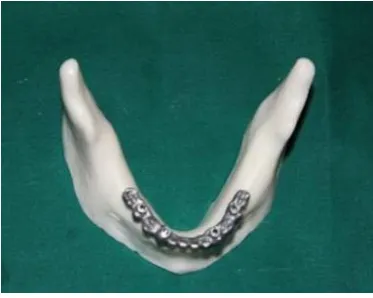
EXPE RI MENT AL MODEL -CO MPLE TELY E DE NTULO US
MANDIBLE
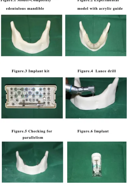
This stud y was conduct ed usi ng a pol yuret hane isot ropi c experim ent al model (compl et el y edent ul ous mandi ble) sim ul ating t he curve of a human m andibl e (Fi g1). P ol yurethanes has hi gh modul us of el asti cit y (347.90 MPa) and these m odels have been developed to simul at e the bone remodeli ng process under m echani cal st imulus in implant s upported prosthesis .1 6
PL ACEME NT O F I MPL ANTS
IMPRESIO N MAKI NG PRO CEDURE
Fol lowing is a descri ption of the imp ressi on m aki ng procedure:
1. Prel iminar y impress ion of experiment al model was m ade with putt y materi al (aquasil - denspl y) usi ng a s tock t ra y(Fi g13). Indi vidual speci al t ra y was m ade wit h acr yli c resin on t he result ant cast (Fi g14) with wax spacer (Fi g15), l eaving an opening in the areas of t he implants .1 8 , 1 9 (open tra y) (Fi g16)
2. Open t ra y im pres si on copi ngs were pl aced ont o the i mpl ants . Access openings of the impression copings were closed wit h provisional restorati ve mat eri al (IR M).
3. Evaluation the custom a cr yl i c im pressi on t ra y in the experim ent al model to make sure that it is wel l adapted and t hat all the im pres sion copings project through t he openings and are not i n cont act with t he acr yl i c resin tra y. (Fi g17)
4. Im pression tra y is removed from the m odel and wax spacer is rem oved from insi de the t ra y.
5. Tra y adhesive was appli ed.
6. Final impression was made wit h m edium bod y (Aquva sil/ M ono phase) impression m at eri al simultaneous l y us ing fi nger press ure . (Fi g18, 21) The impressi on m at eri al was allowed t o s et.
8. The s crew of the Impressi on copi ng, were uns crewed and the impress ion was removed aft er pol ym eriz ation of the acr yli c resin, ens uri ng that the impressi on copi ngs are hel d ri gi dl y by the tra y. (Fi g21)
9. Then disi nfection of the impressi on was done and anal ogs were screwed i nto the im pression copings.
MAKING O F MAS TER CASTING:
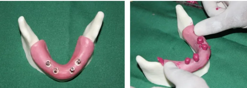
1. Then m ast er cast is made using di e stone (pearl stone t ype IV) along with a soft tis sue m ask (Gi m as k - colt ene) t o sim ul ate soft tissues. (Fi g22)
2. Once the m as ter cast is read y the C ast ab l e abutm ents (UC LA plas tic abutm ent non engaging - Impl ant genesi s) sized 3.7mm were pl aced in t he i mplant anal og present in the mast er cast and screwed.(Fi g23)
WAX PATTERN FOR MASTE R FRAME WORK
Once C ast abl e abut ment s were screwed into m ast er cast im plant analog, wax pat tern i s created using inl a y wax .2 0 (BEGO) (Fi g24)
CASTING O F IMPLANT SUPE RST RUCTURE
The casti ng procedure basi call y use l ost wax technique. The basi c st eps invol ved in the casti ng are
1. Wax patt ern preparat ion. 2. Sprui ng.
5. Casti ng.
6. Recover y of casti ng, cl eaning. 7. Finishi ng and polishi ng.
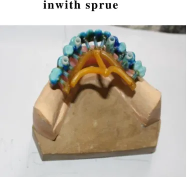
Wax patt ern along with four Castabl e sleeves were att ached to prim ar y sprue form er wax (di rect spruing) of size of 2.5m m (10 gauge). This was connect to the s econdar y sprue of thi ckness 3.4mm (8 gauge). The sprue should be at tached t o patt ern such that it m akes 450 to decreas es the turbul ence of molt en all o y. (Fi g25)
Small auxili ar y sprues are appli ed t o areas of t hin wax patt ern to improve the qualit y of cast ing. 18 -gauges sprues was us ed for this purpos e. The y help in escape of gases duri ng cast ing and ens ure beginni ng of soli di fi cation in criti cal areas b y acting as a heat sink.
Before i nvesti ng, the wax patt ern is cl eaned with a s ynt heti c det ergent to rem ove an y debris, greas e/oil s. An y exces s liquid is shaken off and th e patt ern is l eft to ai r dr y. The thi n film of cl eans er i s left on pattern reduces the surface t ension of wax and permits bett er wet ting of i nvest ment . Som e of the comm ercial l y avail abl e debubblizing agents can be us ed to reduce the s urface tens ion. This decreas es trapping of air on surface of pattern.
Invest ment m at erial (Phosphate bonded – Met aves t delt a) is mixed wit h the li quid provided as per manufact ures i nstruction (powder/liquid ratio 100 g to 22 ml ) and spat ul ated using a m echani cal vacum mixer u nder vacuum press ure and invest ed wit h the hel p of a vibrat or to reduce voids. Aft er the investment set s the investment is tapped out of ring.
Then burnout i s done. Wax elimi nation or burnout cons ists of heating the investm ent in a therm ost ati call y cont rol led furnace until all traces of the wax are vaporized.
CASTING PRO CE DURE :
Heat source used for t his procedure is i nducti on mel t ing. Induct ion casti ng is used to m elt base met al allo ys of hi gh mel ting temperature. Once the allo y is m elt it is cast using cent rifugal machine.
PRO CEDURE :
1. The force ex ert ed b y the m achine i s provided b y t he i nbuilt motor.
2. Bal ancing t he m achi ne shoul d have been done before the ring is heat ed b y placi ng t he ring, along with t he crucibl e and pell ets, on the casting m achi ne so that the arm is bal anced t o compens at e for the wei ght of t he ring and the i nvestm ent .
3. Preheati ng t he al lo y to its melting point is done b y pl acing the allo y i n the cruci bl e and keeping this al ongsi de the cas ting ring in the burnout furnace.
4. Then the ring i s taken out of the heat ing furnace and pl aced firml y agai nst the back pl ate of t he m achi ne. Then the crucible is moved up against t he sprue hol e end of the ring. The cruci ble also has a hol e in i t. Thus b oth the holes are up against each other.
5. The allo y is heat ed agai n until a red glow appears on the surface with shi n y mi rror li ke surface. This i ndi cat es it s proper fusion. 6. At t his st age arm of the machine i s re l eas ed b y dropping the s top
Aft er t he c ast m et al cools , Divesti ng and C asti ng recover y is done. Before an y fit ting of the framework can begin, the cas ting must be t rimm ed. Aft er t his procedure the fram ework is sand bl ast ed and finis hing is done. (Fi g27,36)
DUPLICATIO N O F FRAME WORK FOR CO NVE NTIO NAL WAX
PATTE RN AND CASTING:
The m ast er framework was dupli cat ed us ing dupli cati ng sili cone and casti ng wax (BEGO). Ten such wax patt erns were m ade. (Group I conventional -Tot al t en sam pl es) (Fi g28.29,30)
DUPLICATI NG TH E MASTER CASTING FO R FAB RI C ATION O F
3D PRI NTE D RESI N PATTE RN AND CASTI NG:
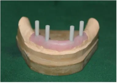
Mast er fram ework was scanned b y opti cal scanner to get a virtual image of mast er cas t and desi gning i n done for screw ret ained frame work. Aft er finis hing, t his CAD dat a (Fig32) i s t rans ferred into a 3D printe r m achine (Fi g31) t o get 3D print ed wax patt erns of fram eworks. Ten such patt erns were made (Group II 3D pri nt ed -t en s am ples ) (Fi g 33,35) and tr y in done i n experim ent al m odel .
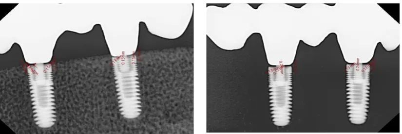
CHECKING O F FIT O F FRAMEWORK USI NG RADIOGRAPH
TECHNIQUE :
A long cone i s used to t ake x -ra ys wi th paral lel ing expos ure techni ques (Fi g37). RVG s ensor is held parallel to the long axis of t he implant usi ng fi lm -holding i nst rum ent s. The cent ral ra y is direct ed t o pas s at a perpendi cular angl e t o both the im plant and the fi lm. Since the s lope and curvat ure of the dent al arches and the alveol ar proce ss es are parallel to thei r long axes, t he film must be held awa y from the implant. This m et hod provides a target -film dis tance of approximatel y 16 inches. Enlargement is mi nimized, however, b y increasing the target-film dist ance to 16 i nches, t hus using th e parall el ra ys . An extension cone is us ed t o increase t he target -film dist ance. And finall y x -ra y is m ade with exposure t ime of 0.18 seconds .
Measuring tools in RVG (VAT TEC H) soft ware (EZDENT - i), was us ed to ass es s t he fit of the fram ework. The dist anc e between the top of the implant at speci fi ed location and t he correspondi ng surface of t he casti ng was measured using a s cal e tool. This li near dist ance gi ves the misfit of the cas ting at that location. The mis fit dist ances
were m easured at four disti nct locations (M esi al, M id -m esi al, Mid-dist al and Dist al) (Fi g42) i n each im plant abutm ent junct ion of all
Figu re.1 Mod el -Completely Figu re.2 E xperi men tal
eden tulou s mandibl e mod el with acryli c guide
Figu re.3 I mpl ant ki t Figu re.4 Lan ce dril l
Figu re.5 Ch eckin g f or Figu re.6 I mpl ant
paral lel is m
[image:58.595.88.508.79.703.2] [image:58.595.93.504.128.262.2]Figu re.7 I mpl ant Figu re.8 Pil ot dri ll
using guid e
Figu re.9 H and tigh tening Figu re.10 Pl acemen ts of
of i mplan t i mp lants in A B D E p osi tion
Figu re. 11 I mplan t with Figu re.12 Making of pri mary
i mpres sion p os t i mpres sion of model
[image:59.595.88.509.28.734.2] [image:59.595.92.509.126.255.2]Figu re.13 Pu tty i mp ression Figu re.14 Pri mary cast
of th e mod el
Figu re.15 Fab ri cati on Figu re.16 Op en tray
of sp ecial tray with spacer
Figu re.17 Open tray in Figu re.18 Making i mpres sion
the model with mediu m b ody
[image:60.595.89.506.64.521.2] [image:60.595.94.507.587.735.2]Figu re.19 Splitting to Figu re.20 Res in to
conn ect th e post s tabil ize th e post
Figu re.21 Making of final Figu re.22 Mas ter cast
i mpres sion with gingi val forme r
Figu re.23 Mas ter cast wi th Figu re.24 Mas ter cast
Cas tabl e sleeve with wax pattern
[image:61.595.90.506.125.260.2] [image:61.595.315.503.585.721.2] [image:61.595.91.283.586.721.2]Figu re. 25 Mas ter cast Figu re. 26 Moun tin g
inwith sp rue cas ting ring
Figu re. 27 Mas ter Frame work Figu re.28 Frame w ork in
duplicating box
Figu re. 29 Duplicati ng sili con e Figu re. 30 Duplicated wax
i mpres sion with patterns
[image:62.595.85.517.34.758.2] [image:62.595.92.280.102.279.2] [image:62.595.307.506.117.281.2] [image:62.595.92.285.379.507.2]Figu re. 31 3D Prin ti ng Figu re.32 CAD data
machine
Figu re.33 3 D Prin ted Fig.34 3D printed pattern in
resin pattern exp eri men tal mod el
Figu re.35 Framework in Figu re. 36 Framew orks
exp eri men tal mod el
[image:63.595.81.516.57.568.2] [image:63.595.96.250.84.284.2] [image:63.595.318.503.138.293.2] [image:63.595.92.279.616.765.2] [image:63.595.312.507.616.762.2]Figu re. 37 Making of x ray Figu re. 38 RVG i mage
with parall eling device
Figu re. 39 RVG i mage wi th Figu re. 40 RVG i mage with
misfit measuremen ts misfit measuremen ts
Figu re. 41 RVG i mage wi th Figu re. 42 RVG i mage wi th
misfit measuremen ts misfit measuremen ts
[image:64.595.89.508.70.523.2] [image:64.595.92.290.128.265.2] [image:64.595.94.507.601.739.2]RESULTS
The meas ured mis fit of t he m et al fram ework and the impl ant for the ten s am pl es i n each group was tabul at ed i n Tabl e 1&2 . The result shows that t he values of Group 1 were m ore varied than t hos e of Group 2 as s een i n Graph 1 .
The m ean of the misfit in each location was cal culat ed and tabulat ed in Tabl e 3,4,5,6. A m ean of means for each t ype of wax patt ern was cal culat ed (Ta bl e 7.) overall mean values at ABDE positi on for Group 1 - (.1250, .1210, .1700, .1340, .1280, .1630, .1300, .1780, .1390, .1350, .1390, .1380, .1460, .1520, .1390, .1420) and Group 2 - (.1530, .1210, .1150, .1320, .1210, .1360, .1310, .1480, .1440, .1360, .1490, .1480, .1240, .1290, .1460, .1390).
STATISTI CAL ANALYSIS :
All data were st atis ticall y anal yz ed wi t h a dedi cated software (SPSS 19).As the di stribution of dat a s et followed a normal curve and the dat a were cont inuous val ues, which came in pai rs , a st udent t -t est was us ed to st atisti call y anal yze the dat a set .
Student t test of the vari ous locations m ade showed st atisti call y si gni fi cant difference bet ween Group 1 & 2 at M esi al A, Mid Mesi al A, Mid Di st al A, Mi d Distal B, Dist al B, Mi d Dist al D, Dist al D, Mesi al E and Mi d Mesi al E. Of the 16 l ocati ons anal yzed, 9 of the locations showed si gni fi cant difference.
TABLE 1 - MIS FIT MEAS URE ME NT O F GROUP I
C o n v e n t i o n a l w a x p a t t e r n I m p l a n t
P o s i t i o n A B D E
M e s i a l M i d d l e M e s i a l
M i d d l e
D i s t a l D i s t a l M e s i a l
M i d d l e m e s i a l
M i d d l e
D i s t a l D i s t a l M e s i
a l
M i d d l e M e s i a l
M i d d l e
D i s t a l D i s t a l m e s i a l
M i d d l e M e s i a l
M i d d l e
D i s t a l D i s t a l
S a m p l e 1 0 . 1 2 0 . 1 5 0 . 1 5 0 . 1 5 0 . 1 3 0 . 1 2 0 . 1 3 0 . 2 1 0 . 1 2 0 . 1 5 0 . 1 3 0 . 1 2 0 . 1 5 0 . 1 5 0 . 1 2 0 . 1 6
S a m p l e 2 0 . 1 3 0 . 1 3 0 . 2 1 0 . 1 2 0 . 1 3 0 . 2 4 0 . 1 3 0 . 1 8 0 . 1 5 0 . 1 2 0 . 1 5 0 . 1 5 0 . 1 5 0 . 1 6 0 . 1 5 0 . 1 1
S a m p l e 3 0 . 1 2 0 . 1 3 0 . 1 6 0 . 1 3 0 . 1 2 0 . 1 8 0 . 1 4 0 . 1 8 0 . 1 4 0 . 1 3 0 . 1 5 0 . 1 5 0 . 1 4 0 . 1 6 0 . 1 4 0 . 1 4
S a m p l e 4 0 . 1 2 0 . 1 4 0 . 1 5 0 . 1 4 0 . 1 3 0 . 1 4 0 . 1 3 0 . 1 7 0 . 1 6 0 . 1 5 0 . 1 3 0 . 1 3 0 . 1 5 0 . 1 5 0 . 1 3 0 . 1 4
S a m p l e 5 0 . 1 3 0 . 1 5 0 . 1 7 0 . 1 3 0 . 1 2 0 . 1 7 0 . 1 2 0 . 1 5 0 . 1 4 0 . 1 4 0 . 1 4 0 . 1 4 0 . 1 4 0 . 1 4 0 . 1 5 0 . 1 2
S a m p l e 6 0 . 1 2 0 . 1 3 0 . 1 9 0 . 1 3 0 . 1 3 0 . 2 1 0 . 1 3 0 . 2 1 0 . 1 3 0 . 1 3 0 . 1 3 0 . 1 3 0 . 1 5 0 . 1 6 0 . 1 5 0 . 1 3
S a m p l e 7 0 . 1 3 0 . 1 4 0 . 1 6 0 . 1 5 0 . 1 4 0 . 1 5 0 . 1 4 0 . 1 9 0 . 1 2 0 . 1 3 0 . 1 4 0 . 1 4 0 . 1 4 0 . 1 5 0 . 1 4 0 . 1 5
S a m p l e 8 0 . 1 3 0 . 1 5 0 . 1 8 0 . 1 2 0 . 1 3 0 . 1 7 0 . 1 3 0 . 1 6 0 . 1 4 0 . 1 2 0 . 1 5 0 . 1 5 0 . 1 5 0 . 1 4 0 . 1 3 0 . 1 6
S a m p l e 9 0 . 1 2 0 . 1 3 0 . 1 7 0 . 1 5 0 . 1 2 0 . 1 3 0 . 1 2 0 . 1 8 0 . 1 4 0 . 1 5 0 . 1 3 0 . 1 3 0 . 1 4 0 . 1 6 0 . 1 4 0 . 1 6
[image:67.842.29.824.117.500.2]TABLE 2 - MIS FIT MEAS URE ME NT O F GROUP II
3 D P r i n t e d p a t t e r n
A B D E
M e s i a l M i d d l e M e s i a l
M i d d l e
D i s t a l D i s t a l M e s i a l
M i d d l e M e s i a l
M i d d l e
D i s t a l D i s t a l M e s i a l
M i d d l e M e s i a l
M i d d l e
D i s t a l D i s t a l M e s i a l
M i d d l e m e s i a l
M i d d l e
D i s t a l D i s t a l
S a m p l e 1 0 . 1 6 0 . 1 1 0 . 1 1 0 . 1 2 0 . 1 3 0 . 1 5 0 . 1 5 0 . 1 6 0 . 1 5 0 . 1 3 0 . 1 5 0 . 1 6 0 . 1 3 0 . 1 5 0 . 1 5 0 . 1 5
S a m p l e 2 0 . 1 5 0 . 1 3 0 . 1 2 0 . 1 5 0 . 1 1 0 . 1 2 0 . 1 1 0 . 1 2 0 . 1 5 0 . 1 5 0 . 1 6 0 . 1 6 0 . 1 1 0 . 1 1 0 . 1 6 0 . 1 2
S a m p l e 3 0 . 1 5 0 . 1 2 0 . 1 1 0 . 1 2 0 . 1 2 0 . 1 3 0 . 1 4 0 . 1 3 0 . 1 3 0 . 1 2 0 . 1 5 0 . 1 5 0 . 1 3 0 . 1 2 0 . 1 6 0 . 1 3
S a m p l e 4 0 . 1 6 0 . 1 1 0 . 1 2 0 . 1 4 0 . 1 1 0 . 1 3 0 . 1 3 0 . 1 4 0 . 1 3 0 . 1 4 0 . 1 4 0 . 1 5 0 . 1 1 0 . 1 4 0 . 1 5 0 . 1 4
S a m p l e 5 0 . 1 5 0 . 1 3 0 . 1 2 0 . 1 5 0 . 1 3 0 . 1 3 0 . 1 3 0 . 1 5 0 . 1 4 0 . 1 3 0 . 1 5 0 . 1 4 0 . 1 2 0 . 1 3 0 . 1 4 0 . 1 5
S a m p l e 6 0 . 1 5 0 . 1 2 0 . 1 2 0 . 1 3 0 . 1 2 0 . 1 4 0 . 1 2 0 . 1 6 0 . 1 5 0 . 1 4 0 . 1 6 0 . 1 4 0 . 1 3 0 . 1 3 0 . 1 3 0 . 1 3
S a m p l e 7 0 . 1 6 0 . 1 1 0 . 1 1 0 . 1 3 0 . 1 3 0 . 1 5 0 . 1 5 0 . 1 5 0 . 1 5 0 . 1 5 0 . 1 4 0 . 1 5 0 . 1 2 0 . 1 2 0 . 1 5 0 . 1 3
S a m p l e 8 0 . 1 5 0 . 1 3 0 . 1 1 0 . 1 2 0 . 1 1 0 . 1 4 0 . 1 5 0 . 1 6 0 . 1 5 0 . 1 2 0 . 1 4 0 . 1 3 0 . 1 4 0 . 1 2 0 . 1 5 0 . 1 4
S a m p l e 9 0 . 1 6 0 . 1 3 0 . 1 2 0 . 1 4 0 . 1 2 0 . 1 4 0 . 1 2 0 . 1 6 0 . 1 4 0 . 1 4 0 . 1 5 0 . 1 6 0 . 1 3 0 . 1 3 0 . 1 4 0 . 1 5
[image:68.842.37.812.128.508.2]TABLE 3 -ST ATIS TICAL ANAL YSIS IS USE D TO EVAL UATE THE FITTI NG O F
SUPE RSTRUCT URE I N POS ITIO N A
Variabl e Groups N Mean Std. Deviation Mean
Differen ce
T Valu e P Value
Mesi al - A Conventi onal patt ern
10 .1250 .00527
-.02800 -10.340 <0.001
3D pri nt ed 10 .1530 .00675 Middl e M es ial A Conventi onal
patt ern
10 .1390 .00876
.01800 4.597 <0.001
3D pri nt ed 10 .1210 .00876 Middl e Dist al A Conventi onal
patt ern
10 .1700 .01886
.05500 8.883 <0.001
3D pri nt ed 10 .1150 .00527 Dist al A Conventi onal
patt ern
10 .1340 .01265
.00200 .359 .724