REALISTIC SIMULATION OF AERODYNAMIC LOADING FOR MODEL TESTING OF FLOATING WIND TURBINES
Alexander H Day, University of Strathclyde Glasgow, Scotland David Clelland, University of Strathclyde Glasgow, Scotland
Elif Oguz, University of Strathclyde Glasgow, Scotland Saishuai Dai, University of Strathclyde Glasgow, Scotland José Azcona Armendáriz, CENER Sarriguren, Navarra, Spain
Faisal Bouchotrouch, CENER Sarriguren, Navarra, Spain Juan Amate Lopez, Iberdrola Ingenieria y Construccion Madrid, Spain
Gustavo Sánchez, Iberdrola Ingenieria y Construccion Madrid, Spain Gonzalo González Almeria, Iberdrola Ingenieria y Construccion Madrid, Spain
The simulation of wind loading for tank testing of floating wind turbines presents a variety of severe challenges. The floating platform naturally responds to wave loadings which are Froude-scaled, whilst the turbine forces respond to aerodynamic loads which are Reynolds-scaled. It is possible to account for Reynolds effects by appropriate distortion of the rotor geometry, nonetheless, construction and operation of a working scale rotor is extremely challenging due to the large size, very light weight, and complex control requirements, while relatively few wave tanks have the ability to generate suitable wind fields.
The current study reviews the approaches used to simulate wind loading on floating wind turbines in wave tanks and describes the deployment of an “software in the loop” (SIL) approach in which the thrust component of the wind load is generated using a high-speed fan located on the model in line with the rotor drivetrain. The six-degree-of-freedom platform motion is measured during the tests, and the aerodynamic thrust related to the instantaneous position and velocity of the platform is calculated in real time using a modified version of the well-known FAST aero-hydro-servo-elastic software code. This calculated thrust is then used to control the fan speed to generate the physical thrust in the model test.
Using this approach it is possible to explore the impact of different wind environment, rotor configurations, and control strategies without the need for a complex model of the rotor, and without generation of wind over the tank. In the present study, the approach is deployed for an innovative shallow water tension-leg platform (TLP) developed by Iberdrola.
1. Introduction: Simulation of Wind Loads on Model Floating Wind Turbines
For floating offshore wind turbines (FOWTs) there is generally significant coupling between the forces generated by the rotor and the response of the system as a whole. This coupling will affect many aspects of the platform dynamics; in particular the turbine aerodynamics will contribute to the motion damping of the system in modes which affect the instantaneous inflow to the turbine. This can affect key parameters such as the accelerations at the nacelle. The mean aerodynamic thrust loads will generate a mean mooring offset which will affect the peak and long-term mooring loads and may in some cases have a significant impact on some modes of motion while the mean torque on the rotor will generate heeling moments on the floater. In addition to the aerodynamic loads, the turbine generates gyroscopic moments on the floater, which may excite unwanted motions – for example a turbine pitching in co-linear wind and waves will generate yawing moments. There may also be some coupling between the blade pitch control system and the platform motions which may result in instabilities of the system.
Model tests without simulation of the rotor forces can be carried out at preliminary stages of the tests or for special purposes, such as comparison of different support structures in terms of their responses to waves, or for the validation of numerical models. This decoupling may also be appropriate where tests aim to examine dynamic responses of the tower and support structure in extreme weather when the turbine will typically be shut down. Hence in these cases, hydrodynamic tests can be carried out without the rotor as long as the rotor mass is represented correctly (e.g. de Ridder et al. (1)). Even then, the wind drag on the tower and parked rotor is neglected.
However tests aiming at evaluating the global response of the system from the concept validation stage to the prototype and demonstration stage should include modelling of the rotor-generated forces due to the coupling present between the platform dynamics and the rotor-generated forces and moments.
2. Approaches for Coupled Aero-Hydrodynamic Tests
2.1Simplified Simulation without Wind Generation.
A number of methods may be employed to simulate the presence of the rotor without representing the rotor aerodynamics directly, although none capture all of the physics of the fully-coupled system. A lightweight line may be attached at the rotor hub and tensioned using a weight to simulate the steady aerodynamic thrust. However the mass properties of the system will inevitably be incorrect, and this approach neglects the aerodynamic damping imparted by the rotor on the system as well as the gyroscopic effects and the steady torque. This approach can only be justified for rough preliminary estimation of the maximum mooring offset (e.g. Chujo, et al. (2)).
correctly, while orientation of gyroscopic moments in relation to steady moments, and the behaviour of the magnitude and direction of the thrust vector as the turbine pitches present some further challenges.
2.2Simplified Simulation with Wind Generation.
If a simulated wind field can be created in a tank, it is possible that a solid or porous disc may be used in place of the rotor. The disc should be sized to generate a drag load in the simulated wind field corresponding to the predicted mean thrust on the turbine. Some challenges may result from the unsteadiness of the flow around the disc when pitching in waves. Gyroscopic effects may be modelled by employing a Froude-scaled rotating disc or a separate rotating arm deployed downwind of the disc (see Cermelli et al. (4)). This approach neglects the aerodynamic torque exerted by the rotor on the platform as well as blade / tower interactions.
2.3Rotor simulation in fully-coupled tests.
Direct modelling of a floating wind turbine is often achieved using a working rotor in a wind field generated by a series of fans. The size of modern wind turbines designed for offshore deployment results in scale ratios typically in the region of 1/50 – 1/100. Examples are given in Chujo et al. (2) for a spar OWT, Shin et al. (5) for a semi-submersible OWT and Goupee et al. (6), for spar, semi-submersible and TLP. Particular challenges in this approach with respect to the wind generation include the generation of a large-volume wind field in a wave tank close to a wavy water surface, particularly in tests with large waves, and especially where tests are intended to include the representation of wind gradients and the wind turbulence. At 1/50 scale, a wind field of the order of 4m in diameter must be generated. The design of a wind system for use over a wave tank is discussed by De Ridder et al. (7).
The construction of the model floater and turbine also presents substantial challenges. Correct modelling of the gyroscopic moments introduced by the rotor requires Froude scaling of the mass properties and rotor speed. However modelling the mass properties of the rotor at small scale requires very lightweight materials of high strength. For example, a 1/50 scale model of the NREL 5MW turbine blade is 1.23m long, but has a mass of only 140g, whilst reduction to 1/80 scale leads to blades of 0.77m length and mass of 35g. It can be difficult to achieve the necessary combination of accurate geometry and very low mass using conventional model-making techniques. Even when the mass requirements are met, further challenges relate to the impact of the blade elasticity in unsteady motions and flow.
The minimum requirement for modelling the presence of rotor in a fully-coupled FOWT test is the correct reproduction of the mean wind thrust load, which drives pitch moments and surge forces and thus mooring offsets and motion damping. If simulation of gyroscopic effects is desired, Froude similarity for the rotor must be maintained via rotor RPM and mass properties. However, application of Froude similarity to the steady wind speed results in substantially incorrect modelling of the rotor aerodynamics. The low Reynolds number conditions can cause substantially dissimilar flows with the relatively thick sections often employed in offshore wind turbines leading to reduced lift, increased drag, and unrealistically low thrust and torque coefficients compared to the full-scale foils. The small model size also results in increasing influence of imperfections in geometric representation on the flow (Muthanna et al., (8)).
the Froude-scaled value to compensate for the low thrust coefficient. The ratio of unsteady velocity (caused by Froude-scaled platform motions) to mean velocity will then be reduced leading to incorrect modelling of unsteady effects, while if rotor speed is maintained at Froude-scaled values, to retain correct gyroscopic moments, then tip-speed ratio will be incorrect, resulting in incorrect torque. Nonetheless, results show that the aerodynamic damping of the platform pitch generated by the turbine is modelled with a reasonable degree of accuracy.
Turbulence stimulators may be placed on the blade leading edge; however this may not on its own improve the turbine performance adequately, and can yield unrealistic results in laminar separation or during flow re-attachment. Finally the rotor may be redesigned, by modifying blade sections to account for Reynolds number effects, or by utilizing unconventional solutions such as changing the number of blades and the rotor diameter. This can involve choice of laminar flow sections for the model scale rotor so that the model rotor design can simulate as closely as possible the correct full-scale mean thrust and torque coefficients at the model-scale Reynolds Number (based on blade chord), whilst still maintaining the correct mass properties. Examples of this technique are given by De Ridder et al. (7), and Martin et al. (10).
Contribution of the wind load to global response of the FOWT is also strongly affected by the pitch control strategy of the turbine. Some examples of successful model tests of FOWTs in wind and waves including direct modelling of the blade pitch control system were reported by Chujo et al. (2) and De Ridder et al. (7). However this remains challenging and expensive.
3. Software-In-The-Loop Simulations of Floating Offshore Wind Turbines
A further possibility is to utilize the idea of “software-in-the-loop” in which an active control system drives an actuator in real time to generate some of the system behavior in a model test. This type of approach requires that the actuated forces acting on the model can be predicted in real time with an acceptable degree of accuracy, and is typically deployed when the forces cannot be generated with sufficient realism by a scale model operating in the same physical manner as the full-scale prototype via aerodynamics, hydrodynamics, structural response, control systems or a combination of these.
Several factors may limit the actuating the forces through direct physical simulation. These may be the lack of ability to simulate part of the physical environment (e.g. lack of wind generation in a test tank), issues of the size of the facility (e.g. simulation of spread moorings), or issues of the similarity between model and full-scale prototype as discussed above.
Zamora-Rodriguez et al., (13) also generated the unsteady aerodynamic thrust force in a hydrodynamic test of a floating wind turbine using a speed-controlled fan.
In the present study the software in the loop approach was used to control a ducted fan to simulate the aerodynamic thrust load on a TLP floating wind turbine in the Kelvin Hydrodynamics Laboratory at the University of Strathclyde. The tank is 76m long, 4.6m wide and can generate waves of over 600mm in height at water depths ranging from 1.6m-2.3m using four wave-absorbing paddles. The tank is fitted with a sloping beach of total length 12m which has a reflection coefficient of less than 5% over the range of frequencies from 0.3Hz to 1.2Hz.
The adoption of this SIL approach to testing offers several key benefits:
the tests could take place without the need for deployment of a wind generation system
there is no requirement to construct a scale-model (or distorted-scale-model) rotor and drive.
the scale of the tests is dictated only by the hydrodynamics of the floater, which in this case allows a test at relatively large scale.
the test procedure can replicate the forces generated by turbulent or steady wind in a variety of directions relative to the wave heading.
the impact of the turbine control system and blade elasticity may be modelled in the tests
correct simulation of the aerodynamic drag load on the tower and parked turbine in extreme conditions is possible
Some special cases, such as emergency stop tests can be simulated with correct full-scale behaviour.
The SIL system deployed in these tests only attempts to simulate the aerodynamic thrust forces. Gyroscopic moments and aerodynamic torque are neglected. In principle the direction of the thrust vector is arguably incorrect when the platform pitches; however for a TLP, the pitch is extremely small, so it is reasonable to neglect this effect. Technical challenges which must be overcome include generating adequate forces in the direction of interest, and obtaining sufficiently rapid response of the actively-controlled system. Furthermore the response of the controlled system is at best only as good as the numerical model used to control it, and thus the model test lacks the completely physical nature of a conventional test.
4. Experimental Set-up
The experimental set-up is illustrated in Figure 1. The floater consists of a TLP designed for 70m water depth with four pontoons in a cross arrangement each fitted with two tendons. The floater is designed to utilize the bench-mark NREL 5MW turbine (ref). Mass properties of the floater were scaled to yield correct values of the mass, CG, and moments of inertia in pitch and yaw; unfortunately it did not prove possible to model the tower stiffness correctly. Springs were utilized in the tendons to yield correct scaled stiffness, and the model was designed so that the tendon tension could be adjusted from above. The tendons are mounted on a frame which allows the floater to be rotated 45 degrees relative to the wave heading.
Figure 1 Experimental setup
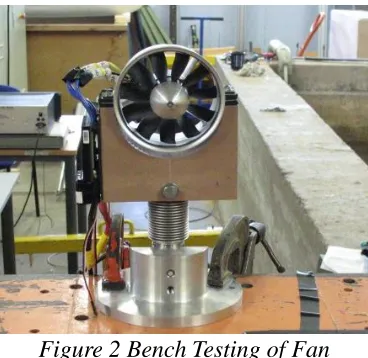
Figure 2 Bench Testing of Fan
A set of dynamic tests then explored the ability of the fan to respond sufficiently quickly to reflect variations in thrust which could be expected from the turbine in turbulent wind, and to test the reliability of the fan over extended periods of running. The dynamic response was found to be acceptable as shown in Figure 3.
[image:6.612.214.398.375.554.2]Figure 3 Time history of target and measured load from fan
The SIL control system for the fan was developed by CENER. The 6DOF rigid-body motions of the platform are computed from the measurements by the Qualisys motion capture system and output in real time to the control PC. The control PC runs a highly modified version of the well-known FAST aero-hydro-servo-elastic code in which the standard hydrodynamic calculations to find instantaneous values for platform position, attitude and velocities are replaced by the values obtained from the tank measurements. The code then calculates the aerodynamic thrust expected with the instantaneous platform location and dynamics in the wind field (either steady or turbulent) and outputs the thrust demand to the fan controller. This in turn controls the fan to rotate at the speed associated with the target value of thrust. The system could also be used in a “dumb” mode without SIL. In this case the fan was simply run at a speed associated with a predefined constant mean thrust.
Inevitably there were a number of practical challenges associated with this system. Extreme care is required to transform between the different co-ordinate systems adopted by Qualisys and FAST. Furthermore it was found that in spite of the use of anti-vibration mountings, the fan excited the tower-top accelerometer so that the measurements from this accelerometer could not be used. However since the TLP exhibits almost no pitch and roll, it was found from tests without the fan that the accelerations at the platform CG and the tower top were almost identical.
5. Sample Results
5.1Test program
The complete test program consisted of a wide range of tests, including free oscillation tests, regular wave tests, irregular wave tests, and a variety of special cases including tendon loss tests, variable water depth tests, and emergency stop tests.
the standard control system as supplied by NREL with their TLP model. The analysis presented here focusses on the results from free oscillation and regular wave tests.
5.2Free Oscillation tests
Free oscillation tests were carried out for all six degrees of freedom of motion. However due to the very high natural frequencies of response, and very rapid motion decay, tests in pitch roll and heave were not reliable. Tests in surge and yaw produced repeatable results. In surge, the tests were executed in three modes: with no wind, with predefined thrust (PT) and with software in the loop (SIL).
Each test was repeated a total of ten times. Several different data analysis procedures were investigated. In the simplest procedure the analytical solution of a linear spring-mass-damper system:
0
mxcxkx (1)
was fitted to the experimental time history in the form:
2
ˆ exp cos 1
x t x x t t (2)
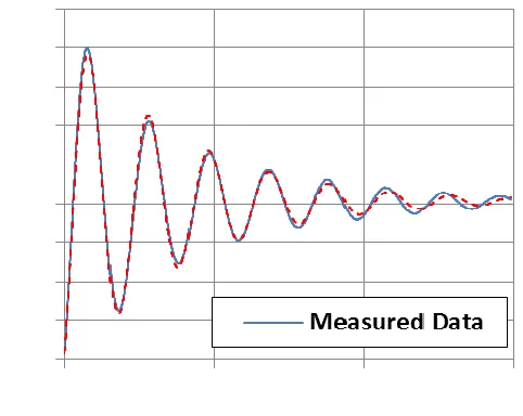
[image:8.612.183.424.428.620.2]where x t is the time history of the displacement, xis the mean value, xˆis the initial amplitude, is the critical damping ratio, is the undamped natural frequency, and is the phase angle. The values of these variables were calculated by minimizing the mean squared error over the time history, using a Generalized Reduced Gradient (GRG) optimization approach.
Figure 4 Typical Linear fit for surge (no wind)
linearized critical damping ratio being 3.5% of the mean value. With predefined thrust, similar results were obtained, with a similar quality of fit and a similar level of repeatability. Based on the linear analysis, the mean period reduced by 0.1%, while the mean critical damping ratio increased by 3.3%. The repeatability was similar, with standard deviations of period and damping ratio of 0.2% and 2.9% of the respective mean values.
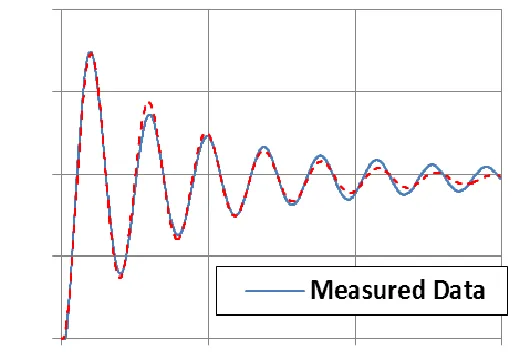
When the SIL was deployed, the results changed somewhat. A typical time history is shown in Figure 5. By comparison with Figure 4, it can be seen that there is a mean offset related to the mean thrust. The level of fit is also less good, with the best-fit linear model over-predicting motion at large amplitudes, and under predicting at smaller amplitudes. This suggests a stronger degree of quadratic damping than in the previous two cases. The mean period is 1.2% lower than the case with no wind, and the mean linearized damping is 17.8% lower. The variation between tests is also increased; the standard deviation of the period is 2.1% of the mean, while the equivalent value for the critical damping ratio is 35.8% of the mean, indicating considerable scatter. This may suggest that the free oscillation test with SIL is more susceptible to variations in initial conditions than the other tests, and possibly an improved test procedure should be developed.
An alternative approach was then deployed in which the fitted time history was generated from the solution of the non-linear equation of motion:
1 2 0
mxc xc x x kx (3)
This was solved using a standard fourth order Runge-Kutta approach, and once again the GRG approach is utilized to generate the best fit values of the mass m, the linear and quadratic damping
1
c and c2 and the restoring k.
[image:9.612.176.432.514.690.2]For the case with no wind, almost no difference was observed in the fit quality, the estimated system mass was identical to five significant figures, while the linear component of damping reduced by 16%. The repeatability was slightly less good; the standard deviation of the mass and linear damping were 0.3% and 1.8% respectively while the standard deviation of the quadratic damping was 5.0%.
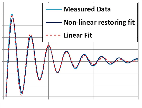
Figure 6 Typical Quadratic fit for surge (SIL)
In contrast for the SIL, the fit was noticeably improved as can be seen in Figure 6. This is to be expected, as the aerodynamic damping can reasonably be assumed to behave more like quadratic than linear damping. In this case the best fit mass was found to be 2.3% lower than in the case of no wind, with a standard deviation of 3.9% of the mean. The mean linear damping was 53% lower than the no-wind case, but with standard deviation of 40% of the mean. In contrast the mean quadratic damping was 77% higher, but with standard deviation 34.3% of the mean.
These results show that the impact of the SIL model on the predicted damping is substantial, and could have substantial impact on the performance of the structure in extreme conditions. However, the variability of the results is high, and further work is required to investigate the causes of this variation. Preliminary investigations show that further improvement in fit to the free oscillation data, particularly towards the end of the motion decay, can be obtained by utilizing a non-linear restoring model, although this has not yet been implemented systematically. An example for the SIL tests using a linear-cubic restoring function along with quadratic damping is shown in Figure 7.
[image:10.612.196.437.523.707.2]5.3Regular wave tests
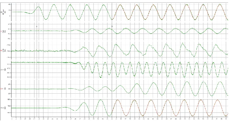
[image:11.612.119.494.182.381.2]A series of regular wave tests were run at in head seas to establish the response amplitude operators of the 6DOF motions. Amplitudes were scaled to 1.0m at full scale. The tests were repeated for conditions of no wind, predefined thrust, and SIL. As with the free oscillation tests, the presence of wind load has two effects – firstly the mean offset, which affects the motions, and secondly the impact on damping. A typical time history of motions with no wind is shown in Figure 8.
Figure 8 Motions with no wind
Some transverse effects are present due to slight asymmetry in model installation. This shows in descending order, the wave elevation, the pitch, yaw, heave, sway and surge motions. The pitch motion has a triangular form with a range of just over 0.1 degrees, while the yaw has a saw-tooth motion with range of around 0.4 degrees. As expected for a TLP the heave motion responds at twice the frequency of the surge, and a small systematic asymmetry between alternate cycles can be seen resulting from slight surge offset.
With the SIL operating the results change somewhat, as shown in Figure 9, for the same wave case as Figure 8. The pitch and yaw motions are similar in magnitude but the time histories exhibit different shapes. There is a pronounced difference in the heave motion, due to the offset. If the surge offset were a little larger, so that the platform never passed the point where the tendons were vertical, then the heave motion would switch to a wave frequency response rather than a double-frequency response.
Figure 9 Motions with SIL
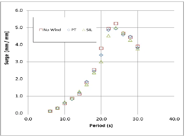
Figure 10 Surge RAO
6. Conclusions
[image:12.612.153.461.325.553.2]development and there are some issues with regard to repeatability and experiment methodology which require further refinement.
Results for free oscillation tests and regular wave responses for the TLP turbine show that the implementation of the SIL approach gives greater quadratic damping, and can affect the RAO in surge by as much as 20% compared to the case with no wind, and more than 10% compared to the case with a predefined thrust.
7. Acknowledgments
The work was funded under the InnovateUK grant “TLPWind UK: Driving down the cost of offshore wind in UK waters”, project reference 101969
The authors acknowledge the support of Iberdrola and CENER to this work.
8. References
1. De Ridder, E., Aalberts, P. van den Berg, J. Buchner, B, Peeringa, J., 2011, The Dynamic Response of an Offshore Wind Turbine with Realistic Flexibility to Breaking Wave Impact, Proceedings, 30th International Conference on Ocean Offshore & Arctic Engineering, OMAE 2011-49563 Rotterdam, The Netherlands
2. Chujo T., Ishida S., Minami Y., Nimura T., and Shunji Inoue S., 2011, Model Experiments on the Motion of a SPAR Type Floating Wind Turbine in Wind and Waves, Proceedings, 30th International Conference on Ocean Offshore & Arctic Engineering, OMAE 2011-49793 Rotterdam, The Netherlands
3. Kraskowski, M., Zawadzki, K., Rylke, A., 2012, A Method for Computational and Experimental Analysis of the Moored Wind Turbine Sea-keeping, Proceedings, 18th Australasian Fluid Mechanics Conference, Launceston, Australia
4. Cermelli, C., Roddier, D. and Aubault, A., 2009, Windfloat: A Floating Foundation for Offshore Wind Turbines Part II: Hydrodynamic Analysis, Proceedings, 28th International Conference on Ocean, Offshore and Arctic Engineering OMAE2009-79231, Honolulu, Hawaii, USA
5. Shin H., Kim B., Dam P.T., and Jung K., 2013, Motion of OC4 5MW Semi-submersible Offshore Wind Turbine in irregular waves, Proceedings, 32nd International Conference on Ocean Offshore & Arctic Eng., OMAE2013-10463 Nantes, France
6. Goupee A.J., Koo B., Kimball R.W., Lambrakos K.F., and Dagher H.J., 2012, Experimental Comparison of Three Floating Wind Turbine Concepts, Proceedings, 31th International Conference on Ocean Offshore & Arctic Eng., OMAE2012-83645 Rio de Janeiro, Brazil
7. De Ridder, E.-J., Otto, W., Zondervan, G.-J., Huijs, F., Saven-ije, F., 2013, State of the Art Model Testing Techniques for Floating Wind Turbines, Proceedings, EWEA Offshore 2013, Frankfurt, Germany
8. Muthanna, C. Visscher, J. H., and Egeberg, T. F., 2013, An Experimental Investigation of Scale Effects on Offshore Wind Turbine Blades, Proc. 32nd Int. Conf. on Ocean, Offshore and Arctic Engineering OMAE2013, Nantes, France
10.Martin, Steven; Day, Sandy; Gilmour, Conor B. 2015 Rotor scaling methodologies for small scale testing of floating wind turbine systems, Proc. 34th Int. Conf. on Ocean, Offshore and Arctic Engineering OMAE 2015
11.Bayati, I., Belloli, M., Ferrari, D., Fossati, F. & Giberti, H., 2014, ‘Design of a 6-DoF Robotic Platform for Wind Tunnel Tests of Floating Wind Turbines‘ Energy Procedia, Vol 53, 2014, Pages 313–323
12.Tsukada, Y., Ueno, M., Miyazaki, H. & Takimoto, T. 2014, An Auxiliary Thruster for Free-Running Model Ship Test Proc. 32nd Int. Conf. on Ocean, Offshore and Arctic Engineering OMAE2013, Nantes, France