Contents lists available atScienceDirect
Materials and Design
j o u r n a l h o m e p a g e : w w w . e l s e v i e r . c o m / l o c a t e / m a t d e s
Piezoelectric microphone via a digital light processing
3D printing process
Benjamin Tiller, Andrew Reid
*
, Botong Zhu, José Guerreiro, Roger Domingo-Roca,
Joseph Curt Jackson, J.F.C. Windmill
University of Strathclyde, Centre for Ultrasonic Engineering, Glasgow G1 1RD, UK
H I G H L I G H T S
• Demonstration of fully 3D printed working piezoelectric microphone.
• Characterization of resin properties and print results for Barium Ti- tanate nanoparticles and Multi-Walled Car-bon Nanotube in a polymer matrix.
• Adaptation of commercial digital light processing 3D printer to multi- mate-rial integrated build.
G R A P H I C A L A B S T R A C T
A R T I C L E I N F O
Article history:
Received 9 November 2018
Received in revised form 4 January 2019 Accepted 5 January 2019
Available online xxxx
Keywords:
Digital light processing Bio-inspired hearing Nanocomposites
A B S T R A C T
In nature sensors possess complex interlocking 3D structures and extremely localized material properties that allow processing of incredibly complex information in a small space. Acoustic sensor design is limited by fabrication processes, often MEMS based, where there is limited scope for fully 3D creations due to planer fabrication methods. Here we investigate the application of 3D printing via digital light processing (DLP) to integrate piezoelectric, conductive and structural polymer layers to create a complete electro-mechanical device. We demonstrate a working piezoelectric acoustic sensor, capable of sending electric signals that can be picked up by pre-amp circuitry fabricated using a commercially available 3D printer. We show that the 3D printing of mechanically sensitive membranes with thicknesses down to 35lm and tunable resonant frequencies is possible and further show it is possible to create a fully working electro-acoustic device by embedding 3D printed piezoelectric and conductive parts. Realizing this design opens up the possibility of generating truly 3D structured functional prints that may be used in bio-inspired design.
© 2019 Published by Elsevier Ltd.
1. Introduction
Additive manufacturing technologies are known to offer bene-fits in terms of the speed, cost and versatility of the platform for small scale production and rapid prototyping, but beyond this the use of additive manufacturing to create materials with complex,
*Corresponding author.
E-mail address:[email protected](A. Reid).
locally tuned physical properties or complex micro-structures not accessible to conventional production techniques is only beginning to be explored [1,2]. Biological sensors represent a paradigm shift in design approach since the sensors are rarely passive recorders of information, but complex micro-controllers in their own right per-forming much of the task of signal processing and filtering before export to the nervous system. In acoustic communication such sig-nal processing often relies on mechanical coupling between strongly anisotropic diaphragms which is difficult to reproduce using tra-ditional micro-machining techniques. Examples such as the helical
shaped cochlear and associated Basilar membrane in mammalian hearing, capable of highly tonotopic mechanical frequency filter-ing [3] or the highly structured acoustic trachea in crickets and grasshoppers [4] have been studied due to their remarkable physical features. These examples are all highly complex 3D structures on a micro/millimeter length scale and pose a challenge to researchers in how to reproduce the essential physical mechanisms that these sys-tems exploit, and yet be possible to fabricate with currently available technology [5,6].
A prime example is the coupled tympanic membranes ofOrmia ochracea, which have extremely accurate directional sensing capa-bilities given the small size and spacing of the ears [7]. InO. ochracea
the tympana are coupled via a raised bridge attached at the centre of each tympanum, where the mechanical properties of the cou-pling bridge must be closely tailored to the resonant frequencies and damping conditions of the system [8]. Many Ormia inspired directional microphones have been developed, with most seeking to flatten the natural 3D structure in a centrally supported see-saw like structure [9,10]. While this fits the requirements of MEMS fabrica-tion very well, since it is often difficult and expensive to fabricate designs requiring much variation in the Z-plane, it introduces com-promises such as requiring an air gap around the periphery of the diaphragms making the devices susceptible to problems of sensitiv-ity and sound path difference around the device. Other examples of biological acoustic sensors such as the tonotopic localization of the Basilar membrane rely on considerably graded thickness varia-tion in which would be extremely difficult to reproduce with MEMS fabrication techniques.
Additive manufacturing holds some promise as a method for cre-ating true 3D biologically inspired sensors. Using fused deposition modelling techniques researchers have printed an acoustically sensi-tive membrane mimicking the geometric shape of a human tympanic membrane [11], and thickness varying membranes for sound absorp-tion [12]. 2D ink-jet and 3D poly-jet printing have been used to build a complete capacitive microphone by printing conductive material onto a thin Mylar film which was then clamped to a 3D printed body [13]. Of particular interest are digital light processing (DLP) based stereo-lithographic printing techniques due to the high achievable print resolutions, 25–50lm in commercially available systems, with custom-built printers reported that lower this still further to 10lm [14], speed of fabrication [15] and compatibility with multi-material printing techniques [16].
Multi-material printing requires the printable resin to be switched during the build, and has been shown for different coloured resins using a top-down stereo-lithographic process with a solvent clean-ing step between each material swap [17] and for hydrogels using digital light processing with an air drying stage between each mate-rial swap [18]. Base polymer resins for 3D printing may be enhanced or given entirely new properties via the addition of nanofillers to the resin, for example by adding barium titanate (BaTiO3) nanopowder into a 3D-printable fluid piezoelectric parts may be created [19-22, or the dielectric properties of the resin may be enhanced [23-25]. Incorporating carbon nanotubes, silvers salts or silica nanoparticles may produce conductive parts [26-29]. Combining such functionally enhanced resins with recent DLP based multi-material printing tech-niques has allowed fully 3D printed micro-electromechanical devices such as capacitive microphones designed using multi-walled carbon nanotube-polymer composites as conductive layers [30].
In this work we demonstrate a piezoelectric microphone, com-prising conductive, piezoelectric and inert polymer based parts, in a single integrated build. Functional 3D-printable composite resins are created by mixing barium titanate nanopowder and multi-walled carbon nanotubes into a PEGDA base monomer resin to make the piezoelectric and conductive parts. The 3D-printed microphone is integrated into a custom build pre-amplifier printed circuit board and the response characterized.
2. Materials and methods
All devices and test samples were created using a commercially available 3D printer (Asiga Pico plus 27), with slicing of CAD mod-els performed by the manufacturer’s software (Asiga Composer). The resolution is advertised as 27lm in the X-Y plane with a minimum build layer thickness of 1lm.
Resins for DLP 3D printing must comprise a base monomer mate-rial together with a photoinitiator. An absorber can be included to control the penetration depth of the light in the material. The monomer used here was poly(ethylene glycol) diacrylate (PEGDA, MW 250), with phenylbis(2,4,6-trimethylbenzoyl) phosphine oxide (Irgacure 819) as the photoinitiator. Sudan 1 (S1) was used as an absorber in concentrations of 0.1%, 0.2%, 0.4% and 0.8% by weight/weight, together with 1% (w/w) Irgacure 819. Preparations are sonicated for 30 min before use and stored in foiled wrapped containers to protect the resins from light.
For the piezoelectric parts barium titanate nanopowder (BaTiO3) with an average particle diameter of 500 nm in concentrations rang-ing from 33% to 66% (w/w) was added to the base resin. The barium titanate resin composite was then mixed in a Thinky ARE 250 plan-etary mixer (INTERTRONICS) before the sonication step. For the conductive parts multi-walled carbon nanotubes (MWCNT) with an average diameter of 9.5 nm and length 1.5 mm were added in con-centrations from 0.1% to 1.25% (w/w). The conductive composite was mixed for 24 h in a magnetic stirrer before use.
PEGDA, Irgacure 819 and Sudan 1 were purchased from Sigma Aldrich. Barium titanate nanoparticles were purchased from US-NANO. Multi-walled carbon nanotubes were purchased from Nanocyl. All materials were used as received.
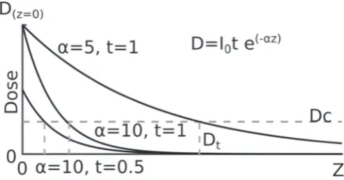
Successful DLP manufacture requires that the exposure time for each layer be tailored to the material’s absorption and intensity of the light source [31]. If we consider the photopolymerizable resin with a surface atz = 0 and an optical irradiance at the surface of the material ofI0in W/cm2then the irradiance at depth z is given by Beer’s law.
I(z) =I0e−az (1)
The parameterais the absorption coefficient of the material in m−1. The corresponding dose at that depth is thenD(z,t) = tI(z), wheretis the time in seconds. At some critical dose the polymer-ization of the resin will have progressed sufficiently for the material to be considered solid.Fig. 1illustrates how the absorption proper-ties of the fluid and the exposure time influence the total UV dose at increasing depth. The minimum dose required to cure the fluid at depthzis shown as a horizontal grey line, with the resulting print thickness (Dt) being the point at which the dose energy drops below this critical dose. The depth of cured material can then be expressed in terms of the dose energy.
Dt= 1
a(lnD0−lnDc) (2)
Fig. 1. Illustration of variation in dose energy with depth (z) for absorption coef-ficients ofa = 10lm−1,t = 0.5 s,a = 10lm−1,t = 1 s anda = 5lm−1, t= 1 s.
In addition to the depth calibration tests of the X-Y resolution of the printer were made using square arrays of blocks with dimensions ranging from 200lm to 1000lm. This additional test was deemed necessary as the diameter of the barium titanate nanoparticles was expected to significantly scatter the 3D printers 412 nm UV LED light source. The results of the print resolution tests may be found inFig. 3. Material changes during the print process were performed by manually pausing the Asiga pico plus at the correct layer height. Sliced CAD files were generated with gaps one or two build layers thick to facilitate this process. The parts were then cleaned in iso-propyl alcohol for 30 s and immediately dried while the printable resin was changed and the printer restarted.
Acouso-mechanical behaviour of 3D printed diaphragms was measured with a scanning laser Doppler vibrometer (Polytec PSV MSA-100-3D). The acoustic source was an ESS Heil Air-Motion Transformer placed 50 cm from the device under test, with signals generated by an Agilent 3325A. A Bruel and Kjaer 4138 1/8 inch microphone was placed within 1 cm of the diaphragm to provide the reference signal. Electrical signals were recorded with the 3D printed diaphragm glued to a PCB circuit board with a custom built pre-amplifier circuit. Signals from the circuit were recorded with a Tektronix DPO 2014 oscilloscope with a sampling frequency of 31.25 MHz and averaged (N = 16).
[image:3.595.310.565.76.145.2]Thickness and morphology measurements were taken with a dig-ital micrometer and confirmed via X-Ray Computer Tomography
Fig. 2. Measured membrane thickness for resin and resin composites with increasing exposure time.
Table 1
Estimated attenuation coefficients and critical dose from cured height values inFig. 2.
Resin Attenuation (lm−1) Critical dose (mJ/cm2)
0.2% Sudan 1 0.00839 18.80
0.4% Sudan 1 0.0247 39.70
0.8% Sudan 1 0.0462 156.40
33% BaTiO3 0.0863 2.92
66% BaTiO3 0.136 1.13
1% CNT 0.0530 32.40
using the Bruker Skyscan 1172 with SHT 11 Megapixel camera and Hamamatsu 80 kV (100lA) source.
Testing of d33 of the barium titanate/PEGDA composite were made by laser Doppler vibrometer measurements of the thickness mode resonant frequency [32,33]. Test samples were polymerized between two glass slides with a spacer separation of 150lm and cured in a UV oven for 10 min. Samples were poled for 2 h in silicone oil at 100◦at 10 MV/m before removal and cleaning. The resistivity measurements of PEGDA-MWCNT composites were taken with an ohmmeter on similarly prepared samples with silver paint to reduce the contact resistance between the ohmmeter and the sample.
Models of the 3D-printed diaphragm were created using COM-SOL Multiphysics 5.3a. Simulations primarily used the solid-acoustic interaction interface, where the diaphragms and 3D-printed block were simulated from CAD designs. Resonance frequencies and damp-ing were simulated usdamp-ing the thermo-viscous acoustics physics and eigenfrequency analysis in two phases: the first using a plain PEGDA model where the mechanical properties of the material are estimated as a density of 1183 kg/m3, Young’s modulus of 52.9 MPa and Pois-son’s ratio of 0.32. These models could be compared to impedance analogy and 3D-printed PEGDA only diaphragms and informed the generation of complete electro-mechanical models. The model was reduced to a 1/12 slice of the diaphragm relying on its axial symme-try to reduce computation time.
Simulating the electro-mechanical behaviour of the diaphragm requires knowledge of the mechanical properties of the piezoelec-tric nanocomposite, which was taken as having a Young’s modulus of approximately 1 GPa from nano-indentation tests and a density of 1832 kg/m3. The mechanical properties of the conductive layers were not simulated, but simply treated as boundary terminals. Estimates of the piezoelectric behaviour of the barium titanate composite were made using the strain-charge form with a symmetrical compliance matrix based on the Young’s modulus of 1 GPa above, and a coupling matrix,d, shown as follows:
d=
⎡ ⎢ ⎢ ⎢ ⎢ ⎢ ⎢ ⎢ ⎣
0 0 1×10⁻¹²
0 0 1×10⁻¹²
0 0 3×10⁻¹²
0 1×10⁻¹² 0
1×10⁻¹² 0 0
0 0 0
⎤ ⎥ ⎥ ⎥ ⎥ ⎥ ⎥ ⎥ ⎦
C/m (3)
Estimates of the stress on the membrane was made from impedance analogy, representing the compliances of the diaphragm and cavity as capacitances, damping as resistances and the mass of the diaphragm as an inductance [34]. The lumped diaphragm com-pliance (Cd) is evaluated with reference to the deflection (w) and potential energy of the system (Ep).
Cd=
w2 2Ep
= 9r 2(1−l2)
16pEt3 (4)
[image:3.595.43.291.521.716.2]Fig. 3.The process steps for changing materials mid-print. By pausing the print just before the diaphragm layer is printed the printer ink can be exchanged.
Cbc=
Vbc
q0c20A2v
(5)
where Vbc is the volume of the back cavity, q0 is the density of air,c0 is the velocity of sound in air andAv is the effective area of the diaphragm (here taken from an effective diameter of 2/3 the measured diaphragm diameter). The resonance frequencies of the mechanical system can then be calculated as a simple resonance equation withMas the mass of the diaphragm.
f0= 1 2p(Cd||Cbc)M
(6)
3. Results and discussion
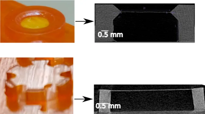
The process used to make the 3D printed microphones is illus-trated inFig. 3. As the diaphragm is not being printed directly onto a previously printed layer, diaphragm thickness must necessarily be greater than 1 build layer thickness since the minimum dose energy for the membrane layer must be sufficient to bond the membrane layer to the previous layer. All results shown here are for a diaphragm thickness of 35lm (Fig. 4) which was found to be a repeatable
and reliable construction when printing with the barium titanate composite.
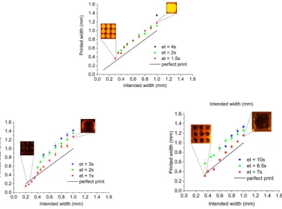
The effect of barium titanate and MWCNT nanofillers on the print accuracy are shown inFig. 5for the base PEGDA resin, barium titanate-PEGDA composite and MWCNT-PEGDA composite. The bar-ium titanate-PEGDA composite’s minimum resolution was 0.35 mm in the X-Y plane, compared to 0.2 mm for the PEGDA resin. Higher concentrations of barium titanate (50% and 66% w/w) were unable to resolve a square array of 1 mm edge/1 mm separation, the largest array tested.
Results for measurements of thed33of the barium titanate PEGDA composite and for the resistivity of the MWCNT-PEDGA composite are given inFig. 6. While higher concentrations of barium titanate nanoparticles are clearly desirable the results of the print resolutions tests inFig. 3indicate that for feature sizes at the millimeter scale prints are limited to composites with less than 50% barium titanate by weight. For the piezoelectric diaphragm printed here the X-Y res-olution was not important and so the higher concentration of 66% by weight was used, resulting in a predictedd33of 3–4 pC/N.
Conductivity tests with the MWCNT-PEGDA composite indicated little benefit from increasing concentration beyond 0.5% by weight. Samples printed on the Asiga pico plus 27 and samples created by polymerizing between two glass sides showed no noticeable differ-ences in resistivity. Resistivity was also found to be invariant with the geometry of the 3D printed part.
[image:4.595.110.471.516.716.2]Fig. 5. X-Y print resolution for a square array of blocks with side lengths and separation of 0.2–1 mm. Results show printed width and intended width for a resin comprised of (top) 0.1% Sudan 1, 1% Irgacure 819 and PEGDA monomer for exposure times (et) of 1, 2 and 3 s (left) of 33% barium titanate, 0.1% Sudan 1, 1% Irgacure 819 and PEGDA monomer for exposure times (et) of 1.5, 2 and 4 s and (right) 1% multi-walled carbon nanotubes, 0.1% Sudan 1, 1% Irgacure 819 and PEGDA monomer for exposure times of 7, 8.5 and 10 s.
Fig. 6.Graphs ofd33(left) and resistivity (right) with increasing weight of barium titanate nanofillers and MWCNTs respectively.
Table 2
Calculated resonance frequencies for lumped parameter model compared with exper-imental results. Models used are for diaphragm compliance only, diaphragm compli-ance in parallel with adiabatic complicompli-ance of cavity and both diaphragm and adiabatic compliance with an additional radial stress of 1.6 MPa.
Model Diaphragm diameter (mm)
1 1.5 2 3 3.5
Experiment 20.43 kHz 12.36 kHz 8.06 kHz 5.73 kHz 3.20 kHz Diaphragm 15.48 kHz 6.88 kHz 3.87 kHz 1.72 kHz 1.26 kHz +Back cavity 15.61 kHz 7.32 kHz 4.81 kHz 3.75 kHz 3.77 kHz +Initial stress 19.55 kHz 11.05 kHz 7.87 kHz 5.67 kHz 4.42 kHz
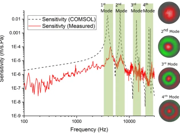
[image:5.595.41.294.677.745.2]Fig. 7. Frequency response function for 3.5 mm PEGDA-barium titanate composite diaphragm and comparison with COMSOL simulation. The first 4 axisymmetric resonance modes are highlighted in green with a good fit found between simulation and measurement. (For interpretation of the references to colour in this figure legend, the reader is referred to the web version of this article.)
to experimental results. For PEGDA-barium titanate composites the diaphragm compliance was much lower and calculations based purely on this gave a reasonable agreement with experimental results (Fig. 7).
The final integration of these components into a single build comprised the PEGDA resin base support structure and two con-ductive layers on either side of a PEGDA-barium titanate composite diaphragm. A 4 mm diaphragm was chosen as having suitable reso-nance characteristics for an acoustic microphone while maximizing the mechanical sensitivity of the device. Electrode placement for the conductive layers was restricted to the outer 200lm of the diaphragm, where the expected strain would be concentrated. The full design and 3D printing work flow are shown inFig. 3. The (0,0)
Fig. 8. Electrical output of the complete device and pre-amplifier to a tone-burst sig-nal at 30 kHz (80 dB SPL, ref 20lPa), with the electro-magnetic interference from the speaker coincident with the tone-burst signal and the measured electrical response being seen after a propagation delay of 0.78 ms.
mode resonance for this diaphragm was recorded at 22 kHz, with a maximum electrical output in response to a stimulating sound field of 80 dB SPL (ref 20lPa) at 1 kHz of−87 dB (V/Pa) with a sig-nal to noise ratio, before averaging, of less than 0 dB. A trace of the microphone and pre-amplifier output is given inFig. 8, showing the electrical output of the device first in response to the electromagnetic bang of the speakers followed by the true signal after an acoustic delay.
4. Conclusions
This work demonstrates the creation via a digital light processing method of additive manufacturing of a complete, working piezo-electric microphone using a commercially available 3D printer. The process adopted here works within the limitations of a commercially available printer, necessitating manual changeovers of the printing vats in order to integrate multiple materials into a single build. A great scope for improving the manufacturing ease and timescales of the process exists if a more bespoke system is adopted, as demon-strated by Kowsari et al. [16]. for example, making material changes within a single layer practical however a far more fundamental limi-tation on the system has been the properties of the piezo-composite material. Measured values ofd33in the range of 2–3 pC/N place the composite’s piezoelectric response in a similar range to that of sput-tered aluminium nitride layers, and considerably poorer than that of PVDF at 20–30 pC/N, with a resulting poor signal to noise ratio. Higher piezoelectric coupling factors have been shown using smaller, or higher aspect ratio barium titanate nanoparticles [36,19] or the addition of surfactants or MWCNTs to the polymer matrix [37].
[image:6.595.36.278.509.700.2]at the base of the layer must necessarily be at the onset of solidifi-cation. The cross-link density in this region is therefore significantly changed from that of the bulk material, which for thin layers can have a noticeable impact on the stiffness and stress of the membrane. Both the issues of stress and enhancement of the piezo-composite are worthy of further work, with predictive models of polymeriza-tion threshold and light intensity such as those described by Gong et al. [14] having potential to be adapted for estimating tension in the diaphragm and improved patterning of piezoelectric composites to create a predictive model for fully integrated 3D printed functional and passive layers.
Data availability
The raw data required to reproduce these findings are avail-able to download from doi.org/10.15129/f7d88ee2-14a9-42be-b3a8-54e7086f6e5e. The processed data required to reproduce these findings are available to download from doi.org/10.15129/f7d88ee2-14a9-42be-b3a8-54e7086f6e5e.
CRediT authorship contribution statement
Benjamin Tiller:Methodology, Investigation, Writing - original draft. Andrew Reid: Formal analysis, Investigation, Conceptual-ization, Writing - original draft, Writing - review & editing.
Botong Zhu:Investigation, Methodology.José Guerreiro: Investiga-tion, Methodology.Roger Domingo-Roca:Investigation, Resources.
Joseph Curt Jackson: Supervision, Writing - review & editing.
J.F.C. Windmill: Supervision, Funding acquisition, Conceptualiza-tion, Writing - review & editing.
Acknowledgments
This research was funded by the European Research Council under the European Union’s Seventh Framework Programme (FP/2007–2013)/ERC Grant Agreement no. 615030, and received funding from the European Research Council under the European Union’s Horizon 2020 research and innovation programme (grant agreement no. 812938), and the Engineering and Physical Sciences Research Council (EPSRC) under grant EP/L022125/1.
References
[1] A.R. Studart, Additive manufacturing of biologically-inspired materials, Chem. Soc. Rev. 45 (2016) 359–376.
[2] J. Gardan, Additive manufacturing technologies: state of the art and trends, Int. J. Prod. Res. 54 (2016) 3118–3132.
[3] H. Reimann, Signal processing in the cochlea: the structure equations, J. Math. Neurosci. (2011).
[4] A. Michelsen, A.V. Popov, B. Lewis, Physics of directional hearing in the cricket Gryllus bimaculatus, J. Comp. Physiol. A. (1994).
[5] J. Hyun, J.H. Kwak, D. Juhyung, S. Kwang, H. Seung, J. Hwan, S. Hur, K. Jae, Basilar membrane-inspired self-powered acoustic sensor enabled by highly sensitive multi tunable frequency band, Nano Energy 53 (2018) 198–205.
[6] R. Domingo-Roca, J.C. Jackson, J.F. Windmill, Bioinspired 3D-printed piezo-electric device for acoustic frequency separation, Proceedings of IEEE Sensors 2017-Decem, 2017, pp. 1–3.
[7] A.C. Mason, M.L. Oshinsky, R.R. Hoy, Hyperacute directional hearing in a microscale auditory system, Nature (2001).
[8] H. Liu, L. Currano, D. Gee, T. Helms, M. Yu, Understanding and mimicking the dual optimality of the fly ear, Sci. Rep. 3 (2013) 2489.
[9] R. Miles, Comparisons of the performance of commercially-available hearing aid microphones to that of the Binghamton Ormia-inspired gradient micro-phone, J. Acoust. Soc. Am. (2017).
[10] J. Zhang, P. Xiao, 3D printing of photopolymers, Polym. Chem. 9 (2018) 1530–1540.
[11] J.-y. Yoon, G.-w. Kim, Harnessing the bilinear nonlinearity of a 3D printed biomimetic diaphragm for acoustic sensor applications, Mech. Syst. Signal Process. 116 (2019) 710–724.
[12] A. Leblanc, A. Lavie, Three-dimensional-printed membrane-type acoustic metamaterial for low frequency sound attenuation, J. Acoust. Soc. Am. 141 (2017) EL538–EL542.
[13] R.I. Haque, E. Ogam, C. Loussert, P. Benaben, X. Boddaert, Fabrication of capacitive acoustic resonators combining 3D printing and 2D inkjet printing techniques, Sensors (Switzerland) 15 (2015) 26018–26038.
[14] H. Gong, B.P. Bickham, A.T. Woolley, G.P. Nordin, Custom 3D printer and resin for 18lm×20lm microfluidic flow channels, Lab Chip 17 (2017) 2899–2909. [15] J.R. Tumbleston, D. Shirvanyants, N. Ermoshkin, R. Janusziewicz, A.R.
John-son, D. Kelly, K. Chen, R. Pinschmidt, J.P. Rolland, A. Ermoshkin, E.T. Samulski, J.M. Desimone, Continuous liquid interface of 3D objects, Science 347 (2015) 1349–1352.
[16] K. Kowsari, S. Akbari, D. Wang, N.X. Fang, Q. Ge, High-efficiency high-resolution multimaterial fabrication for digital light processing-based three-dimensional printing, 3D Printing and Additive Manufacturing, 5, 2018, pp. 185–193. [17] R.B. Wicker, E.W. MacDonald, Multi-material, multi-technology
stereolithogra-phy, Virtual Phys. Prototyp. 7 (2012) 181–194.
[18] A.K. Miri, D. Nieto, L. Iglesias, H. Goodarzi Hosseinabadi, S. Maharjan, G.U. Ruiz-Esparza, P. Khoshakhlagh, A. Manbachi, M.R. Dokmeci, S. Chen, S.R. Shin, Y.S. Zhang, A. Khademhosseini, Microfluidics-enabled multimaterial maskless stereolithographic bioprinting, Adv. Mater. 30 (2018) 1–9.
[19] K. Kim, W. Zhu, X. Qu, C. Aaronson, W.R. McCall, S. Chen, D.J. Sirbuly, 3D optical printing of piezoelectric nanoparticle-polymer composite materials, ACS Nano 8 (2014) 9799–9806.
[20] Z. Chen, X. Song, L. Lei, X. Chen, C. Fei, C.T. Chiu, X. Qian, T. Ma, Y. Yang, K. Shung, Y. Chen, Q. Zhou, 3D printing of piezoelectric element for energy focusing and ultrasonic sensing, Nano Energy 27 (2016) 78–86.
[21] D.I. Woodward, C.P. Purssell, D.R. Billson, D.A. Hutchins, S.J. Leigh, Additively-manufactured piezoelectric devices, Phys. Status Solidi A 212 (2015) 2107–2113.
[22] X. Song, Z. Chen, L. Lei, K. Shung, Q. Zhou, Y. Chen, Piezoelectric component fab-rication using projection-based stereolithography of barium titanate ceramic suspensions, Rapid Prototyp. J. 23 (2017) 44–53.
[23] H. Kim, J. Johnson, L.A. Chavez, C.A.G. Rosales, T.-L.B. Tseng, Y. Lin, Enhanced dielectric properties of three phase dielectric MWCNTs/BaTiO3/PVDF nanocomposites for energy storage using fused deposition modeling 3D print-ing, Ceram. Int. 44 (2018) 9037–9044.
[24] S. Guan, H. Li, S. Zhao, L. Guo, Novel three-component nanocomposites with high dielectric permittivity and low dielectric loss co-filled by carboxyl– functionalized multi-walled nanotube and BaTiO3, Compos. Sci. Technol. 158 (2018) 79–85.
[25] J.Y. Park, Y.Y. Kang, H.W. Yoon, N.K. Park, Y. Jo, S. Jeong, J.C. Won, Y.H. Kim, Viscoelastic properties of a 3D-printable high-dielectric paste with surface– modified BaTiO3, Compos. Sci. Technol. 159 (2018) 225–231.
[26] S.J. Lee, W. Zhu, M. Nowicki, G. Lee, D.N. Heo, J. Kim, Y.Y. Zuo, L.G. Zhang, 3D printing nano conductive multi-walled carbon nanotube scaffolds for nerve regeneration, J. Neural Eng. 15 (2018).
[27] G. Gonzalez, A. Chiappone, I. Roppolo, E. Fantino, V. Bertana, F. Perrucci, L. Scaltrito, F. Pirri, M. Sangermano, Development of 3D printable formulations containing CNT with enhanced electrical properties, Polymer (United Kingdom) 109 (2017) 246–253.
[28] G. Taormina, C. Sciancalpore, M. Messori, F. Bondioli, Advanced resins for stere-olithography: in situ generation of silver nanoparticles, AIP Conf. Proc. 1981 (2018).
[29] J. Odent, T.J. Wallin, W. Pan, K. Kruemplestaedter, R.F. Shepherd, E.P. Gian-nelis, Highly elastic, transparent, and conductive 3D-printed ionic composite hydrogels, Adv. Funct. Mater. 27 (2017) 1–10.
[30] Q. Mu, L. Wang, C.K. Dunn, X. Kuang, F. Duan, Z. Zhang, H.J. Qi, T. Wang, Digital light processing 3D printing of conductive complex structures, Addit. Manuf. 18 (2017) 74–83.
[31] H. Gong, M. Beauchamp, S. Perry, A.T. Woolley, G.P. Nordin, Optical approach to resin formulation for 3D printed microfluidics, RSC Adv. 5 (2015) 106621–106632.
[32] K. Yao, F.E.H. Tay, Measurement of longitudinal piezoelectric coefficient of thin films by a laser-scanning vibrometer, IEEE Trans. Ultrason. Ferroelectr. Freq. Control 50 (2003) 113–116.
[33] J. Hernando, J.L. Sánchez-Rojas, S. González-Castilla, E. Iborra, A. Ababneh, U. Schmid, Simulation and laser vibrometry characterization of piezoelectric AlN thin films, J. Appl. Phys. 104 (2008).
[34] M. Kleiner, Electroacoustics, CRC Press. 2013.
[35] J.Y. Chen, Y.C. Hsu, T. Mukherjee, G.K. Fedder, Modeling and simulation of a con-denser microphone, TRANSDUCERS and EUROSENSORS ’07 - 4th International Conference on Solid-State Sensors, Actuators and Microsystems, 146, 2007, pp. 1299–1302.
[36] W. Choi, K. Choi, G. Yang, J.C. Kim, C. Yu, Improving piezoelectric performance of lead-free polymer composites with high aspect ratio BaTiO3nanowires, Polym. Test. 53 (2016) 143–148.
[37] J. Yan, Y.G. Jeong, Roles of carbon nanotube and BaTiO3 nanofiber in the electrical, dielectric and piezoelectric properties of flexible nanocomposite generators, Compos. Sci. Technol. 144 (2017) 1–10.