Power losses in electrical topologies for a multi-rotor wind turbine system
Full text
Figure
![Fig. 1: Model of a multi-rotor wind turbine system, consisting of 45 rotors [6].](https://thumb-us.123doks.com/thumbv2/123dok_us/1354643.89037/2.595.191.404.368.537/fig-model-multi-rotor-wind-turbine-consisting-rotors.webp)


Related documents
Thus, the increasing pattern of population migration growth affected in west coast urban area like Kuala Lumpur, Penang, Johor and other (Tarmiji et al., 2012). Thus, the urban
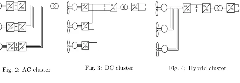
Introduction of power supply circuit, Inductor volt – second balance and Capacitor charge balance, Steady state Analysis for DC – DC converters, Ideal of DC transformer , Losses in
Notably, of the three Rho GTPases, only Rho1 is essential in Aspergillus, and while the ⌬ rho2 mutant shows no remarkable growth abnormality under standard growth conditions, lack
While Regulation 1/2003 – as well as the majority of the NCAs – provided that the fines shall not exceed 10% of the infringer’s total turnover, the Directive now foresees that
Si in root samples supplemented with nanosilica was 72%, 105% and 152% larger as compared to microsilica, sodium silicate and control samples, respectively, which led to
Tumor progression and growth were monitored after 4T1-Luc2 cells inoculation using noninvasive BLI and magnetic resonance imaging (MRI) before and after subsequent injection of
Therefore, further the Pareto-dominated equilibria (12) - (14) are studied depending on the initial ratio of the parties forces and, in particular, the extreme points of the
