Enabling Efficient Engineering Processes and
Automated Analysis for Power Protection Systems
Qiteng Hong,
Member, IEEE,
Steven M. Blair,
Member, IEEE,
Campbell D. Booth,
Victoria M. Catterson,
Senior Member, IEEE,
Adam Dy´sko,
Member, IEEE,
and Tahasin Rahman
Abstract—The reliable operation of power networks depends on the correct configuration of protection systems. These systems involve the coordination of devices across a wide area, each with numerous setting parameters. Presently, protection settings data are typically stored in various vendor-specific proprietary formats, which are difficult to access, interchange, and manip-ulate automatically. Consequently, the engineering processes for implementing modern protection systems are extremely complex, involving multiple software tools from different vendors. This paper presents a novel solution to these challenges, through the use of the data model provided by the IEC 61850 standard, with the System Configuration description Language (SCL) format to represent protection settings data. The design of a Protection Setting data Conversion Tool (PSCT) that can automatically convert existing settings data between proprietary formats and the SCL-based format is presented. A case study of its implemen-tation demonstrates the benefits of the common represenimplemen-tation of protection settings for network operators and other stake-holders. The paper also addresses the challenges that network operators face in migrating to the new approach from existing legacy protection devices and data formats. Adoption of these recommendations and design approaches would shift protection systems from being largely single-vendor solutions to becoming efficient and truly open platforms, capable of supporting future intelligent applications and tools such as automated protection settings validation, diagnostics, and system simulation.
Index Terms—Power system protection, IEC 61850, code gen-eration, substation automation system, system engineering, data translation.
I. INTRODUCTION
P
ROTECTION systems defend power networks againstabnormal operating conditions by isolating faulty
components—typically within milliseconds—to minimize
equipment damage, the risks of wide-area blackouts, and other unsafe or undesirable scenarios. These systems operate in real-time and are safety-critical, but are becoming increasingly challenging to design and validate [1].
The reliable operation of protection systems depends on the correct design and application of numerous configura-tion parameters within a wide range protective Intelligent Electronic Devices (IEDs) in electrical substations. These parameters are known as “protection settings”, and a network operator may need to manage thousands of IEDs, each with
This research is sponsored by National Grid, UK, and supported by John Moyes Lessells Travel Scholarships from the Royal Society of Edinburgh while this work was undertaken.
Qiteng Hong, Steven M. Blair, Campbell D. Booth, Victoria M. Cat-terson and Adam Dy´sko are with the Department of Electronic and Electrical Engineering, University of Strathclyde, Glasgow, UK (e-mail: [email protected]).
Tahasin Rahman is with National Grid, UK.
hundreds of settings. The engineering of protection systems is an extremely complex process, involving the design and specification of numerous, interacting functions, which often require coordination across a wide area.
While standardized data models and formats are increas-ingly being used for power network data representation, storage, and exchange [2], [3], protection settings data are typically stored in vendor-specific formats, such as an arbitrary “binary” representation, Comma-Separated Value (CSV), and plain text. These formats are difficult to access, interchange, and manipulate automatically. For example, [4] has reported the investigation of the blackout event in North America in 2003, where significant efforts have been required to translate the settings data into suitable formats so that associated soft-ware can use the data to conduct automated analysis. Further difficulties, as reported in [1], [4]–[9], include: the need for proprietary tools to access data; the use of different data models, e.g. different representations of physical quantities and naming conventions; and different data formats used to represent the data model. The management of proprietary settings data also presents a significant challenge for protection engineers. These shortcomings are very undesirable for future smart grid developments, which expect that data can be readily accessed, exchanged, and manipulated by multiple intelligent applications automatically.
Furthermore, the existing process for configuring IEDs— an essential step during the overall engineering of protection systems—is based on proprietary protection settings formats. This is inherently complex because both a vendor-independent system-level configuration tool and various vendor-specific IED configuration tools are required, and the configuration in-formation is often stored in separate files, in differing formats [2], [9], [10]. Consequently, true system-level configuration (i.e. to allow the task of designing multi-vendor protection systems to be performed in a single vendor-independent tool) is difficult to implement and is, therefore, largely unavailable to network operators. There is a strong need from users and stakeholders for an efficient solution that allows such vendor-independent “top-down” IED configuration [1], [10]–[15]. The complexity and inefficiency of the present engineering process for protection systems has been well recognised by industry and various international professional working groups, includ-ing IEEE Power System Relayinclud-ing Committee (PSRC) Workinclud-ing Group (WG) H5 and H27, CIGRE WG B5.50, WG B5.31 and WG B5.27 (more details are discussed in Section II-C).
system engineering, in [9] the authors propose the use of the data model provided by the standard IEC 61850 [16] and its standardized System Configuration description Language (SCL) to represent protection settings. In recent years, new IEDs that adopt the SCL format to store protection settings have been implemented [17], which forms an important step towards a vendor-independent solution. However, there are still unresolved issues: 1) the access and manipulation of existing proprietary protection setting data remains difficult for smart grid applications, and 2) for network operators to migrate to the new vendor-independent approach, the transition process would be extremely challenging given the large amount of existing “legacy” data.
The key contribution of this paper is the design and de-velopment of an open framework to address these remaining challenges in the most effective way so as to enable efficient engineering processes and automatic analysis for protection systems. As an illustration of how this open framework can be implemented in practice, a Protection Setting Conversion Tool (PSCT) that allows automatic conversion between proprietary settings data and IEC 61850 standardized SCL-based data is presented. PSCT supports a number of IEDs from different vendors [18]–[21] and protection schemes including distance, overcurrent, and differential. A code generation module has been developed allowing rapid prototyping of extended sup-porting modules for new IED types and other protection functions. The conversion of proprietary settings data to the standardized format using PSCT largely facilitates the intelli-gent applications in manipulating these data. Based on this common representation method, a novel IED configuration process is proposed, which is significantly streamlined and efficient compared with the existing approach. It is shown how PSCT can be used to support the integration of legacy proprietary data to the proposed novel configuration, and how the proposed engineering process can be largely automated with the aid of PSCT. For the avoidance of doubt, the internal algorithms of the IEDs (e.g. for fault detection) are not within the scope of the paper, which instead focuses on using a standardized format to represent the interfaces (i.e. protection settings) between the internal implementation and external applications.
The paper is organized as follows. Section II provides background information relating to the IEC 61850 data model and the SCL format, along with the key benefits of using the SCL format for protection setting data representation. Section III provides a detailed introduction of PSCT. Section IV discusses potential applications and benefits of PSCT. In Section V, a case study is presented that demonstrates the use of the PSCT to convert IEDs' proprietary settings files to SCL-based files for performing system-level multi-vendor protection function analysis.
II. IEC 61850 DATAMODEL FORPROTECTIONSETTINGS
A. Overview of the IEC 61850 data model
IEC 61850 is an international standard for power system au-tomation and communications and a key enabler for smart grid development [16]. A standardized data model and SCL file
format are defined to facilitate interoperability across different vendors' devices. Application functions are decomposed into functional entities entitled “logical nodes” [22], e.g. “PDIS” has been defined in the standard to refer to distance protection. Within each logical node, there are data objects, which are instances of common data classes [23], to describe the function each logical nodes represents. The data objects contain a set of data attributes that formally specify their details, e.g. the numerical value(s), the units, etc.
SCL is a standardized file format based on XML syntax and defined in IEC 61850-6 for information exchange and description of substation functionality [16]. An IED Capability Description (ICD) file, written using SCL, is used to indicate the logical nodes and other parameters supported by an IED. Currently, the use of these standardized data objects for protection settings in protection logical nodes is not mandatory and is not widely adopted. Although there may be concerns about the feasibility of representing protection settings using a common data model given the various proprietary func-tions and features available, the activities of a number of professional organizations' including IEEE PSRC WG H5 and H27 have revealed that the majority of existing protection functions and features can be represented using a standardized data model [7], [24]. The benefits of such an approach are demonstrated in the case study presented in Section V.
In this paper, the distance protection logical node proposed by PSRC WG H5 [7] and the other logical nodes defined in IEC 61850-7-4, along with a number of extensions proposed by the authors, have been adopted for the implementation of PSCT. Should the IEC 61850 standard be updated in the future with new logical node definitions, a solution has been provided by introducing a code generation module that can update the PSCT to adapt to the new standard without a requirement for significant changes. Further details are presented in Section III-C. For protection settings that are not currently defined in the presently-available standardized logical nodes, some information may be lost unless manual interventions are made. However, these settings are generally associated with vendor-specific features which may not be available in other devices. Presently, the majority of the settings can be retained and are sufficient for the applications as presented in Section IV.
B. Key advantages of using SCL as the common format for protection settings data
Presently, protection settings data are typically stored in the following formats: arbitrary binary files, manually-created text files, files exported from binary files into a text- or XML-based format, and databases. The key advantages of using the SCL format to represent protection settings, as opposed to the aforementioned methods, include:
1) The SCL format is fully documented and is openly accessible whereas binary files can only be assessed using vendor-specific software tools.
2) An SCL-based file is formally structured and self-descriptive. Vendor-specific files use arbitrary represen-tations, which varies between vendors.
be encoded in the column title or provided manually in additional written documentation. By contrast, the SCL format is semantically rich, i.e. it inherently and unambiguously defines physical quantities and units, and supports the use of hierarchical data structures. 4) XRIO [25], based on XML syntax, is a commercial
for-mat proposed for protection testing purposes. However, the representation of parameters is proprietary. The proposed SCL format adopts an existing standardized data model, directly providing the schema and syntax for storing logical node parameters.
5) The SCL format is part of the IEC 61850-6 standard and provides a common format for representing a modern substation automation system [16]. Therefore, protection settings data can be stored alongside other system data presented in a SCL file, which facilitates data integration.
6) The SCL format is formally defined by an XML schema [26], which allows the validation of SCL files to be conducted automatically [27]. The generation and manipulation of an SCL file can be automatically per-formed by model-centric software such as the Eclipse Modelling Framework (more details are provided in Section III-B).
Existing IEDs and power system software typically only support vendor-specific protection settings and do not allow importing of SCL-based settings automatically. This presents a significant burden for the development of software that requires the manipulation of protection settings, because each IED type needs to be equipped with a specific data importer. Once the settings are represented in the SCL-based format, only one generic (instead of many vendor-specific) data im-porter would be required, so the effort associated with devel-opment and maintenance of systems that require manipulation of protection settings can be significantly reduced.
C. Related industry activities
There are a number of professional working group activities that are associated with and can be facilitated by the work presented in this paper:
1) The IEEE PSRC WG H5 published a report [7] promot-ing SCL as a common format for IED configuration. A new working group, H27 (Common Format for Relay Settings Data), has also been started [24].
2) CIGRE WG B5.50 [10] is working on a solution for vendor-independent IED configuration, which is discussed in Section IV.
3) CIGRE WG B5.27 published a report [28] on “Im-plications and Benefits of Standardized Protection and Control Schemes” where the standardized format of protection setting files is recommended.
4) CIGRE WG B5.31 proposed potential improvements for the management of protection settings in [29]. The main recommendations include: management of settings should take full advantage of IEC 61850; the engineering process should become more closely integrated with the protection setting process; improved
Code Generation Module
Data Translation Module
Proprietary protection
setting data SCL file
Simplifying IED configuration
process Protection setting
interoperability
[image:3.612.318.556.55.154.2]Intelligent applications PSCT
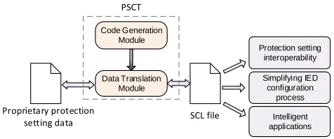
Fig. 1. Overview of the proposed tool and potential applications of the translated SCL-based settings format
software tools are needed to correctly, securely, and efficiently exchange and manipulate protection settings; version management of protection settings is essential; and protection settings should be capable of being accessed by various stakeholder groups.
The research presented in this paper addresses all of the aforementioned working group activities. In particular it demonstrates steps and tools required to meet all WG B5.31 recommendations for future protection setting management.
III. IEC 61850 PROTECTIONSETTINGSCONVERSION
TOOL(PSCT)
This section describes the design of the PSCT, which facil-itates interoperability (and interchangeability) by converting from proprietary formats to SCL. The implementation of this design represents the culmination of research into how to provide protection settings data for intelligent applications for future smart grid developments.
A. Overview
PSCT is implemented using the Java programming language [30]. As illustrated in Fig. 1, PSCT consists of a data trans-lation module and a code generation module. The proprietary protection settings files are converted into SCL files by the data translation module. The code generation module automatically generates code to allow rapid prototyping and support for new IED types and protection functions. A key advantage of the design of PSCT is that this process requires minimal manual input.
B. Data translation
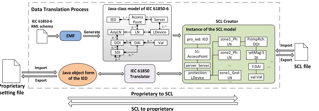
The translation of setting files from proprietary formats to the SCL format is shown in Fig. 2 and involves three main procedures: data importing, mapping, and exporting.
1) Protection settings data importing: This step is required
to access the protection settings data from the original source format for further manipulation and processing.
...
... ...
SCL Creator
pro_ied: IED
S1: AccessPoint
server: Server
protection: LDevice
zone1_Ph: LN
zone2_Ph: LN
zone1_Gnd: LN
...
PsImpRch: DOI
setMag:S DI
val:Val f:DAI ... 0..*
0..* 1..*
1..* 0..1
0..*
0..* 0..*
0..*
IED Access
Point Server
LDevice
0..* SDI
LN
DOI AnyLN
DAI 0..* Val
Java object form of the IED
IEC 61850-6 XML schema
Java class model of IEC 61850-6
IEC 61850 Translator
SCL file
Export Generate
EMF
Instance of the SCL model
Proprietary setting file
Import
Data Translation Process
Import
Export
Proprietary to SCL SCL to proprietary
Fig. 2. Translation process between the proprietary setting format and SCL format
For settings stored in a database, parsing is not necessary because settings can be retrieved directly in software with reference to the database schema. If the settings data resides in a source that cannot be easily parsed, the importer also supports manual data input via a user interface.
The output of the importing step is a Java object represen-tation of the protection functions and the associated settings.
2) Mapping from the proprietary settings to standardized
data objects: The mapping step is performed by the IEC
61850 Translator, shown in Fig. 2, which contains the bi-directional mapping relations between the proprietary settings and the IEC 61850 data objects. Fig. 3 shows an example of mapping from the settings (represented in a proprietary format) within a commercially-available IED [19] to the IEC 61850 data model. PDIS is the logical node defined in IEC 61850 to represent a distance protection zone. One distance
protection zone (e.g. Zone 1ph) is modeled using one PDIS
logical node. The setting parameterR1 Ph. Res(Zone 1 phase
resistive reach) is mapped to the PDIS data object PsRisRch
(positive resistive reach). Some of the IED’s specific features may not be configurable and/or visible to the user, and must be obtained manually. For example, in the original IED there is
no corresponding settable parameter for NgRisRch (negative
resistive reach), because its value is fixed at 25% of the positive resistive reach. The information therefore has to be derived from the vendor's information relating to the IED.
The building of mapping relationships between IEC 61850 data and proprietary parameters is the only manual interven-tion required within PSCT and is only needed once per IED type. All other implementation work is facilitated by a code generation module introduced in Section III-C.
3) Exporting protection settings data as SCL files: IEC
61850-6 provides an XML schema for its data model, which defines the structure, contents, and semantics of a correctly formatted XML document. As illustrated in Fig. 2, the XML schema provided by IEC 61850-6 is used by the open source Eclipse Modelling Framework (EMF) software [31] to auto-matically generate a Java class form of the schema. EMF is
R1 Ph. Res.
× 0.25 × 1
Zone 1 ph Distance
...
... Zone 2 ph
PsR isRch
PDIS1
NgRi sRch
PDIS2 ...
[image:4.612.52.574.59.241.2]Settings in original IED Settings in IEC 61850 data model
Fig. 3. Mapping example: positive and negative resistive reach
built on the Eclipse platform and is designed to facilitate the development of software based on structured models. A similar application of this tool is described in [27].
The exporting step is performed by the SCL Creator, as
shown in Fig. 2. This uses both the class structure generated
by the EMF and the mapping results from the IEC 61850
Translator to create an instance of the model, i.e. it creates
the relevant logical node objects. EMF also supports automatic conversion between valid XML files and Java objects, and this
feature is used by theSCL Creatorto automatically export the
instance of the model (in Java object format) as an SCL file (in XML format).
Validation of the generated SCL files can also be performed by importing each file using EMF, which automatically checks the syntax against the XML schema. The validator introduced in [27] performs further checks such as verifying the use of unique names and valid data types.
SCL model; 2) the reverse mapping process is performed by
theIEC 61850 Translatorto create a Java form of the IED with
the setting values; 3) the Java object can then be exported to any required vendor-specific format. It is important to note that if the SCL-based settings are converted back to the original IEDs’ formats, the conversion can be performed without loss of information. However, when converting the SCL-based files back to proprietary settings for different IEDs with different capabilities, some information may be lost [32]. For example, if there are five instances of PDIS available within the SCL file but the targeted IED only supports four distance protection zones, the information relating to one PDIS zone cannot be implemented by the IED.
C. Code generation
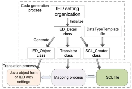
Manual implementation of the translation process would require significant programming time and effort to cater for the large variety of existing IED types and protection func-tions. In particular, the process of creating an instance of the SCL model, which involves building the internal details of logical nodes and assigning values to the relevant data attributes, can be extremely time-consuming if performed manually. Therefore, there is a requirement for an automatic code generation module, to significantly reduce the time and effort required to implement a translator for new IED types and protection functions. This section describes the design and implementation of such a module.
The code generation process, illustrated in Fig. 4, starts with a regrouping of the original IED’s parameters to better match the IEC 61850 modeling approach. This process is referred to as “IED setting organization”. The vendor-specific settings for different IED types may be grouped and managed in different ways and these conventions are often not well aligned to the IEC 61850 data model. For example, the distance zone reach, status, and time delay settings for a given IED [19] are allocated to different groups, while in IEC 61850 all such settings need to be represented in one logical node. The IED setting organization step groups the original setting parameters into “blocks” that provide all the settings required by the corresponding IEC 61850-7-4 logical node, i.e. each block maps to a single logical node instance.
The result of the IED setting organization is used to
initialize the IED Detail Java class, which contains detailed
information about the IED, i.e. the available functions and parameters. As shown in Fig. 4, this information is then used
for generating the IED Object andTranslator classes, which
are used in the data translation process to represent the IED in Java object form and to perform conversion, respectively.
[image:5.612.328.547.54.201.2]As discussed in Section III-B, the mappings between the proprietary data and the IEC 61850 data are IED-dependent, which means that any time the system is extended to incor-porate settings from a new type of IED, there is a one-off requirement to manually develop the mapping relationships for that IED model. This is the only step that requires manual input during the implementation of the translation process, and the mapping development only needs to be performed once for each IED type, as part of the data translation step. The code
Fig. 4. The code generation and data translation process
generation module therefore requires no manual intervention, as it automatically handles the other time-consuming and complex implementation steps. The majority of the coding work is performed automatically to optimize the process for the convenience of protection engineers.
The DataTypeTemplatefile, which is a placeholder for the
DataTypeTemplatesection in the exported SCL file, is an XML
file that contains the standardized definitions of all data types that are required by the SCL file, e.g. the logical node types, data object types, and data attribute types. This file does not need to be manually customized for each IED. The information
provided by theIED Detailobject and theDataTypeTemplate
file is used to generate theSCL Creator class, which creates
an instance of the SCL model.
The key benefits of the code generation process are: it allows rapid development of a data translation process while requiring minimal manual effort; it hides the complexity of building an SCL file from the user because the hierarchical structure of the SCL model is automatically generated; and any future changes to the standardized IEC 61850 data model are reflected in
the DataTypeTemplate file and the XML schema, which are
both automatically utilized by the code generation module. This provides a convenient framework for updating the PSCT system over time without requiring significant effort, which is particularly useful when the existing standard is updated.
IV. APPLICATIONS
A. Improving the existing IED configuration process
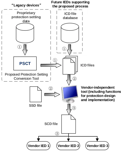
The existing IED configuration process, as defined in IEC 61850-6, is illustrated in Fig. 5 [16] and fully described in [9]. The main disadvantage of this process is that it involves many steps and various proprietary software tools (such as a vendor-independent system configuration tool and various vendor-specific IED configuration tools), requiring additional training and experience for protection engineers. This adds un-necessary complication to the implementation of a coordinated protection, automation, or control scheme where the details of each IED type must be considered [1], [13], [14].
the entire IED configuration process. The vendor-independent system configuration tool performs both system-level config-uration and the selection of protection settings. The System Configuration Description (SCD) file, containing protection settings data, is uploaded directly to each IED, and each IED retrieves and applies the protection settings automatically.
The proposed approach is significantly streamlined com-pared with the existing process and eliminates the reliance on proprietary software. The task of configuring multi-vendor systems is thereby simplified significantly, hence offering a more efficient solution for the engineering process. Existing proprietary legacy data can be integrated into the process automatically through the use of PSCT, which avoids signif-icant laborious manual input during the engineering process. Depending on the capability of the IEDs receiving the con-verted SCL-based setting data, some information may be lost or further manual configuration of the IEDs may be required (similar to the reverse mapping process described in Section III-B). The proposed process addresses CIGRE WG B5.31 and WG B5.50’s recommendations of taking full advantage of IEC 61850 for future protection settings management and a vendor-independent engineering process, including the representation of protection settings. In particular, the use of a common protection settings format, which is semantically well-defined and can be readily serialized to a text-based XML file, facilitates version management.
It is important to note that the proposed approach represents an ultimate solution for addressing the difficulties associated with multi-vendor systems. In the proposed process, IEDs are required to interpret protection settings from SCD files, but this functionality not currently available in most IEDs as deployed. This functionality could be added to existing IEDs through a firmware update issued by the IED vendor. Alternatively, ven-dors' IED configuration software could be updated to accept SCL-based settings files with the methodology proposed in this paper. This still requires vendor-specific software, but it avoids proprietary data formats, which is generally beneficial to the users. In any case, the work presented in this paper supports both approaches and minimizes the manual effort required.
B. Enabling protection settings for intelligent applications
The use of proprietary protection settings data formats does not usually permit access to, or manipulation of, these data by other software applications for automatic analysis of protection systems. PSCT provides a solution to this problem. The generated SCL-based settings format can be readily interpreted by external software applications.
For example, one of the main motivations of the work presented in this paper is the challenge of implementing an intelligent system for protection settings validation [33], [34], that must operate using a large variety of proprietary settings data formats. The settings validation system introduced in [33] contains a rule-based module based upon rules that have been predefined from a utility’s setting policies and from experts' knowledge that can characterize the validity of protection settings. While the majority of the knowledge used to define the rules is broadly similar, specific sets of rules must be
Writing protection
settings
Vendor IED 1
Writing protection
settings
Writing protection
settings ICD file
database ICD files
SCD file
SSD File
①
①
② ②
③
③
④ ④ ④
Vendor-specific IED configuration tools
Vendor-independent system configuration
tools
[image:6.612.328.546.57.239.2]Vendor IED 2 Vendor IED 3
Fig. 5. Existing IED configuration process defined in IEC 61850-6
Vendor IED 2
ICD file database
SCD file SSD file
①
②
③
Proprietary protection setting
data
PSCT ①
①
②
③
ICD files
Vendor IED 1 Vendor IED 3
Proposed Protection Setting Conversion Tool
“Legacy devices” Future IEDs supporting the proposed process
Vendor-independent tool (including functions for protection design and implementation)
Fig. 6. Simplified IED configuration process [9]
defined for each relay type. If the setting policies are changed, it is very laborious to update the system. This introduces a significant burden on the development and maintenance of the validation system.
By storing protection setting data in a standardized format, rules can be defined using a common, as opposed to pro-prietary, representation of protection settings. The number of rules that must be included is significantly reduced. Updating rules that are based on a common representation format is also much simpler, i.e. there is no need to retrospectively update rules for each relay type separately, since all relays utilize a single common format.
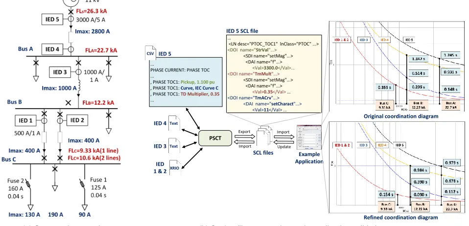
[image:6.612.331.543.280.545.2](a) Case study network
...
PHASE CURRENT: PHASE TOC ...
, PHASE TOC1: Pickup, 1.100 pu , PHASE TOC1: Curve, IEC Curve C , PHASE TOC1: TD Multiplier, 0.35 ...
…
<LN desc="PTOC_TOC1" lnClass="PTOC" ...> <DOI name="StrVal"...>
<SDI name="setMag"...> <DAI name="f"...>
<Val>3300.0</Val>...
<DOI name="TmMult"...> <SDI name="setMag"...>
<DAI name="f"...> <Val>0.35</Val> … <DOI name="TmACrv"...>
<DAI name="setCharact"...> <Val>11</Val> ...
PSCT
SCL files IED 5
Example Application
Original coordination diagram
Refined coordination diagram IED 5 SCL file
CSV
Text
IED 4
Text
IED 3
XRIO
IED 1 & 2
Export
Update Import
Import
[image:7.612.66.545.70.301.2](b) Setting files conversion and coordination validation process
Fig. 7. Overview of the multi-vendor overcurrent coordination demonstration
other potential applications of automatic protection system analysis and design, including: protection testing [6], event and disturbance analysis [4], [5], protection coordination [35], and protection diagnostics and simulation [36]. Furthermore, adaptive protection schemes would also be significantly more practical to implement with standardized settings [8].
V. CASESTUDY: COORDINATION OF AMULTI-VENDOR
OVERCURRENTPROTECTIONSCHEME
A. Overview of the case study
For an overcurrent protection scheme, it is important to ensure faults are cleared quickly, while maintaining coordi-nation with neighboring protection devices. Validating these schemes is becoming increasing challenging due to presence of distributed generation and smart grid implementations. Presently, validation requires systematic calculation of devices' operating times for faults at various locations to check whether coordination is achieved. The main purpose of this case study is not to demonstrate the coordination function itself in full detail, but the ease and convenience in data handling when the data are represented in the standardized format. The process can be difficult to perform automatically due to the proprietary protection settings formats used. In this case study, the proprietary setting files are converted to common SCL-based files using PSCT for automatic analysis and validation of the overcurrent protection coordination. The distribution network used in this case study is shown in Fig. 7a. The scenario presented here is based on the example documented in [37]. Five IEDs from three different vendors are considered [18], [19], [21]. The coordination constraints of the overcurrent protection scheme are summarized in Table I.
B. Converting proprietary setting files to SCL-based file
As shown in Fig. 7b, the IEDs' settings are stored in a number of proprietary formats: CSV, plain text, and XRIO. These files have been imported into PSCT and converted to SCL-based files, which have been successfully validated using EMF and the validator described in [27]. Fig. 7b shows a segment of IED 5's CSV-based settings file and the resultant SCL-based file. Another example is shown in Fig. 8, which shows the conversion of IED 1's XRIO-based settings file.
It is clear that the proprietary files have different data formats and use vendor-specific data models to represent protection settings. This means that the manipulation of these files has to be performed in an IED-specific manner, which is clearly a challenge for the development and maintenance of intelligent applications. However, SCL-based settings files are readily accessible for manipulation by generic vendor-independent software. The associated mapping details of a selection of IED 1 and IED 5 settings to IEC 61850 data objects in the PTOC logical node are documented in Table II and Table III.
C. Manipulating the SCL-based files for coordination valida-tion and optimizavalida-tion
[h]
<Parameter Id="ID_35_04"> <Name>I>1 Current Set</Name>... <Value>1240</Value>…
<Parameter Id="ID_35_06"> <Name>I>1 TMS</Name>... <Value>1</Value>… <Parameter Id="ID_35_02">
<Name>I>1 Function</Name>... <Value>ID_35_02_3</Value>... <EnumList>
<EnumValue EnumId="ID_35_02_3"> IEC E Inverse
</EnumValue> ...
…
<DOI name="StrVal"...> <SDI name="setMag"...>
<DAI name="f"...> <Val>620</Val>...
<DOI name="TmMult"...> <SDI name="setMag"...>
<DAI name="f"...> <Val>1</Val> … <DOI name="TmACrv"...>
<DAI name="setCharact"...> <Val>12</Val> ... IED 1
IED 1 SCL file XRIO file
[image:8.612.318.557.81.135.2] [image:8.612.348.531.196.256.2]Fig. 8. Conversion of a XRIO file to an SCL-based setting file
TABLE I
OVERCURRENT COORDINATION CONSTRAINTS Constraints
1 Time margin between IEDs and fuses:≥0.15s 2 Time margin between IEDs:≥0.3s
3 Current setting of IEDs:
≥105%Max load;
≥3×Largest downstream fuse rating. 4 IED 1, 2, 3:IEC Extremely Inverse;
IED 4, 5:IEC Standard Inverse.
TABLE II
MAPPING OFIED 1’S SETTINGS TOIEC 61850DATA OBJECTS
Proprietary IEC 61850
Current setting Current Set 1240 mA StrVal 620 A
Curve type Function IEC E Inverse TmACrv 12
Time multiplier TMS 1 TmMult 1
Note:
1)Current Setis represented in secondary value;
2)TmACrvwith a value of “12” stands forIEC Extremely Inverse.
is also desirable that all the curves are shifted downward for a reduced operating time, with associated benefits to operating safety.
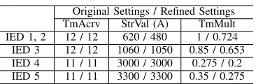
The settings have been refined, by referencing the common data model, and these refined settings are listed in Table IV. The coordination diagram using the refined settings is shown in the bottom-right of Fig. 7b which shows that coordination is maintained while the overall operating times have been reduced. To update the IEDs’ settings, the data in SCL files are converted back to the proprietary formats and applied to the corresponding IEDs manually, because existing IEDs typically do not allow importing the settings automatically - this is indeed a problem that the paper addresses. As proposed in Section IV-A, this step can be avoided if vendors provide new IED firmware or configuration software to accept the SCL-based settings directly.
Developing intelligent applications that require manipula-tion of multiple vendors' settings files is clearly challenging. The case study shows that this problem can be addressed using the common representation of protection settings proposed in this paper. This provides significant benefits: convenience for network operators and system integrators, and confidence in the validity of protection settings due to the avoidance of manual input.
TABLE III
MAPPING OFIED 5’S SETTINGS TOIEC 61850DATA OBJECTS
Proprietary IEC 61850
Current setting Pickup 1.10 pu StrVal 3300 A
Curve type Curve IEC Curve A TmACrv 11
Time multiplier
TD
Multiplier 0.35 TmMult 0.35
Note:
1)Pickup:Ibase= 3000A;
2)TmACrvwith a value of “12” stands forIEC Standard Inverse.
TABLE IV
ORIGINAL AND REFINEDIEC 61850-BASED SETTINGS Original Settings / Refined Settings
TmAcrv StrVal (A) TmMult
IED 1, 2 12 / 12 620 / 480 1 / 0.724
IED 3 12 / 12 1060 / 1050 0.85 / 0.653 IED 4 11 / 11 3000 / 3000 0.275 / 0.2 IED 5 11 / 11 3300 / 3300 0.35 / 0.275
VI. DISCUSSION ANDCONCLUSIONS
The management and engineering of modern protection systems is clearly a complex and challenging task due to the very large number of parameters and the present need to use various vendor-specific software tools. The shift towards vendor-independent, open data formats has been recognized as offering advantages for protection systems by several CIGRE and IEEE working groups. However, it has proved difficult to realize these advantages, due to the wide array of legacy devices and proprietary tools which are inherent within present networks and processes. This paper has addressed this chal-lenge by presenting the design of the PSCT, which translates proprietary settings formats to the IEC 61850 SCL format. The paper has demonstrated the use of the PSCT software to automatically convert, bi-directionally, between proprietary settings data from various vendors and the proposed common format. The key advancement is the code generation module within PSCT, which means only minimal manual configuration is required when support for a new type of IED is added.
The advantages of using a common representation for protection settings have been highlighted in the paper, and two applications and their associated benefits have been demon-strated and discussed. It has been shown that the SCL-based protection settings format is easier to interpret and manipulate using software, which significantly reduces the burden of designing, implementing, and maintaining protection schemes. A novel IED configuration process using the proposed ap-proach has been developed, which is streamlined and more efficient compared to existing approaches. The integration of legacy data within the proposed engineering process is largely automated with the aid of PSCT. Examples have been given which demonstrate the manipulation of existing protection settings data from multiple vendors, and translation of existing protection settings data to a common representation. The PSCT software presented in this paper provides evidenced support for network operators to adopt the proposed approach.
61850 has been extended to represent protection settings data; the newly developed IED configuration process has integrated the engineering process and protection setting process; the version management of protection settings becomes signifi-cantly easier when the data are represented in a common SCL-based format; and the PSCT provides enhanced support for protection settings data access, exchange, and manipulation by various stakeholder groups. The work also addresses IEEE PSRC WG H5, H27 and CIGRE WG B5.27's recommen-dations relating to requirements for a common format of protection settings.
On-going and future work is concerned with the develop-ment of an intelligent system for protection settings validation. This work is made significantly easier using a common for-mat for protection setting data and the implemented PSCT software.
REFERENCES
[1] J. Sykes, V. Madani, J. Burger, M. Adamiak, and W. Premerlani, “Reliabilty of protection systems (what are the real concerns),” in
Protective Relay Engineers, 2010 63rd Annual Conference for, March
2010, pp. 1–16.
[2] IEC TC 57, “IEC 61850-1: Introduction and overview,” 2003. [3] A. McMorran, G. Ault, C. Morgan, I. Elders, and J. R. Mcdonald, “A
common information model (cim) toolkit framework implemented in java,”Power Systems, IEEE Transactions on, vol. 21, no. 1, pp. 194– 201, Feb 2006.
[4] A. Apostolov, “Event and Disturbance Analysis-Common Data For-mats,”Pacworld Magazine, pp. 47–51, Jun 2013.
[5] ——, “Disturbance analysis for the 21st century,”Pacworld Magazine, p. 4, June 2013.
[6] A. Apostolov and B. Vandiver, “On the standardization of distance characteristics,” in Power Systems Conference: Advanced Metering, Protection, Control, Communication, and Distributed Resources, 2007.
PSC 2007, March 2007, pp. 209–212.
[7] IEEE Power System Relaying Committee Working Group H5, “Common Format for IED Configuration Data,” IEEE, Tech. Rep., 2013. [8] F. Coffele, S. Blair, C. Booth, J. Kirkwood, and B. Fordyce,
“Demon-stration of adaptive overcurrent protection using IEC 61850 communi-cations,” inElectricity Distribution (CIRED 2013), 22nd International Conference and Exhibition on, June 2013, pp. 1–4.
[9] Q. Hong, S. Blair, V. Catterson, A. Dysko, C. Booth, and T. Rahman, “Standardization of power system protection settings using IEC 61850 for improved interoperability,” inPower and Energy Society General Meeting (PES), 2013 IEEE, July 2013, pp. 1–5.
[10] G. Huon, A. Apostolov, R. Paulo et al, “IEC61850 Based Substation Automation Systems Users Expectations and Stakeholders Interactions,” inCIGRE Paris Session, 2014.
[11] A. Apostolov, “Simplifying the configuration of multifunctional distri-bution protection and control ieds,” in Electricity Distribution, 2005.
CIRED 2005. 18th International Conference and Exhibition on, June
2005, pp. 1–4.
[12] E3 - Spanish Electricity Companies for Studies on IEC 61850, “Mini-mum common specification for substation protection and control equip-ment in accordance with the IEC 61850 standard,” June 2010. [13] N. Burnham, “Network Rail and IEC 61850, a user’s perspective of the
standard,” inDevelopments in Power Systems Protection, 2012. DPSP 2012. 11th International Conference on, April 2012, pp. 1–5. [14] X. Zhao, L. Li and G. Huon, “CIGRE 2014 Group 5 (Protection
and Automation) Discussion Meeting Summary (2014 CIGRE Paris Session),” August 2014.
[15] ENTSO-E, “ENTSO-E statement on the IEC 61850 standard,” 2012. [16] IEC TC 57, “IEC 61850-6: Configuration description language for
communication in electrical substations related to IEDs,” 2010. [17] Siemens, “SIPROTEC 5 IEC 61850 Manual,” 2013.
[18] ABB, “Line distance protection REL670 Technical reference manual,” 2012.
[19] AlstomGrid, “MiCOMho P443, P445 Technical Manual,” 2011. [20] ——, “MiCOM P543, P544, P545, P546 Technical Manual,” 2011. [21] GE Digital Energy, “D60 Line Distance Protection System UR Series
Instruction Manual,” 2012.
[22] IEC TC 57, “IEC 61850 7-4: Basic communication structure Compatible logical node classes and data object classes,” 2010.
[23] ——, “IEC 61850-7-3: Basic communication structure Common data classes,” 2010.
[24] IEEE Power System Relaying Committee Working Group H27, “Power System Relaying Committee Working Group H27 Common Format for Relay Settings Data,” 2014. [Online]. Available: http://www.pes-psrc.org/h/h27/h27.html
[25] Omicron, “XRIO User Manual,” 2011.
[26] W3C, “XML Schema,” 2014. [Online]. Available:
http://www.w3.org/XML/Schema
[27] S. Blair, F. Coffele, C. Booth, and G. Burt, “An open platform for rapid-Prototyping protection and control schemes with IEC 61850,” Power Delivery, IEEE Transactions on, vol. 28, no. 2, pp. 1103–1110, April 2013.
[28] CIGRE Working Group B5.27, “Implications and Benefits of Standard-ised Protection and Control Schemes,” CIGRE, Tech. Rep., 2014. [29] CIGRE Working Group B5.31, “Life-time Management of Relay
Set-tings,” CIGRE, Tech. Rep., 2013.
[30] Oracle, “Java,” 2014. [Online]. Available: http://java.com/en/
[31] Eclipse Foundation, “Eclipse Modeling - EMF - Home,” 2014. [Online]. Available: http://www.eclipse.org/modeling/emf/
[32] A. McMorran, G. AuIt, I. Elders, C. Foote, G. Burt, and J. McDonald, “Translating cim xml power system data to a proprietary format for system simulation,” in Power Engineering Society General Meeting, 2004. IEEE, June 2004, pp. 116 Vol.1–.
[33] Q. Hong, A. Dysko, and C. Booth, “Intelligent system for detecting hidden errors in protection settings,” inUniversities Power Engineering Conference (UPEC), 2012 47th International, Sept 2012, pp. 1–6. [34] Q. Hong, A. Dysko, C. Booth, V. Catterson, S. Blair, and T. Rahman,
“Translating proprietary protection setting data into standardised IEC 61850 format for protection setting validation,” in Developments in Power System Protection (DPSP 2014), 12th IET International Con-ference on, March 2014, pp. 1–6.
[35] C. So and K. Li, “Time coordination method for power system protection by evolutionary algorithm,”Industry Applications, IEEE Transactions on, vol. 36, no. 5, pp. 1235–1240, Sep 2000.
[36] E. Davidson, S. McArthur, and J. McDonald, “A toolset for applying model-based reasoning techniques to diagnostics for power systems protection,”Power Systems, IEEE Transactions on, vol. 18, no. 2, pp. 680–687, May 2003.