1234567890 ‘’“”
9th International Particle Accelerator Conference, IPAC18 IOP Publishing IOP Conf. Series: Journal of Physics: Conf. Series 1067 (2018) 042011 doi :10.1088/1742-6596/1067/4/042011
Two-stage laser-driven plasma acceleration with external
injection for EuPRAXIA
E N Svystun1, R W Assmann1, U Dorda1, A Ferran Pousa1,2, T Heinemann1,2,3, B Marchetti1, A Martinez de la Ossa2, P A Walker1, M K Weikum1 and J Zhu1 1Deutsches Elektronen-Synchrotron, DESY, 22607 Hamburg, Germany
2University of Hamburg, 20148 Hamburg, Germany
3SUPA, Department of Physics, University of Strathclyde, Glasgow G4 0NG, UK
Email address: [email protected]
Abstract. The EuPRAXIA (European Particle Research Accelerator with eXcellence In Applications) project aims at producing a conceptual design for the worldwide plasma-based accelerator facility, capable of delivering multi-GeV electron beams with high quality. This accelerator facility will be used for various user applications such as compact X-ray sources for medical imaging and high-energy physics detector tests. EuPRAXIA explores different approaches to plasma acceleration techniques. Laser-driven plasma wakefield acceleration with external injection of an RF-generated electron beam is one of the basic research directions of EuPRAXIA. We present studies of electron beam acceleration to GeV energies by a two-stage laser wakefield acceleration with external injection from an RF accelerator. Electron beam injection, acceleration and extraction from the plasma, using particle-in-cell simulations, are investigated.
1. Introduction
The remarkable progress in laser technology over the past decade [1, 2] allows Laser-plasma accelerators (LPA) to be seen as the leading technology in advanced accelerators standing out through enormous accelerating gradients on the order of 10-100 GV/m [3]. However, despite prominent experimental and theoretical achievements in the field of laser wakefield acceleration (LWFA), among others the demonstration of the production of GeV-class electron beams [4, 5], the realization of a LPA matching the demanding requirements on beam quality and stability for applications such as Free-Electron-Lasers (FEL) remains a challenge. Key parameters of electron beams delivered by LPAs, such as energy spread and normalized emittance, are still worse than those achieved in conventional accelerators. Limitations on the quality of laser-plasma-accelerated electron beams may arise from laser instabilities, plasma density fluctuations, scarce control over the beam injection process, etc.
1234567890 ‘’“”
9th International Particle Accelerator Conference, IPAC18 IOP Publishing IOP Conf. Series: Journal of Physics: Conf. Series 1067 (2018) 042011 doi :10.1088/1742-6596/1067/4/042011
In this paper, we present an extension of numerical studies reported in [6] on quality-preserving acceleration of an electron beam by a laser-driven plasma accelerator with external injection from an RF linac. These studies have been carried out in the context of EuPRAXIA [7]. The Horizon 2020 project EuPRAXIA is preparing a conceptual design report of a highly compact and cost-effective plasma-based European facility with multi-GeV electron beams.
2. Results and discussion
Previous studies [6] for the first set of EuPRAXIA laser pulse parameters and a plasma density of n0 = 1017cm-3showed that the laser pulse defocusing starts to play a considerable role at distances of
the order of 2-3 cm, thus limiting the length of the acceleration region. Another factor that limits the acceleration process in LPAs is laser diffraction, the characteristic distance of which is the Rayleigh length:
where 0 is the laser spot size at the focus and is the laser wavelength.
In the studies presented in this paper, the laser pulse defocusing and diffraction were counteracted by transverse plasma density tailoring, that allowed the laser pulse to be guided. This in turn enabled the acceleration region to be extended to lengths greater than the Rayleigh length, and the laser pulse energy and power to be reduced.
A two-dimensional simulation has been carried out with the particle-in-cell (PIC) code OSIRIS [8]. The following laser pulse parameters were assumed: pulse length = 70 fs (FWHM); spot size
0 = 50 μm; normalized peak intensity 0 = 2.7; wavelength = 800 nm; peak power ≈ 612 TW. The laser transverse and temporal profiles are Gaussian. The laser pulse and the electron beam are injected collinearly into a plasma channel with a radially parabolic density profile of the form
r= +Δr, wherethe channel depth Δ = 0.452, the channel width = 50 μm and the on-axis plasma density = 1017 cm−3. The plasma wavelength is = 106 μm and the plasma skin depth is = !" = 16.8 μm, with the plasma frequency given by = (#$%#&, where is the speed of light, is the plasma wave number, # is the electron charge, $ is the vacuum permittivity and %# is the electron mass. The temporal offset between the electron beam center and the laser pulse center is equal to 294 fs (88.22 μm).
The simulation was conducted by employing a speed-of-light moving window with the longitudinal and transverse sizes of (11 × 20)!" and a resolution of (0.00095 × 0.0588)!". The time step is 0.000932082'!" ≈ 52.25 as, corresponding to a length of 15.66 nm. The number of particles per cell is 4 for the plasma and 256 for the witness electron beam. To eliminate an artificial growth in electron beam emittance caused by numerical Cherenkov radiation (NCR) generated in the standard Yee field solver, a special NCR-suppressing solver [9] has been used for electromagnetic field calculations.
The parameters of the externally injected witness beam used in the simulation are defined based on the results of simulations [10] for the future ARES-linac at the SINBAD facility at the DESY Hamburg campus [11]. A full set of initial beam parameters is given in Table 1. An initial symmetric Gaussian distribution in coordinate and momentum space is assumed for the injected beam.
In PBAs, transverse matching of injected electron beams into the plasma focusing fields is vital for beam emittance growth control. Tailoring the longitudinal density profile of the plasma entrance and exit with smooth vacuum-plasma and plasma-vacuum transitions can be used to minimize the induced emittance growth during beam acceleration and extraction, as shown in [12 - 14]. In the considered case the following longitudinal plasma density profile for up- and down-ramps was implemented:
( & ) * &
1234567890 ‘’“”
[image:3.595.156.442.105.231.2]9th International Particle Accelerator Conference, IPAC18 IOP Publishing IOP Conf. Series: Journal of Physics: Conf. Series 1067 (2018) 042011 doi :10.1088/1742-6596/1067/4/042011
Table 1. Electron beam parameters at the plasma entrance.
Charge, Q [pC] 5.6
Mean energy, /0 [MeV] 101
Relative energy spread, Δ//0 [%] 0.43
Longitudinal RMS size,σz;rms [μm] 0.59
Transverse RMS size,σx;rms [μm] 2.55
Beta-function,βx [mm] 2.76
Normalized transverse emittance, εn;x [μm] 0.47
Here - and + are the longitudinal coordinates of the start of the up-ramp and the down-ramp respectively; - and + are the optimized characteristic scale lengths of the plasma ramps given by
+,- 1 236714 5 & 89:1;<
5& =
+,-189:1;* &
where 1 is the beta function of the matched electron beam in PBAs, 1 >?@%AB#, with ?@ being the beam Lorentz factor and B being the transverse focusing field in the plasma; 1; is the initial beta function of the beam; 189: is the beta function of the beam matched to the plasma section in the case of the plasma up-ramp and to the external focusing elements in the case of the down-ramp; N = 0, 1, 2, …; - and + are the lengths of the plasma up-ramp and the down-ramp respectively. Such tailoring of the longitudinal density profile was analytically and numerically investigated in [14] for PBAs operating in the nonlinear regime and can be experimentally realized in appropriate gas capillaries [15].
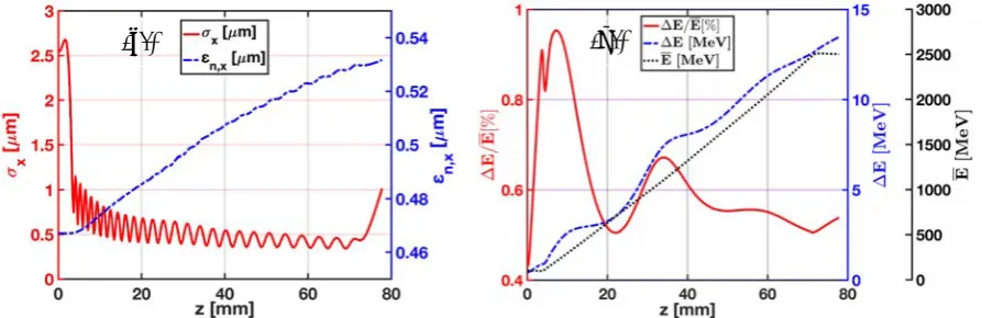
Simulation results and longitudinal plasma profile parameters are summarized in Table 2. The evolution of the normalized transverse emittance, transverse RMS size, mean energy, relative energy spread and absolute energy spread of the electron beam during injection, acceleration and extraction from the plasma is presented in Fig. 1.
Table 2. Longitudinal plasma profile parameters and properties of the accelerated electron beam after extraction from the plasma.
Charge, Q [pC] 5.6
Peak current [kA] 1.1
Mean energy, /0 [MeV] 2503
Relative energy spread, Δ//0 [%] 0.54 Relative slice energy spread [%] 0.022
Longitudinal RMS size,σz;rms [μm] 0.59
Transverse RMS size,σx;rms [μm] 0.98
Normalized transverse emittance, εn;x [μm] 0.53
Normalized slice emittance, εn;x [μm] 0.49
Lu [mm] / lu [mm] 3.85 / 0.52
Acceleration region length [mm] 67.22
Ld [mm] / ld [mm] 6.46 / 2.18
[image:3.595.150.445.499.728.2]1234567890 ‘’“”
[image:4.595.79.526.96.241.2]9th International Particle Accelerator Conference, IPAC18 IOP Publishing IOP Conf. Series: Journal of Physics: Conf. Series 1067 (2018) 042011 doi :10.1088/1742-6596/1067/4/042011
Figure 1. Evolution of the externally injected electron beam properties during acceleration to 2.5 GeV. Left panel (a): transverse RMS beam size (red solid curve); normalized transverse emittance (blue dashed curve). Right panel (b): relative energy spread (red solid curve); absolute energy spread (blue dashed curve); mean energy (black dotted curve).
The results show that the use of a short plasma up-ramp at the beginning of the plasma allows the initial transverse size of the injected beam to be decreased to a value close to the matched one, as shown in Fig. 1 (a). Due to the imperfect matching, the accelerated electron beam develops a decoherence of particle betatron oscillations and beam envelope oscillations [16, 17] from the end of the plasma up-ramp, consequently leading to a small growth in transverse emittance with a rate of approximately 9 nm/cm. Therefore, the use of short plasma ramps, 3.85 mm in length at the beginning of the plasma and 6.46 mm at the plasma exit, provides sufficient control over the emittance growth throughout the propagation distance.
The energy spread of accelerated electron beams is determined to a considerable extent by the gradient of the longitudinal wakefield acting on them. In the present case, due to the short duration (σz;rms ≈ 2 fs) and high density (b = 5.7×1017 cm−3) of the electron beam, it creates its own wakefield,
the beam loading field [18, 19], of the same order of magnitude as the gradient of the laser-excited plasma wakefield at the region occupied by the beam. Injection of the electron beam into a proper wave phase can allow the laser-driven wakefield to be compensated by the beam loading field, consequently leading to a mitigation of the energy spread growth during the acceleration process. As shown in Fig. 1 (b), throughout the up- and down-ramps the beam energy spread increases, as in regions of low density the beam loading field prevails over the laser-excited wakefield. The relative energy spread decreases in regions where the effective laser wakefield is flattened by the beam loading field, while the absolute energy spread stays near constant. However, in our case, periodical self-focusing and defocusing of the laser pulse are observed during its propagation through the parabolic plasma channel. This leads to periodic changes in the laser-excited wakefield amplitude and shape, and as a consequence, to a reduction of beam loading compensation due to the imperfect flattening of the field at the beam position.
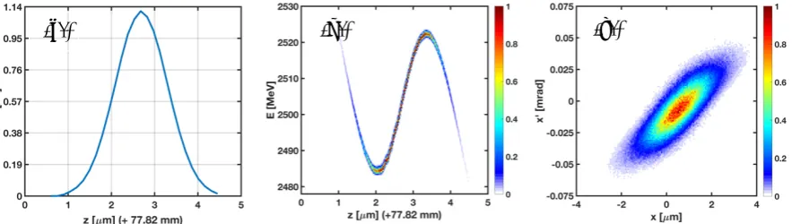
Based on the above, the final properties of the accelerated electron beam are very promising (see Table 2) and meet the requirements of demanding applications such as FELs. The current distribution, as well as longitudinal and transverse phase-spaces of the accelerated electron beam after its extraction from the plasma are presented in Fig. 2.
We should note that a number of factors may have some effect on the results of the simulation. Numerical electron beam-laser dephasing of 12.17 μm (11 % of the plasma wavelength), observed in the simulations due to the superluminal group velocity of the laser pulse in the NCR-suppressing field solver [9], may affect the evolution of the electron beam properties to a small extent. Furthermore, a longitudinal energy chirp and beam asymmetry in the transverse plane, observed in the simulations for
1234567890 ‘’“”
9th International Particle Accelerator Conference, IPAC18 IOP Publishing IOP Conf. Series: Journal of Physics: Conf. Series 1067 (2018) 042011 doi :10.1088/1742-6596/1067/4/042011
the ARES linac and not considered here, may have some influence on the evolution of the beam properties. 3D simulations with the full 6D phase space beam distribution are planned to examine these effects.
3. Conclusions
The successful quality-preserving acceleration of an externally injected beam by a laser wakefield accelerator was demonstrated through a two-dimensional PIC simulation. After extraction from the plasma the electron beam has very promising properties for FEL applications: mean energy of 2.5 GeV, beam RMS-duration around 2 fs, peak current of 1.1 kA, slice energy spread of 0.022 % and slice normalized transverse emittance of 0.49 μm.
It is planned to extend the presented studies on quality-preserving acceleration to electron beams with higher charges taking into account also the full 6D phase space beam distribution.
Acknowledgements
We would like to acknowledge the OSIRIS Consortium (IST/UCLA) for providing access to the OSIRIS code. This work was supported by the European Union’s Horizon 2020 research and innovation programme under grant agreement № 653782.
References
[1] Haefner C L et al 2017 High average power, diode pumped petawatt laser systems: a new generation of lasers enabling precision science and commercial applications Proc. SPIE Optics + Optoelectronics: Research Using Extreme Light: Entering New Frontiers with Petawatt-Class Lasers III vol 10241, ed G Korn and L O Silva (SPIE Digital Library) p 1024102 https://doi.org/10.1117/12.2281050
[2] Nakamura K, Mao H-S, Gonsalves A J, Vincenti H, Mittelberger D E, Daniels J, Magana A, Toth C and Leemans W P 2017 Diagnostics, Control and Performance Parameters for the BELLA High Repetition Rate Petawatt Class Laser EEE J. Quantum Electron53 (4) 1200121 https://doi.org/10.1109/jqe.2017.2708601
[3] Esarey E, Schroeder C B and Leemans W P 2009 Physics of laser-driven plasma-based electron accelerators Rev. Mod. Phys. 81 1229
[4] Leemans W P et al 2014 Multi-GeV electron beams from capillary-discharge-guided subpetawatt laser pulses in the self-trapping regime Phys. Rev. Lett. 113 245002
[5] Gonsalves A J et al 2015 Generation and pointing stabilization of multi-GeV electron beams from a laser plasma accelerator driven in a pre-formed plasma waveguide Phys. Plasmas22 056703 [6] Svystun E N et al 2018 Beam quality preservation studies in a laser-plasma accelerator with
[image:5.595.83.525.95.220.2]external injection for EuPRAXIA Nucl. Instr. Meth. A, In press https://doi.org/10.1016/j.nima.2018.02.060
Figure 2. Current distribution (a), longitudinal (b) and transverse (c) phase-spaces of the accelerated electron beam after its extraction from the plasma target. The colormap describes normalized charge.
1234567890 ‘’“”
9th International Particle Accelerator Conference, IPAC18 IOP Publishing IOP Conf. Series: Journal of Physics: Conf. Series 1067 (2018) 042011 doi :10.1088/1742-6596/1067/4/042011
[7] Walker P A et al 2017 Horizon 2020 EuPRAXIA design study J. Phys.: Conf. Ser. 874 012029 [8] Fonseca R A et al 2002 OSIRIS: a three-dimensional, fully relativistic particle in cell code for
modeling plasma based accelerators (Lecture Notes in Computer Science) vol 2331 (Berlin: Springer) p 342
[9] Lehe R, Lifschitz A, Thaury C and Malka V 2013 Numerical growth of emittance in simulations of laser-wakefield acceleration Phys. Rev. ST Accel. Beams16 021301
[10] Zhu J, Assmann R, Dorda U and Marchetti B 2018 Lattice design and start-to-end simulations for the ARES linac Nucl. Instr. Meth. A, In press
https://doi.org/10.1016/j.nima.2018.02.045
[11] Dorda U et al 2017 The Dedicated Accelerator R&D Facility Sinbad at DESY Proc. 8th Int. Particle Accelerator Conf. (IPAC'17)(Copenhagen, Denmark), ed G Arduini, M Lindroos et al (The Joint Accelerator Conferences Website: JACoW) paper MOPVA012 pp 869-872 http://dx.doi.org/10.18429/JACoW-IPAC2017-MOPVA012
[12] Floettmann K 2014 Adiabatic matching section for plasma accelerated beams Phys. Rev. ST Accel. Beams17 054402
https://doi.org/10.1103/PhysRevSTAB.17.054402
[13] Dornmair I, Floettmann K and Maier A R 2015 Emittance conservation by tailored focusing profiles in a plasma accelerator Phys. Rev. ST Accel. Beams18 041302
[14] Xu X L et al 2016 Physics of phase space matching for staging plasma and traditional accelerator components using longitudinally tailored plasma profiles Phys. Rev. Lett. 116 124801
[15] Schaper L et al 2014 Longitudinal gas-density profilometry for plasma-wakefield acceleration targets Nucl. Instr. Meth. A740 208
https://doi.org/10.1016/j.nima.2013.10.052
[16] Marsh K A et al 2005 Beam Matching to a Plasma Wake Field Accelerator using a Ramped Density Profile at the Plasma Boundary Proc. 2005 Particle Accelerator Conf. (Knoxville, Tennessee, USA), edC Horak(IEEE, Piscataway, NJ) pp 2702–2704
https://doi.org/10.1109/PAC.2005.1591234
[17] Khachatryan A G, Irman A, van Goor F and Boller K-J 2007 Femtosecond electron-bunch dynamics in laser wakefields and vacuum Phys. Rev. ST Accel. Beams10 121301
https://doi.org/10.1103/PhysRevSTAB.10.121301
[18] van der Meer S 1985 Improving the power efficiency of the plasma wakefield accelerator CERN-PS-85-65-AA CLIC-Note-3 pp 1-7