Robotic shaping of a thin rheological material over a moulding object
– Modeling and experimental validation
Silvio Cocuzza
a,*, Xiu-Tian Yan
aaDepartment of Design, Manufacture and Engineering Management, University of Strathclyde, 75 Montrose Street, Glasgow G1 1XJ, United Kingdom
*Corresponding author
E-mail address: [email protected]
Abstract
In view of the automatic manipulation and shaping of rheological objects, e.g. food material or biological tissues, the need of modeling and characterizing the material from an engineering point of view and of constructing a dynamic model of the whole rheological object arise. In this paper, a catenary-like Mass-Spring-Damper (MSD) model formed of lumped masses interconnected with three-element units is proposed to study and simulate the 2-D shaping of a thin rheological material over a moulding object. First, a three-step method for identifying the material properties from experimental tensile tests is proposed and validated. The method has allowed both to identify the material properties and to validate the three-element material model used, thanks to the close agreement between the material mathematical model and the experimental data. Then, a multibody model of the rheological object is proposed, which has been validated thanks to the close agreement between the simulated deformation profile and the experimental one in two test cases: in the first test case the rheological object deforms under the load of the gravity force only, and in the second one it is forced to deform by a shaping tool. Finally, the validated model is used in order to compare different shaping movements and velocities of the tool by dynamic simulations, with particular attention to the internal tensile force generated in the material - which has to be sufficiently far from the break - and the quality of the shaping operation which is directly related to the total non-recoverable deformation generated. A two-step shaping movement results more advantageous with respect to simpler motions since significantly reduced internal forces are generated in the material while the quality of the shaping operation is still guaranteed.
Keywords: Robotic shaping; Rheological material; Soft object; Deformation control; Material identification; Mass-spring-damper model.
1. Introduction
The problem of automatic manipulation and shaping of deformable objects has recently attracted the interest of many robotics researchers. This is due to economically important tasks that require the deformation control of soft objects in different application fields, e.g. in the food industry to automate the shaping of food materials [1], in surgical robotics [2, 3], or in the assembly of flexible objects [4].
One of the main issues that complicates the automation of these tasks is the estimation of the object deformation properties, which are needed to control its shape using the motion of a tool, usually actuated by a robot manipulator.
only be used for controlling the deformation of compliant bodies which can be approximated using a purely elastic model.
On the other hand, most of the food and biological materials exhibit a rheological behaviour, i.e. with both recoverable elastic (or viscoelastic) deformations and non-recoverable plastic deformations.
Many physically based models have been proposed to describe the dynamic properties of rheological materials, including the Maxwell, Kelvin-Voigt, three-element, and Burger models [8], and the four-element [9] and five-four-element [10] models.
A comprehensive study on rheological objects based on three main deformation properties – residual deformation, bouncing displacement, and vibration decrease – has been performed in [11]. In this study it has been concluded that a three-element model (i.e., a spring and a dashpot in parallel (Kelvin-Voigt element) with another dashpot element in series) gives an appropriate choice of rheological object modeling, which is also adopted in this work.
The mathematical modeling and properties estimation of rheological materials have been studied in several research papers. In many of these works [9, 11-17] the rheological object is modeled with 2-D or 3-D lattice structures and Mass-Spring-Damper (MSD) systems – usually a three-element material model is used – to connect the mass nodes. In some of these works, the shape of the rheological object is then calibrated with the experimentally measured deformations of the structure, using genetic algorithms [13, 14] or randomized algorithms [15, 16].
On the other hand, in [10, 18-21] the rheological object is modeled using a 2D or 3D Finite Element (FE) model, in which each element behaves like a rheological element (three-element, four-element, or five-element models have been used), obtaining a better deformation force accuracy with an increased computational cost [19]. In [20, 21] a three-element model is used, whereas in [10, 18, 19] four-element and five-element models have been introduced in order to have a better approximation of experimental forces and deformations. In most of these works the shape and deformation forces of the rheological object are then calibrated using experimentally measured forces and related
displacements using an inverse FE optimization approach, i.e. the FE simulation is iterated with updated physical parameters until the difference between the simulation and experiment results is minimized by using nonlinear least squares optimization. Methods to identify the physical parameters of rheological deformation based on 2-D FE dynamic equations [20] and based on the analytical force expression [18] have also been proposed.
Only few [17, 21] of the above cited works on the modeling of rheological objects with lattice structures or FE models use material properties which are directly determined by experimental tests (e.g., uniaxial compression or tensile tests of a material specimen). In particular, in [21] the material parameters are determined with tensile tests and the proposed FE model demonstrates a good
accuracy. Nevertheless, the model has been developed making important simplifying assumptions on the deformed shape and it has been experimentally validated only for a simple thick rectangular cross-section specimen loaded with compression forces. On the other hand, in [17] the material properties have been determined using a creep test (compression) of a thick specimen and the proposed lattice model shows some inaccuracies, and methods to improve the precision of the dynamic model with respect to the experimental data are discussed (but not validated) in the paper.
properties of a “Norimaki-sushi” modeled with a Burger model is presented in [22], which exploits measured forces and displacements in the closing phase of the grasping device. A method based on haptic vision to extract the rheological properties of a deformable object (with a thick rectangular cross-section) modeled with a three-element model is proposed in [23]. In [24], the rheological properties of different dough-like materials modeled with the three-element model are determined using the data of creep-recovery (compression) tests of cubic specimens. In this work, successive multi-trial solutions are used in order to achieve close agreement between predicted and measured response of the specimens to step change in force.
The robotic shaping of rheological objects has recently received an increasing interest by the robotics research community. The development of an automatic forming machine for food dough is reported in [1]. This paper proposes a control method based on a forming process model to give a desired 2-D shape to soft food dough. A model-based deformation control method for rheological objects is presented in [25]. In this work, the desired shape of the object is obtained by decomposing the deformation into elasticity and plasticity and using a two-phase control strategy: 1. offline material parameters identification, and 2. model-based control. However, this work only formulates the problem for a simple 1-D deformation, i.e. the compression of the body.
A robust controller to indirectly position multiple points of interest on a deformable object is reported in [26]. Nevertheless, the applicability of this method to rheological materials has not been discussed.
In [12], a model-based control method is presented to deform the shape of a 2-D rheological object (modeled using a MSD system and three-element material model) by multiple manipulators. In this work, which is only tested with numerical simulations, controlled forces are applied at the boundary contact points to create the desired object contour.
A dynamic nonprehensile shaping method of a thin rheological object is presented in [27], in which the object shape is dynamically controlled by the combination of the inertial and friction forces generated by the supporting plate rapid motion. This work is extended in [28] by allowing the object to jump from the plate surface to the air, while in the previous work the object was supposed to keep full-contact with the plate. By changing the contact mode, a potential to produce a larger deformation is given to the object.
It is worth noticing that, to control deformations with rheological materials, all the above presented shaping methods need a-priori knowledge of the material properties.
In this paper, a catenary-like MSD model formed of lumped masses interconnected with three-element units is proposed to simulate the 2-D shaping of a thin rheological material over a moulding object. To the best of authors’ knowledge, this is the first work in the literature in which the out-of-plane shaping of a thin rheological object is studied. Other papers [1, 12] presented methods to control the contour of a thin 2-D rheological object, and methods to extend or contract a thin rheological object are presented in [27, 28]. Nevertheless, in all of these works the rheological object deforms remaining in the plane in which it was originally.
1. free deformation of the rheological object loaded with the gravity force only, and 2. forced deformation with the shaping tool. Finally, the validated model is used in order to compare different shaping movements of the tool, with particular attention to the internal tensile force generated in the material (which has to be sufficiently far from the break) and the total non-recoverable deformation obtained in the shaping, which is related to the overall quality of the shaping operation (evaluated through the error between the obtained object profile and the desired shape).
It is worth noticing that in this work a different approach is used with respect to [9-16, 18-20] in which the material model is selected (but not directly validated), and then the experimental
displacements and shaping forces of the 2D or 3D object are used to calibrate the material properties. By skipping the direct validation of the material model, eventual inaccuracies due to a not correct material model could mix with inaccuracies introduced by the object model (e.g., the lattice of FE model). On the other hand, in this work (similarly to [17, 21], in which a similar approach has been used for thick rheological objects) first the material properties are identified (thus leading to the validation of the selected material model), and then the dynamic model of the rheological object is built using the identified material properties. Finally, the object model is validated using the experimental deformations of the object. By performing two separate validation phases, one for the material model, and another one for the object model, this approach is less vulnerable to modeling inaccuracies.
Moreover, to the best of authors’ knowledge, this paper is the only one in the literature that presents uniaxial tensile tests data and related identification of material properties (and validation of the material model) of a thin rheological material (fondant icing). Indeed, most of the works in the literature present identification methods of rheological material properties using data from compression tests of thick specimens [21-24], which is due to the fact that in most of the related works on mastication, grasping, and processing of food materials, usually compression forces are involved. Furthermore, this is the first work in the literature in which fondant icing is modeled as an engineering material, experimentally tested, its mechanical properties are identified, and its automated shaping is investigated.
The paper is structured as follows. Section 2 presents the material model. Section 3 reports the experimental setup, the experimental tensile test results, and the method used to identify the material properties. Section 4 presents the dynamic model of the thin rheological object and its validation. Section 5 discusses and compares different shaping procedures. Finally, Section 6 concludes the paper.
The material model and the identification of its properties presented in Sections 2 and 3.4 have been developed for a generic rheological material, which can be modeled with a three-element system. On the other hand, Sections 3.1-3.3, 5, and 6 have been developed for a particular rheological material (fondant icing); nevertheless, the methods and discussions can be straightforwardly applied to a generic rheological material.
2. Rheological materialmodel
Most of the food and biological materials exhibit a rheological behaviour, i.e. with both recoverable elastic (or viscoelastic) deformations and non-recoverable plastic deformations, when they are handled and processed.
The three-element model (i.e., a spring and a dashpot in parallel (Kelvin-Voigt element) with another dashpot element in series, see Fig. 1) gives an appropriate choice of rheological object modeling [11], and is widely used in the literature. On the other hand, more complex MSD models have been
[image:5.595.186.410.223.371.2]proposed for specific applications [8-10].
Fig. 1. Three-element model of a rheological material.
It is assumed that a three-element model represents with good accuracy the material model of the thin rheological material considered in this study (fondant icing), and this assumption has been verified thanks to the close agreement between the experimental material properties and the ones obtained through the proposed identification method (which is based on the assumption of a three-element material model), as presented in Section 3.4.
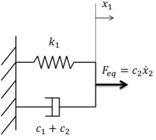
In Fig. 1, the parallel spring k1 and dashpot c1 elements represent the recoverable time dependent
viscoelastic behaviour whereas the dashpot c2 represents the irrecoverable viscoplastic response.
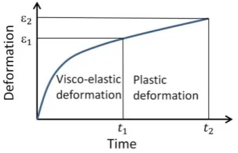
The typical behaviour of a rheological material specimen during a tensile test is presented in Fig. 2, where the phases of the viscoelastic and purely plastic (viscous) response are evidenced.
[image:5.595.193.366.572.683.2]The mathematical model of the force profile over time F(t) necessary to pull a specimen modeled with a three-element unit with a constant deformation velocity will be derived here below. This equation will be used in Section 3.4 in order to identify the material parameters (c1, k1, c2).
From the dynamic equilibrium of the system presented in Fig. 1 driven by a constant deformation velocity (𝑥̇2), it yields:
𝑚𝑥̈1 = −𝑘1𝑥1− 𝑐1𝑥̇1+ 𝑐2(𝑥̇2− 𝑥̇1) (1)
where m is the mass of the rheological material, and 𝑥1, 𝑥̇1, 𝑥̈1 are the position, velocity, and
acceleration of the point A in Fig. 1.
Neglecting the mass of the material with respect to the other components, and reordering the equation, it yields:
−𝑘1𝑥1− 𝑥̇1(𝑐1+ 𝑐2) +
𝐹
𝑒𝑞≅ 0 (2) [image:6.595.220.378.366.508.2]where 𝐹𝑒𝑞 = 𝑐2𝑥̇2 can be interpreted as the equivalent force to be applied to the equivalent system of
Fig. 3 in order to have the same deformation profile over time 𝑥1(𝑡) of the system in Fig. 1.
Fig. 3. Dynamic system equivalent to a three-element model driven by a constant deformation velocity.
The system in Fig. 3 is a simple first-order dynamic system, so that:
𝑥1(𝑡) =
𝐹
𝑘𝑒𝑞1 (1 − 𝑒 −( 𝑘1
𝑐1+𝑐2)𝑡) =𝑐2𝑥̇2 𝑘1 (1 − 𝑒
−( 𝑘1
𝑐1+𝑐2)𝑡) (3)
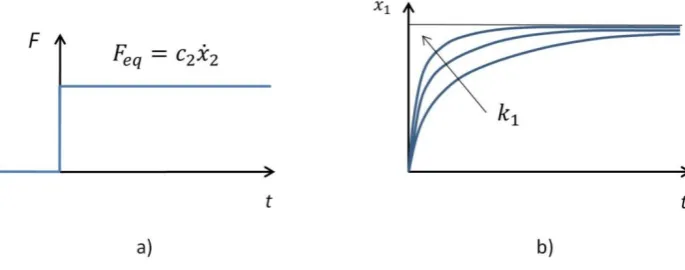
when the specimen is loaded with a step force profile, such as presented in Fig. 4.
As depicted in Fig. 4 b), after a transient period the system tends asymptotically to an equilibrium position (𝑥𝑒𝑞). As evidenced in the figure, if 𝑘1 is increased the transient is shorter (𝑥𝑒𝑞 is reached
beforehand), and the converse if 𝑘1 is decreased. The same effect (shorter transient and 𝑥𝑒𝑞 reached
beforehand) can be obtained if 𝑐1 (or 𝑐2) is decreased, and the converse if 𝑐1 (or 𝑐2) is increased. It is
worth noticing that if 𝑐2 is modified, also the value of 𝑥𝑒𝑞 =𝑐2𝑘𝑥̇2
1 changes accordingly.
Fig. 4. Step force profile (a)) and deformation response for increasing 𝑘1 (b)).
𝑥̇1(𝑡) =
𝑐2𝑥̇2 𝑐1+ 𝑐2∗ 𝑒
−( 𝑘1
𝑐1+𝑐2)𝑡 (4)
and, finally, the expression of F(t) is:
𝐹(𝑡) = 𝑘1𝑥1+ 𝑐1𝑥̇1= 𝑐2𝑥̇2(1 − 𝑒−( 𝑘𝑐1+𝑐12)𝑡) +
𝑐
1∗ 𝑐2𝑥̇2 𝑐1+ 𝑐2∗ 𝑒−( 𝑘1
𝑐1+𝑐2)𝑡 =
= 𝑐2𝑥̇2(1 − 𝑐2 𝑐1+ 𝑐2∗ 𝑒
−( 𝑘1
𝑐1+𝑐2)𝑡)
(5)
3. Experimental identification of material properties
3.1. Experimental setup
[image:7.595.185.411.581.732.2]In Fig. 5 the experimental setup for the tensile test of a thin rheological material (fondant icing) is presented. An Instron 3342 tensile test machine equipped with a high sensitivity load cell (Instron 2519-101) have been used. As shown in Fig. 5, an additional frame with horizontal test plane has been added, in order to perform tests with the specimen sliding on the horizontal plane (which sustains the specimen weight), thus avoiding the undesired deformations due to the specimen weight that would occur with the specimen in a vertical position.
a) b)
c) d)
e) f)
[image:8.595.73.523.90.709.2]g)
The specimen is fixed on one side (left side in Fig. 5) to the frame, and is pulled by means of an inextensible cable on the other side, which is connected to the machine sliding head thanks to a pulley that redirects the cable (and the load) along the vertical direction. The friction between the specimen and the test bench can be considered negligible.
3.2. Specimen construction
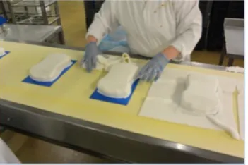
In the confectionery industry, fondant icing is produced in sheets with constant thickness (4*10-3 [m] in this study) which are manually shaped over cakes by skilled human operators in order to cover them.
The fondant icing sheets are separated by a polymeric film, which prevents the sheets to be bonded together. In fact, the material is very soft and sticky (similar to fresh wheat dough), and is easily plastically deformed when handled (due to its viscous behaviour). Therefore, the polymeric film is also useful for handling the fondant icing sheet without deforming it permanently. On the other hand, the fondant icing sheet has negligible flexural stiffness, similarly to a thin sheet of fresh wheat dough.
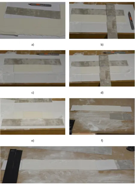
The procedure to produce a 0.2 [m] x 0.05 [m] specimen, with a thickness of 4*10-3 [m], is presented in Fig. 6.
First, a 0.3 [m] x 0.05 [m] piece of fondant icing and supporting polymeric film are cut (Fig. 6 a)) by using a calibrated mask and a cutter. Then, a 0.05 [m] x 0.05 [m] piece of fondant icing is removed from both sides of the specimen using the cutter and the mask as sliding guide (Fig. 6 b)), without cutting the polymeric film (which dimensions remain 0.3 [m] x 0.05 [m] at this stage). These uncovered polymeric film pieces are used as interface to fix the specimen to the test bench on one side, and to the horizontally sliding interface to the machine (0.1 [m] x 0.05 [m] rigid polymeric strip, see Figs. 6 f) and g)), which is attached to the cable connected to the vertically sliding machine head, on the other side (see Fig. 5). The specimen with both ends ready to be interfaced to the machine is presented in Fig. 6 c).
Then, a 0.1 [m] x 0.05 [m] strip of polymeric film is removed from the middle of the specimen, so that the corresponding part of the specimen (that is the part of the specimen which is stretched during the tensile tests) has a cross section of 0.05 [m] x 4*10-3 [m] of fondant icing only (without any polymeric film support). During the tensile tests, the fondant icing remains bonded to the supporting polymeric film, which is the interface with the testing machine, thanks to the stickiness of the material. The above mentioned removal operation, which is made with the specimen upside down using the cutter and the mask as sliding guide, is presented in Fig. 6 d), and the final specimen (upside down) is presented in Fig. 6 e). The rigid mask is then used to support the specimen while it is turned on the right side (upside up, as presented in Fig. 6 f)).
Finally, the specimen is fixed with a biadhesive tape to the horizontally moving machine interface (hard polymeric strip) on one side and with two strips of high strength tape to the test bench on the other side.
3.3. Tensile test results
Fig. 7. Tensile test curves for ten different fondant icing specimens.
Fig. 8. Average tensile test curve overlapped with the force profile obtained using the identified material parameters.
in the real industrial production. The experimental force profiles are reported in Fig. 7. In Fig. 8, the average tensile test curve is presented, which has been overlapped with the curve F(t) (Eq. (5)) obtained using the material parameters that have been identified in Section 3.4. The average break force (crack initiation, see Fig. 9 b)) of the tested specimens is 1.04 [N].
In Fig. 9 different phases of the tensile test of a fondant icing specimen are presented. In particular, the specimen positioned in the machine just before the start of the tensile test is depicted in Fig. 9 a). In Fig. 9 b) the initiation of a crack in the specimen is reported. The crack propagation phase is depicted in Fig. 9 c) and, finally, in Fig. 9 d) the specimen completely broken (two separated pieces) is presented.
3.4. Identification method
In this Section, the three-step method used for the identification of the rheological material properties is presented, which uses the experimental data from the tensile tests presented in the previous Section. In particular, the average tensile test curve (see Fig 8) is used, and the material parameters to be determined using the experimental data are c1, k1, c2 (see Fig. 1). This method has been used to
[image:10.595.184.410.270.427.2]a) (t = 0 [s])
b) (t = 39 [s])
c) (t = 41 [s])
[image:11.595.182.411.64.552.2]d) (t = 49 [s])
Fig. 9. Phases of fondant icing tensile test.
3.4.1. Step 1 – Dashpot c2 constant determination
The dashpot 𝑐2 constant, which is related to the purely plastic behaviour of the material, can be
determined through the asymptotic behaviour of the material. Two alternative methods are presented here, but only the second one can be used in the case of fondant icing, as it is explained below.
The first method is based on Eq. (5), which for t → ∞ (or sufficiently high) becomes:
𝐹𝑚𝑎𝑥 = 𝑐2𝑥̇2 (6)
where 𝐹𝑚𝑎𝑥 is the maximum value of 𝐹(𝑡) (i.e., the asymptotic value), which makes it immediate to
icing because the material starts to break significantly before that the asymptotic value of 𝐹(𝑡) is reached (see Fig. 8). Anyway, the presented method can be used in the case of other rheological materials that can be modeled with a three-element system and do not present this problem.
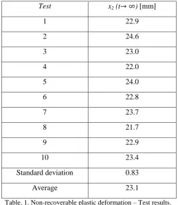
In the second proposed method, the value of the non-recoverable plastic deformation when the specimen is loaded with a constant force 𝐹 for a time 𝑡1 (see Fig. 10) is used as input for the
[image:12.595.147.446.184.352.2]determination of 𝑐2. The average value from the test of ten specimens is used.
Fig. 10. Total deformation of a specimen of fondant icing loaded with a constant force F for a time t1 (phase 1)
and recovery of the viscoelastic deformation (phase 2).
If the three-element model of Fig. 1 is loaded with a constant force 𝐹, such as in the phase 1 of Fig. 10, the total deformation is:
𝑥2(𝑡) = 𝑥2,1(𝑡) + 𝑥2,2(𝑡) (7)
with:
𝑥2,1(𝑡) =𝐹𝑡𝑐
2
𝑥2,2(𝑡) = 𝐹
𝑘1(1 − 𝑒
−(𝑘𝑐1
1)𝑡)
(8)
where 𝑥2,1(𝑡) is related to the non-recoverable plastic deformation of the dashpot element 𝑐2, and
𝑥2,2(𝑡) is related to the recoverable viscoelastic deformation (elements 𝑘1 and 𝑐1), which will be
(asymptotically) completely recovered in the phase 2 of Fig. 10 after that the force is removed from the system. These two terms are easily understood, since 𝑥2,1(𝑡) is the response of a first-order
dynamic system formed by one dashpot (element 1), which is loaded with a step force 𝐹, and 𝑥2,2(𝑡)
is the response of a first-order dynamic system formed by a dashpot and a spring in parallel (element 2) loaded with the same step force 𝐹. In fact, element 1 and element 2 are connected in series (see Fig. 1) and, therefore, they are loaded by the same force.
After that the force 𝐹 has been removed the viscoelastic deformation is asymptotically recovered (𝑥2,2(𝑡 → ∞)→ 0) and, therefore, the total deformation is equal to the non-recoverable plastic
deformation. The latter in turn is equal to the non-recoverable plastic deformation generated during phase 1 only (i.e., from 𝑡 = 0 to 𝑡 = 𝑡1, which is the time in which 𝐹 is switched to zero), because
𝑥2(𝑡 → ∞) = 𝑥2,1(𝑡 → ∞) = 𝑥2,1(𝑡 = 𝑡1) (9)
Therefore, from Eqs. (8) and (9):
𝑐2 = 𝐹𝑡1 𝑥2,1(𝑡 = 𝑡1)=
𝐹𝑡1
𝑥2,1(𝑡 → ∞)=
𝐹𝑡1
𝑥2(𝑡
→ ∞
) (10)where 𝑥2(𝑡 → ∞) is the non-recoverable plastic deformation.
In Table 1, the non-recoverable plastic deformation measured in the ten tests performed and the related average value are presented. The tests have been performed applying a constant force 𝐹 = 0.5 [N] for a time 𝑡1 = 60 [s] to the fondant icing specimens using the experimental setup of Sections 3.1 and measuring the non-recoverable plastic deformation with a calibrated vision system. By
substituting the average value of 𝑥2(𝑡 → ∞) and the values of 𝐹 and 𝑡1 in Eq. (10), the value of the
dashpot constant 𝑐2 = 1.30*103 [Ns/m] is obtained.
Test x2 (t→ ∞) [mm]
1 22.9
2 24.6
3 23.0
4 22.0
5 24.0
6 22.8
7 23.7
8 21.7
9 22.9
10 23.4
Standard deviation 0.83
[image:13.595.169.429.309.607.2]Average 23.1
Table. 1. Non-recoverable plastic deformation – Test results.
3.4.2. Step 2 – Dashpot c1 constant determination
From Eq. (5), the value of the force at the beginning of a tensile test is:
𝐹(𝑡 = 0) = 𝑐2𝑥̇2(1 − 𝑐2
𝑐1+ 𝑐2) (11)
The experimental tensile tests clearly indicate that 𝐹(𝑡 = 0) = 0 (see Figs. 7 and 8). Therefore, from Eq. (11), it can be noticed that 𝑐1 can be approximated to zero, since both 𝑐2 and 𝑥̇2 are not null. It can
be approximated with a Maxwell model, which is composed by a spring and a dashpot element connected in series.
3.4.3. Step 3 – Spring k1 stiffness determination
Once that 𝑐1 and 𝑐2 have been identified in the previous steps, the spring stiffness 𝑘1 can be determined by using linear least squares interpolation. For this purpose Eq. (5) can be rearranged in the form:
𝑌 + 𝑏𝑋 = 0 (12)
where:
𝑌 = ln (1 − 𝐹
𝑐2𝑥̇2) + ln (
𝑐1+ 𝑐2 𝑐2 )
𝑋 = 𝑡 𝑏 = 𝑘1
𝑐1+ 𝑐2
(13)
All pairs of corresponding values (𝐹, 𝑡) of the average experimental curve (see Fig. 8) are used as input for the interpolation (discarding all points after the break of material).
The value of 𝑏 which minimizes the errors in a least square sense between the interpolated curve and the experimental points is 𝑏 = 73.1*10-3 [1/s] and, therefore, the least squares estimate of the spring stiffness is 𝑘1 = 95.0 [N/m].
The effectiveness of the proposed identification method is demonstrated by the fact that the curve of
𝐹(𝑡) using the material parameters identified with the proposed method has a good fit with the average experimental curve (before crack initiation), as presented in Fig. 8. It can be also concluded that the good fit with the experimental results validates the choice of the three-element material model.
4. Rheological object dynamic model and validation
4.1. Dynamic model
[image:14.595.211.387.582.699.2]In the production of celebration cakes, the fondant icing sheets are placed over cakes and then
Fig. 11. Manual shaping of fondant icing over a celebration cake.
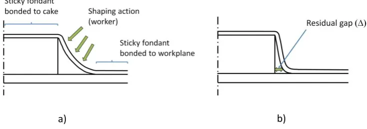
packaging. A cross section of a cake covered with fondant icing before the shaping operation (a)) and the same cake after the shaping (b)) are presented in Fig. 12.
[image:15.595.101.469.117.247.2]a) b)
Fig. 12. Cross section of a celebration cake before (a)) and after the shaping (b)).
In this Section, the multibody dynamic model developed for simulating the 2-D shaping of fondant icing over celebration cakes is presented. The simulation software ADAMS (MSC Software) is employed to model and compute the dynamic motion of the system. The model and the method used for validation (see Sections 4.2 and 4.3) can be straightforwardly applied to the 2-D shaping of a generic thin rheological object.
A catenary-like MSD model formed of lumped masses interconnected with three-element units is proposed to simulate the 2-D shaping of fondant icing (thin rheological material) over a celebration cake (moulding object). The three-element units are connected to the masses by frictionless revolute joints. Internodal distances between masses and forces in unit elements change due to the action of external forces (forces generated by the shaping tool, reaction forces from the moulding surface, and gravity force), and as a result rheological deformation occurs in each three-element unit and the shape of the catenary changes.
In order to simplify the analysis, the following assumptions have been made:
- the flexural stiffness of fondant icing is negligibly small (similarly to a thin sheet of fresh wheat dough);
- the friction between the fondant icing and both the shaping tool and moulding surface can be neglected (in the real industrial production, sugar powder is used in order to avoid undesired effects due to the stickiness of the material and reduce friction);
- the proposed 2-D model can be applied to rectangular cross-section and also to cylindrical cakes, since it is assumed that the effect of circumferential stresses on the shaping operation can be neglected, and the approximation is more reasonable for cakes with large diameter;
- thanks to its stickiness, the fondant icing can be considered (with good approximation) bonded to the top of the cake and to the workplane (see Fig. 12 a));
- the change in thickness of the fondant icing during the shaping operation can be neglected.
All these assumptions and the proposed dynamic model for the system have been verified through experimental validation (see Sections 4.2 and 4.3).
1. Possible generation of cracks in the proximity of the top edge of the cake (as also noticed in the industrial production) due to an excessive force or deformation velocity applied by the human operator, which generate high stresses in the material, and the weight of all the catenary.
2. After the shaping process a residual gap (, see Fig. 12 b)) exists between the cake and the fondant icing in proximity of the bottom of the cake. This displacement is directly related to the quality of cakes (and their acceptance) and, for example, considering a diameter of 0.18 [m] (as in this study), cakes with m] will not pass the quality control check and need to be reprocessed or discarded.
The lumped parameters model developed in ADAMS with the above assumptions is presented in Fig. 13 a). In particular, in Fig. 13 a) the catenary configuration approximates the real one when the fondant icing is positioned over a cake before the shaping operation.
[image:16.595.73.520.262.426.2]a) b) c)
Fig. 13. Fondant icing multibody model: a) undeformed model (t = 0 [s]), b) deformation due to gravity force (t = 1.0 [s]), c) comparison between simulated and experimental deformation.
The lumped masses have been modeled using rigid spheres with diameter equal to the thickness of the fondant icing (4*10-3 [m]). Their mass has been experimentally determined by weighting a strip of fondant icing, and scaling the value according to the number of lumped masses per unit length in the model. In particular, considering a strip of material with the same width of the specimens used for material identification (Section 3), the mass of each sphere is m = 2*10-3 [kg].
A frictionless contact (rigid bodies cannot interpenetrate) has been implemented in the multibody model between the spheres and the shaping tool, and between the spheres and the moulding surface. In this way it is possible to simulate the dynamic behaviour of the fondant icing that is forced to deform over the moulding surface by the shaping tool.
Two test cases have been chosen for the experimental validation of the proposed dynamic model:
- Test case 1: fondant icing deformed under the effect of its weight;
- Test case 2: fondant icing shaped over the cake with a vertical movement of the shaping tool.
In both test cases the catenary computed in the dynamic simulation is compared with the corresponding experimental one, which is measured with a calibrated vision system.
55 [
m
m
]
1) 2) 3) 4)
Movement 1
1)
2) 3) 4)
Movement 2
1) 2) 3) 4)
Movement 3
1) 2) 3) 4) 5)
[image:17.595.72.529.66.629.2]Movement 4
Fig. 14. Shaping sequences for different movements of the tool.
4.2. Experimental validation - Test case 1
4.3. Experimental validation - Test case 2
In this test case the simulated and experimental fondant icing profiles are compared after the shaping operation, which has been performed with a vertical movement of the shaping tool (see movement 1 in Fig. 14). The shaping tool is moved down (and then up to the initial position, after the shaping) with a speed of 1*10-3 [m/s], and then it is stopped on the cake (at the end of travel of the tool, and with the maximum stretch of the fondant, see phase 3) in the figure) for 30 [s] in order to shape it properly. This stop, which is also necessary in the real industrial production, is aimed at relaxing the internal tensions in the fondant icing thus producing the required plastic deformation.
As it can be noticed in Fig. 14, the number of lumped masses (spheres) in the model has been chosen in order to have at least three spheres in contact with the tool during the shaping phase. In this way, the internal tensile force along the catenary is almost constant (except for small deviations due to the material weight) and, moreover, it has a smooth profile during the shaping process.
[image:18.595.218.380.333.462.2]The fondant icing experimental and simulated profiles are compared in Fig. 15, and the maximum error between the two with respect to the fondant icing undeformed configuration (Fig. 13 a)) is less than 3.0 %.
Fig. 15. Comparison between simulated and experimental profile of fondant icing after the shaping operation.
Since in both test cases the error is less than 6.5%, the dynamic model is experimentally validated with a good approximation and, therefore, it can be used to simulate other different movements of the shaping tool, e.g. the movements presented in Fig. 14, which are discussed in Section 5.
5. Comparison of different shaping procedures
After that the fondant icing dynamic model has been experimentally validated, in this Section different solutions for the fondant shaping have been compared in order to find the most suitable shaping procedure.
In particular, four different movements have been analyzed and compared (using the same shaping tool), taking in particular consideration the following parameters:
- maximum tensile force in the material, which has to be sufficiently far from the break of the material (Fbreak = 1.04 [N], see Section 3.3).
of view if the residual gap after the shaping process (defined in Fig. 12 b)) between the cake and the fondant icing in proximity of the bottom of the cake is m], otherwise it needs to be reprocessed or discarded.
The four shaping movements considered and compared in this study are presented in Fig. 14. In each of them, the same tool deforms the fondant icing approaching it from a different direction. In
movements 1-3, the approach direction is vertical, horizontal, and inclined by 45 [deg] with respect to the horizontal, respectively. Movement 4 (2-step shaping) is formed by a vertical and then by a horizontal movement. In all the considered cases, the tool velocity is 10-3 [m/s] which is compatible with the required production speed and with the fondant icing deformation velocity in the current production. A processing time of 120 [s] is considered which is related to a reasonable productivity in the industrial production.
Each of these movements can be divided into four phases, as depicted in Fig. 14:
1) Phase 1 – Tool approach: the tool approaches the fondant icing (from different directions) which is deformed like a catenary under the effect of its weight. A small plastic deformation occurs in this phase due to the weight of the material.
2) Phase 2 – Forced elasto-plastic deformation: the tool forces the fondant icing to stretch up to the end of travel of the tool in each direction and, therefore, both the springs and dashpots in the model are stretched.
On one side, the dashpot deformation is plastic and non-recoverable and, on the other side, the elastic deformation generates an internal tensile force in the fondant icing that will continue to plastically deform the dashpot elements in the following phase (phase 3).
The tensile force generated in the catenary of fondant icing by the tool action is almost constant in all the material elements, except for the effect of the weight of the spheres (which makes the top element (element 1) slightly more stressed). Indeed, at least three spheres are in contact with the tool during the shaping, and therefore – thanks also to the frictionless contact tool-spheres – the tool is able to change the direction of the tensile force in the catenary without affecting its module.
3) Phase 3 – Internal tensile force relaxation: in this phase, the shaping tool is stopped at the end of its travel (corresponding to the maximum stretch of the fondant icing) for 30 [s] and, thanks to the internal tensile force generated in the springs in phase 2, the dashpot elements are stretched further, increasing their plastic non-recoverable deformation. In the meantime, the springs reduce their length and their internal force is gradually relaxed (thus reducing the elastic energy stored).
4) Phase 4 – Elastic recovery and settlement on the final shape: in this phase, the shaping tool
detaches from the fondant icing and returns to its home position. As soon as the tool detaches from the fondant icing, the springs are no more forced to stay in a stretched and stressed configuration and, therefore, a quick recovery of their elastic deformation occurs (with a corresponding reduction of the tensile force in the fondant icing). After the recovery of the springs elastic deformation, the fondant icing continues to plastically deform very slowly under the effect of its weight.
Phases 2 and 3 are the most important ones, since most of the plastic deformation occurs in these two phases thanks to the tensile force generated in the fondant icing with the action of the shaping tool.
14), and then it stops at the end of travel of the second (horizontal) movement for other 15 [s] (phase 4) of movement 4 in Fig. 14). In total, a 30 [s] stop is used for comparison purposes, similarly to movements 1-3.
The main results of the dynamic simulations related to movements 1-3 are presented in Fig. 16. In particular, in Fig. 16 a) (top) the tensile force in the material (for the more stressed element, i.e. for element 1) and the total deformation of the fondant icing are presented for the four different phases, and in Fig. 16 a) (bottom) the deformations of the spring and dashpot of element 1 are presented, which help to understand how the total deformation is obtained summing the elastic and plastic
a)
b)
[image:20.595.119.482.223.746.2]
c)
Fig. 16. Internal tensile force and deformation of fondant icing using movement 1 (a)), 2 (b)), and 3 (c)).
deformation contributions. The behaviour of element 1 can be considered representative of the behaviour of all the elements in the fondant icing model since the internal tensile force and the related deformations are almost the same in all elements.
From the analysis of Fig. 16 a), it can be noticed that most of the total deformation (see top of figure), which is composed by elastic and plastic deformations (in the springs and dashpots, respectively, see bottom of figure), is obtained in phase 2 when the tool is actively forcing the deformation, whereas in phase 3 the total deformation is almost constant (top of figure). Analyzing in more detail what happens in phase 3, the total deformation is constant, but is composed by an elastic deformation component which is decreasing and by a plastic deformation component which is increasing (see bottom of figure): the elastic deformation is decreasing and generates plastic deformation (internal elastic tensions are relaxing). The maximum tensile force can be found at the end of phase 2, because when the tool stops, the relaxation of tensions starts (with conversion of elastic energy into plastic deformation). Then, at the beginning of phase 4 a small elastic return can be noticed (the total deformation and the spring 1 deformation decrease, see Fig. 16 a)) which is due to the release of the elastic energy in the system that has not been completely converted in plastic deformation in the previous phases.
If the tool was retracted immediately after phase 2, a much bigger elastic return would have occurred, with the result of a significantly lower plastic deformation and, therefore, a not acceptable cake quality.
Similar considerations can be drawn for movements 2 and 3 (Fig. 16 b) and c)), with different values of maximum tensile force and total deformation.
The main results from the simulation of movement 4 are presented in Fig. 17. In this case, the phase in which the tool actively stretches the fondant icing is divided in two parts: 1. The shaping tool moves vertically up to the vertical end of travel (see phase 3) of movement 4 in Fig. 14); 2. The shaping tool moves horizontally up to the horizontal end of travel (see phase 4) of movement 4 in Fig. 14). The two corresponding peaks of force are depicted in Fig. 17 (top). These two forced deformation phases are separated by a tension relaxation phase of 15 [s], in which the total deformation is almost constant, see top of figure, and part of the elastic energy is converted into plastic deformation. This allows the peak tensile force to be reduced, since an already plastically deformed fondant icing is
[image:21.595.113.475.545.743.2]
stretched in the second forced deformation phase. A second tension relaxation phase of 15 [s] follows, after the horizontal tool movement up to its end of travel.
[image:22.595.85.524.178.347.2]Concerning the simulation of movement 4, by varying the distance d of the tool from the cake, the maximum tensile force changes and has a minimum for d = 14.5*10-3 [m] (see Fig. 18), for which the force peaks are equal, which is the case represented in Fig. 17. This distance corresponds to the optimal duration ratio between the two (horizontal and vertical) movements.
Fig. 18. Maximum tensile force for different distances of the tool from the cake (movement 4).
In Table 2 the four proposed movements are compared in terms of maximum tensile force (Fmax,
which has to be less than Fbreak = 1.04 [N]) and residual gap (which has to be less than 5*10 -3
[m] for an acceptable cake quality).
Fmax[N] SF [m]
Movement 1 0.845 1.23 2.67*10-3
Movement 2 0.837 1.24 3.01*10-3
Movement 3 1.005 1.03 3.08*10-3
Movement 4 0.658 1.58 4.00*10-3
Table. 2. Maximum tensile force, Safety Factor, and residual gap – Movements 1-4.
Movements 1 and 2 have quite similar Fmax and (see also the similar force and deformation profiles
in Fig. 16 a) and b)), whereas movement 3 has an higher Fmax due to a shorter path of the tool during
phase 2 with respect to movements 1 and 2, which corresponds to a higher deformation velocity of the fondant icing.
From the analysis of Table 2, it can be concluded that movement 4 is the one that has a minimum Fmax
and, therefore, can assure a safer shaping with respect to the other movements, and in the meantime has an acceptable value of . In particular, movement 4 has a significantly higher Safety Factor (SF = 1.52), defined as SF = Fmax/Fbreak, with respect to the other movements.
A higher shaping tool speed would be beneficial concerning the speed of generation of the plastic non-recoverable deformation (since it would generate a higher tensile force in the fondant icing and, therefore, a higher plastic deformation velocity), but on the other side it is not feasible because the
[image:22.595.67.530.434.547.2]higher tensile force would increase the risk of breaking the material during the production (thus generating scraps).
On the other side, a lower shaping tool speed could be beneficial in reducing Fmax, but in this case
would be higher, resulting in a not acceptable cake quality. For example, in Fig. 19 the result of a simulation for movement 1 with a tool velocity of 0.5*10-3 [m/s] (half of the velocity used in the previous simulations) and a phase 2 of 60 [s] is presented. In this simulation there is no phase 3 (forced deformation with stationary tool), so that the total forced deformation time (phase 2 plus phase 3) is 60 [s] as in the previous case (movement 1) for comparison purposes.
[image:23.595.117.479.212.414.2]
Fig. 19. Internal tensile force and deformation of fondant icing using movement 1 with a tool velocity of 0.5*10-3 [m/s].
From the analysis of Fig. 19 it can be noticed that Fmax is reduced; nevertheless, = 6.6*10-3 [m] and,
therefore, the cake would not pass the quality control check. The same considerations also apply to movements 2 and 3.
Therefore, it can be concluded that a reduced tool speed leads to a beneficial reduction of Fmax, but in
this case an excessive is present, which implies a not acceptable cake.
a) b) c)
Fig. 20. Robotic cell with two shaping stations installed at Lightbody of Hamilton - Finsbury Food Group (a)), shaping tool over the cake before shaping (b)), and fondant icing over the cake after shaping (c)).
In Fig. 20 a), a picture of the robotic cell developed during the project mentioned in the
[image:23.595.81.508.555.674.2]operation is presented in Fig. 20 b). The shaping tool in Fig. 20 b) has the same cross section of the shaping tool considered in this paper (see for example Fig. 14). The final result of the shaping
operation is presented in Fig. 20 c). The quality of the shaping operation was very good, with an error with respect to the desired shape well within the specified tolerance, such as predicted by simulation.
6. Conclusions
In this paper, a catenary-like MSD model formed of lumped masses interconnected with three-element units is proposed to study and simulate the 2-D shaping of a thin rheological material over a moulding object. A three-step method for identifying the material properties from tensile tests of several thin specimens is presented, which has allowed both to identify the material properties and to validate the three-element material model used. For the particular rheological material tested (fondant icing), it has been found by experimental evidence that the first dashpot constant can be approximated to zero and, therefore, the material model can be approximated with a Maxwell model. A multibody model of the rheological object and of the shaping operation is then proposed, which has been validated thanks to the close agreement between the simulated deformation profiles and the
experimental ones. Finally, different shaping procedures and velocities of the shaping tool have been compared by dynamic simulations, with particular attention to the internal tensile force generated in the material and the aesthetic quality of the product, measured by the distance of the deformed material profile with respect to the desired shape. A two-step shaping movement resulted more advantageous with respect to simpler motions since significantly reduced internal forces are generated in the material while the aesthetic quality of the shaped object is still guaranteed. Regarding the effect of the shaping tool velocity, a higher tool speed is beneficial concerning the speed of generation of the plastic non-recoverable deformation, but the risk of breaking the material during the production is increased. On the other side, a lower tool speed is beneficial in reducing the maximum tensile force in the material, but in this case the residual gap is higher, which implies a not acceptable cake quality. The 2-step shaping procedure has been implemented in a robotic cell in industrial environment, and the quality of the shaping operation was very good, with an error with respect to the desired shape well within the specified tolerance, such as predicted by simulation. The methods presented in this paper can be straightforwardly applied to the robotic shaping of a thin film of a generic rheological material (e.g., dough-like materials, such as wheat dough, shortcut pastry, marzipan, etc.) which can be modeled with a three-element system, for example for the production of salt or sweet pies, or complex shape stuffed pasta, and in general in the confectionery and bakery industry.
Acknowledgement
This research was supported in part by EPSRC under the project “A Smart and Flexible Automation System for High Value Cake Manufacturing” (Grant No. EP/L505213/1). No additional research data from this project can be published due to a non-disclosure agreement with the company Lightbody of Hamilton part of the Finsbury Food Group.
References
[2] V. Mallapragada, N. Sarkar, and T. Podder, “Toward a robot-assisted breast intervention system,” IEEE/ASME Trans. Mechatronics, vol. 16, no. 6, pp. 1011-1020, 2011.
[3] M. Saha and P. Isto, “Manipulation planning for deformable linear objects,” IEEE Trans. Robot., vol. 23, no. 6, pp. 1141-1150, 2007.
[4] E. Park and J. Mills, “Static shape and vibration control of flexible payloads with applications to robotic assembly,” IEEE/ASME Transactions on Mechatronics, vol.10, no. 6, pp. 675-687, 2005.
[5] D. Navarro-Alarcon, Y.-H. Liu, J.G. Romero, P. Li, “On the visual deformation servoing of compliant objects: Uncalibrated control methods and experiments,” International Journal of Robotics Research, vol. 33, no. 11, pp. 1462-1480, 2014.
[6] D. Navarro-Alarcon, H.M. Yip, Z. Wang, Y.-H. Liu, F. Zhong, T. Zhang, P. Li, “Automatic 3-D
Manipulation of Soft Objects by Robotic Arms with an Adaptive Deformation Model,” IEEE Transactions on Robotics, vol. 32, no. 2, pp. 429-441, 2016.
[7] D. Navarro-Alarcón, Y.-H. Liu, J.G. Romero, P. Li, “Model-free visually servoed deformation control of elastic objects by robot manipulators,” IEEE Transactions on Robotics, vol. 29, no. 6, pp. 1457-1468, 2013. [8] J.F. Steffe, “Rheological Methods in Food Process Engineering,” second ed., Freeman Press, East Lansing, 1996 (Chapter 5).
[9] S. Tokumoto, Y. Fujita, S. Hirai, “Deformation modeling of viscoelastic objects for their shape control,” in Proc. IEEE International Conference on Robotics and Automation, vol. 1, pp. 767-772, 1999.
[10] Z. Wang, S. Hirai, “Modeling and estimation of rheological properties of food products for manufacturing simulations,” Journal of Food Engineering, vol. 102, no. 2, pp. 136-144, 2011.
[11] M. Kimura, Y. Sugiyama, S. Tomokuni, S. Hirai, “Constructing rheologically deformable virtual objects,” in Proc. IEEE International Conference on Robotics and Automation, vol. 3, pp. 3737-3743, 2003.
[12] J. Das, N. Sarkar, “Robust shape control of deformable objects using model-based techniques,” Advanced Robotics, vol. 25, no. 16, pp. 2099-2123, 2011.
[13] T. Ikawa, H. Noborio, “On the precision and efficiency of hierarchical rheology MSD Model,” in Proc. IEEE International Conference on Intelligent Robots and Systems, pp. 376-383, 2007.
[14] R. Nogami, H. Noborio, F. Ujibe, H. Fujii, “Precise deformation of rheologic object under MSD models with many voxels and calibrating parameters,” in Proc.IEEE International Conference on Robotics and Automation, vol. 2, pp. 1919-1926, 2004.
[15] H. Noborio, R. Enoki, S. Nishimoto, T. Tanemura, “On the calibration of deformation model of rheology object by a modified randomized algorithm,” in Proc. IEEE International Conference on Robotics and Automation, vol. 3, pp. 3729-3736, 2003.
[16] H. Noborio, R. Nogami, R. Enoki, “Precise deformation of rheology MSD model calibrated by randomized algorithm,” Eurographics 2003, pp. 171-178, 2003.
[17] S. Tokumoto, S. Hirai, H. Tanaka, “Constructing Virtual Rheological Objects,” in Proc. World Multiconference on Systemics, Cybernetics and Infomatics, pp.106-111, Orlando, 2001.
[18] Z. Wang, S. Hirai, “Modeling and Parameter Estimation of Rheological Objects for Simultaneous Reproduction of Force and Deformation,” in Proc. 1st International Conference on Applied Bionics and Biomechanics, Venice, 2010.
[20] Z. Wang, K. Namima, S. Hirai, “Physical parameter identification of rheological object based on
measurement of deformation and force,” in Proc. IEEE International Conference on Robotics and Automation, pp. 1238-1243, 2009.
[21] B.S. Evans, P.N. Brett, “Computer simulation of the deformation of dough-like materials in a parallel plate gripper,” Proceedings of the Institution of Mechanical Engineers, Part B: Journal of Engineering Manufacture, vol. 210, no. 2, pp. 119-126, 1996.
[22] N. Sakamoto, M. Higashimori, T. Tsuji, M. Kaneko, “An optimum design of robotic food handling by using Burger model,” Intelligent Service Robotics, vol. 2, no. 1, pp. 53-60, 2009.
[23] N. Ueda, S. Hirai, H.T. Tanaka, “Extracting rheological properties of deformable objects with haptic vision,” in Proc. IEEE International Conference on Robotics and Automation, vol. 4, pp. 3902-3907, 2004.
[24] R.S. Stone, P.N. Brett, B.S. Evans, “An automated handling system for soft compact shaped non-rigid products,” Mechatronics, vol. 8, no. 2, pp. 85-102, 1998.
[25] M. Higashimori, K. Yoshimoto, M. Kaneko, “Active shaping of an unknown rheological object based on deformation decomposition into elasticity and plasticity,” in Proc. IEEE International Conference on Robotics and Automation, pp. 5120-5126, 2010.
[26] T. Wada, S. Hirai, S. Kawamura, N. Kamiji, “Robust manipulation of deformable objects by a simple PID feedback,” in Proc. IEEE International Conference on Robotics and Automation, vol. 1, pp. 85-90, 2001.
[27] T. Inahara, M. Higashimori, K. Tadakuma, M. Kaneko, “Dynamic nonprehensile shaping of a thin rheological object,” in IEEE International Conference on Intelligent Robots and Systems, pp. 1392-1397, 2011.