Development of a high-power,
ultrashort pulse duration
optical parametric
amplification system
by
Hugo Giordano
June 1998
A thesis submitted for the degree of
Doctor of Philosophy
This thesis is entirely my own work, except where explicitly indicated.
iordano
Laser Physics Centre
Research School o f Physical Sciences and Engineering Australian National University
Acknowledgments
There are many people who have helped me along this very long, windy path towards completing my PhD. Without them I would never have found the way to the end.
I would like to thank my supervisors Prof. Barry Luther-Davies, Dr Andrei Rode and Prof. Eugene Gamaly. Barry was always there asking poignant questions which would send me scurrying away back to the lab or computer in search for an answer. More often than not finding that the answer was helpful to continuing my work. Thanks to Andrei who was always there to lend a hand with experiments and to complain too when things weren’t working. I would also like to thank Dr Yanjie Wang, who worked as a Post-Doctoral Fellow in the same lab when I first started, for his kind assistance and instruction.
Many people in the Centre deserve thanks because without their practical skills I would still be staring at an empty optical bench. Thanks to Ian McRae, Wally Hopkinson, Craig MacLeod and John Bottega for constructing and dealing with all things mechanical. It was great to go to the workshop with an idea of what I thought was needed and to leave with something that would actually work much better than my original idea. Thanks to Mike Pennington, Warren Baker and Paul Morrison who were always willing to make electronic devices, despite often having only vague ideas from me on what I wanted. Thanks to Anita Smith for her help. She had to put up with me and my PhD more than anyone else in the Centre for a quite a while.
To the Samocs, Neil Manson, Maryla and Wieslaw, Alex Boiko, John Martin, Robbie Charters, Changjiang Wei, Matt Sellars and everyone else, you were ever helpful in providing advice and information. Diane Hodges and Karen Montefiore were always there to be Oracles on whatever I needed to know or to do regarding the School or University or whatever.
To the crazy dudes who live in Greenacres and the surrounding PhD student environs, many thanks. Always a source of fun, information, friendship and stupid postcards; without you I would have gone completely insane many years ago. Thanks to Sleepy Max, Chief Administrator Esa, Bruce the Snake, Sex Rocket Subho, Smelly Phil, Double Dougster, Jason, David, Jen, Andrew, Kylie, Tim, Weijian, Andy G, Geoff, Wenqian, Scott and Max L.
Abstract
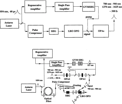
This thesis presents work carried out into the design and construction of an optical parametric amplification system to produce ~ GW power, sub-500 fs pulses that are wavelength tunable from 1.3 pm to 1.6 pm. Instead of using femtosecond lasers and amplifiers, such as those based on Ti:Sapphire, the system was based on the longer pulse duration Nd:YLF lasers and amplifiers. A cw, mode-locked Nd:YLF laser acted as the master oscillator to provide initial 60 ps pulses for use by a synchronously pumped optical parametric oscillator (OPO) and two optical parametric amplifiers (OPAs).
The OPO, based on Lithium Triborate (LBO), was pumped by the frequency doubled, compressed pulse from the Nd:YLF laser. Utilising a optical fibre-diffraction grating pulse compressor the pulses were compressed from 60 ps to ~ 2.5 ps in duration and the available peak power enhanced from 4.5 kW to 16 kW. After SHG the 527 nm pulses were 2.3 ps in duration and had peak powers of 6.5 kW. This was more than enough to drive the OPO up to six times above threshold with minimal cavity losses. With the addition of an intracavity dispersion compensating prism pair the OPO produced ~ 200 W, ~ 1.5 ps Gaussian pulses from 780 nm to 900 nm that displayed no discernible phase modulation. These pulses were planned to be used as seed pulses for OPAs.
The OPO displayed the novel behaviour of the resonated signal pulse oscillating on several widely spaced, multiple wavelengths and there were radical changes in the idler beam profile from a Gaussian-like beam into a ring shaped beam with small shifts in the cavity length. Both effects were linked to the ability to drive the OPO many times above threshold where the parametric gain was saturated and the internal conversion efficiency was maximised.
It was envisaged that a group velocity mismatched second harmonic generation (GVMSHG) system would produce high power, sub-500 fs, 527 nm pulses to amplify the seed signal pulses from the OPO in the OPAs. Nd:YLF regenerative and single pass amplifiers boosted the energy of frequency chirped pulses from the Nd:YLF laser to ~ 18 mJ while reducing the pulse duration to ~ 6 ps, through the narrow gain bandwidth of Nd:YLF, to provide the high power fundamental pulse. Using type II SHG in Potassium Dihydrogen Phosphate (KDP) a second harmonic (SH) pulse can be efficiently generated and compressed in time through careful use of the intrinsic group velocity mismatch (GVM) in KDP and by delaying the e- ray fundamental with respect to the o-ray fundamental before entering the KDP SHG crystal(s). Even under the non-optimal conditions in the experiment it was expected that a 2 mJ, sub-500 fs SH pulse would result from the GVMSHG system.
Significant problems became apparent during the experiments with the GVMSHG system that inhibited the GVM compression mechanism from performing efficiently. Considerable effort was out into fixing these problems; which were finally solved shortly before this thesis was due for submission. It is expected that future experiments will produce the expected SH pulses.
While experiments were not performed, numerical simulations were undertaken to optimise the design of the OPAs. Using a two crystal optical parametric amplification system it is expected that ~ 600 MW, ~ 300 fs signal pulses, tunable from 780 nm to 900 nm, and -300 MW, — 300 fs idler pulses, tunable from 1270 nm to 1625 nm, will be produced by the seed signal pulses from the OPO when pumped by the compressed SH pulse from the GVMSHG system.
Contents
1. IN T R O D U C TIO N ...1
1.1 Opticalparametricprocesses... 1
1.2 Overview... 2
1.3 Briefreviewofpreviousw or k...5
1.3.1 Pulse compressors...5
1.3.2 Optical parametric oscillators...6
1.3.3 Group velocity mismatched second harmonic generation...6
1.3.4 Optical parametric amplifiers... 7
1.4 Thesisoutline...7
1.5 References... 8
2. THE OPO PUMP LASER SYSTEM ...12
2.1 Introduction... 12
2.2 The Nd:YLF laser... 14
2.3 Thepulsecompressor... 15
2.3.1 Theory...16
2.3.1.1 Self-phase modulation...16
2.3.1.2 Stimulated Raman scattering... 18
2.3.1.3 Grating compressors... 20
2.3.2 Predicted Compressor Performance... 22
2.3.2.1 Polarisation control... 22
2.3.3 Experimental performance...23
2.3.3.1 Measurements...25
2.4 Thesecondharmonicgenerator... 30
2.5 Sum m ary... 35
2.6 References... 37
3. THE OPTICAL PARAM ETRIC O SC ILLA TO R ... 38
3.1 Introduction...38
3.2 Theory... 38
3.2.1 Lithium Triborate properties...38
3.2.2 The optical cavity o f the OPO...45
3.2.3 Focussing effects on parametric gain...47
3.2.4 Factors affecting picosecond OPOs...49
3.3 Freerunning OPO... 52
3.3.1 Alignment...52
3.3.2 Characteristics and performance... 55
3.3.2.1 Dual-arm OPO...58
3.3.2.1.1 Chopped cw pump beam...58
3.3.2.1.2 Full cw pump beam... 64
3.4 Stabilised O PO ... 72
3.4.1 Dispersion compensating prism pair... 72
3.4.2 Characteristics and performance...75
3.5 Sum m ary... 83
3.6 References... 85
4. THE EFFECTS OF CAVITY LENGTH DETUNING IN THE O P O ...87
4.1 Introduction...87
4.2 Thechangeintheidlerbeamprofile... 88
4.3 Multiplewavelengthoscillation... 91
4.4 Summaryandconclusions... 100
5. THE PUMP LASER SYSTEM FOR THE OPA...102
5.1 Introduction...102
5.2 Theoryofgroupvelocitymismatched SHG...103
5.2.1 The Alternating-Z configuration...106
5.2.2 Numerical simulation results...109
5.3 Experiments... 116
5.3.1 The Nd: YLF amplifier chain...116
5.3.2 Characteristics o f the amplified 1054 nm pulse...117
5.3.3 The GVMSHG system...118
5.3.4 Characterisation o f the beam divergence...119
5.3.5 Measurements o f the second harmonic pulse...121
5.3.6 Phase distortion in the fundamental pulse...124
5.4 Selfdiffractionfrequencyresolvedopticalgating(SD FROG)...124
5.4.1 GVMSHG with a phase distorted fundamental pulse...131
5.5 Summaryandconclusions... 134
5.6 References... 136
6. HIGH GAIN OPTICAL PARAMETRIC AMPLIFICATION... 138
6.1 Introduction... 138
6.2 Theory...139
6.3 Thefirstopticalparametricamplifier... 143
6.4 Thesecondopticalparametricamplifier... 148
6.5 Summaryandconclusions... 155
6.6 References... 157
7. DIAGNOSTIC TOOLS...158
7.1 Introduction...158
7.2SHG INTENSITY AUTOCORRELATION... 158
7.2.1 Intensity autocorrelators based on Lithium Triborate...160
7.2.2 Intensity autocorrelators based on Potassium Dihydrogen Phosphate...164
7.3SHG INTERFEROMETRIC AUTOCORRELATION...165
7.4 Selfdiffractionfrequencyresolvedopticalgating...168
7.5 Spectrometers...168
7.6 References... 169
8. SUMMARY AND CONCLUSIONS...170
1. Introduction
This thesis presents work carried out into the construction of a high power ( ~ 1 GW ), ultra-short pulse duration ( ~ 300 fs ) optical parametric amplification system that could produce wavelength tunable pulses from 780 nm to 900 nm and from 1270 nm to 1625 nm. High power, short pulses, tunable across the important telecommunication windows centred at 1.3 pm and 1.55 pm were needed by researchers at the Laser Physics Centre for material testing of organic polymers that are potentially useful photonic devices [1, 2]. The main novelty of the work was the attempt to base this system solely on Nd:YLF laser technology in combination with various optical parametric oscillators and amplifiers and incorporating the novel group velocity mismatched frequency doubling process to obtain the ultra-short optical parametric amplifier (OPA) pump pulses. This approach was intended as an alternative to the more conventional route of using broad bandwidth lasers such as Ti:Sapphire to drive the optical parametric oscillator (OPO) and OPA.
This chapter serves as a guide for the rest of the thesis. It introduces and explains the major components of the system, as well as, placing each one in context with previous work.
1.1 Optical parametric processes
Optical parametric amplification and second harmonic generation ( SHG ) rely upon a nonlinear response from a suitable material when illuminated by an intense optical beam. When a low powered optical beam propagates through a material the electrical charges in the material will normally respond in linear fashion to the applied electric field, absorbing or remitting the radiation at the same frequency. The electric field of the optical beam can be thought o f as perturbing the orbits of the valence electrons of atoms in the material. Thereby creating electric dipoles and generating a polarisation wave.
When the strength of the applied electric field is increased, by illuminating the material with a much more intense optical beam, the highly perturbed dipoles no longer respond in just a linear fashion but in a nonlinear fashion as well. This leads to the creation of new
frequencies and other effects.
The induced polarisation wave, P, in a material exposed to an intense optical beam can be described as a function of the applied electric field, E, of the optical beam.
p* K ) = £o X z / ’K ) : E* K )+£og, X
x iUm {-<o„
ö)2): E» K )E/ K )+
k kl
e082 X , o>2, ©3): E , (®, )E, ( m2 )Em (©.,) + ...
klm
where % is the susceptibility tensor; g, are degeneracy factors; a, 1, 2, 3, ... are the different frequency components and j, k, 1, m, ... are Cartesian subscripts denoting the indices x, y, z.
For SHGthe induced polarisation wave is at twice the frequency of the incident radiation. SHG is a special case of the parametric process where CO] = co2 = w which add together to generate a wave at twice the frequency ( degenerate sum frequency generation ).
P
j(2
a )= ^
(®)E< (®)
For optical parametric generation and amplification there are two incident fields with different frequencies, co3 and (ö! , which generate or amplify another frequency at co2 = co3 - (0! ( difference frequency generation ).
p, K - ®,) = £0 X 4 X K )E,(«i)
kiIn the case of optical parametric generation the incident field at co3 is much more intense than the fields at (O j or co2, the fields at these frequencies are amplified from quantum noise. This is the process that occurs in the OPO. Of these frequencies one is called the signal (1) and the other is called the idler (2); with the lower frequency of the two being the idler, ie. C 03 > CO] > c o 2
While energy is conserved in these parametric processes, ie.
co3 = co, + co2 (OPA) or 2co = co + co (SHG) ( coj = co2 )
for the processes to be efficient momentum needs to be conserved as well.
n3(e,T)
nx
(0, T) (n2(0,T)
k3 = ki + k2
A
where n is the refractive index of the material at that frequency. This is known as phase matching. By choosing the polarisation of the interacting waves momentum is conserved in birefringent crystals through careful adjustment of the angle, 0, or temperature, T, of the crystal.
With SHG or OPA of pulses shorter than a few picoseconds the material dispersion plays an important role. Most crystals will have enough dispersion to create differences in the group velocities, group velocity mismatch (GVM), on the order of ~ 1 ps / cm between the interacting waves. If the pulse is short enough and the crystal length long enough the GVM will cause the pulses to “walk away” from each other while interacting in the crystal; limiting the efficiency of the process and changing the dynamics of the interaction.
1.2 Overview
780 nm - 900 nm 1270 nm - 1625 nm
~ 300 fs
pump
GYM SHG
527 nm
780 nm - 900 nm 1270 nm - 1625 nm
- 1 GW, - 300 fs 0 p A 2
Pulse Compressor
OPA1 1054 nm
.Grating
780 nm - 900 nm
LBO OPO Optical Fibre Single Pass Amplifier GVM SHG Antares Laser Single Pass Amplifier Antares Laser Regenerative Amplifier Pulse
Compressor LBO OPO OPAs
Regenerative Am plifier
Figure 1-1 : The basic schematic ( top ) and a more detailed experimental layout ( bottom ) of the optical parametric amplification system.
second fibre was used as a source of seed pulses for a Nd:YLF based amplifier system (
Regenerative Amplifier and Single Pass Amplifier ). The high power pulses from this
amplifier system were to be frequency doubled ( GVM SHG ) to generate 300 - 500 fs pulses at 527 nm to pump two optical parametric amplifiers ( OPAs ). The OPAs were intended to amplify the signal pulses from the LBO OPO to generate high power, ultrashort, wavelength tunable pulses in the infra-red.
[image:10.508.53.474.50.410.2]so that all the frequency components emerged in synchronisation when the pulse exited the pulse compressor; thereby compressing the pulse in time from 60 ps from the Antares laser down to ~ 2.5 ps.
These pulses were then frequency doubled using a single pass LBO SHG crystal. The 527 nm pulses produced were used to pump an LBO OPO. In the OPO, the 527 nm pump pulse was converted into two, different, lower frequency signal and idler pulses [3].
For the case of the LBO OPO, the generated signal pulses were resonated in an optical cavity ( singly resonant oscillator ). The length of the cavity was carefully adjusted so that the circulating signal pulse arrived in synchronisation with the pump pulses at the LBO crystal, ie. the OPO was synchronously pumped. In this way the signal and idler pulses could be efficiently amplified from noise to reach power levels that were on the order of the pump pulse. The LBO OPO used type I, temperature tuned, non-critical phase matching and hence the operating wavelength range theoretically lay between 650 nm and 1053 nm ( degeneracy ) for the signal and 1053 nm to 2600 nm for the idler. In practice the range was limited by the reflectivity range of the mirrors used in the OPO cavity ( from 780 nm to 900 nm typically ). Some of the signal pulse energy was coupled from the cavity through the output mirror and these signal pulses were to be used as seed pulses for the OPAs.
It was decided to use an OPO to produce seed pulses for the OPAs instead of, for example, a Ti:Sapphire laser, or a optical parametric generator ( OPG ) for a number of reasons. Firstly, the LBO OPO has an intrinsically greater wavelength tuning range than a Ti:Sapphire laser. To cover the wavelength range from 780 nm to 900 nm and to maintain the peak power of the output pulses normally requires 2 to 3 mirrors set for a ps Ti:Sapphire laser whereas it can easily be covered by an OPO with a single mirror set without the problems in the loss of the peak power of output pulses. A singly resonant OPO has the added advantage of producing broadly tunable idler pulses which can be coupled from the cavity with small loss. An OPG ( where the signal and idler pulses are amplified from noise by a high gain OPA ) was not favoured either on the grounds it is difficult to obtain transform limited pulses from an OPG whereas OPO pulses can be constrained by intracavity elements. Finally, the OPO pulses are naturally synchronised with the pump pulses which makes it relatively easy to synchronise the short OPO pulses with the pump pulses of the OPAs if the same laser oscillator is used in both systems.
A small fraction of the power from the Antares laser was used to provide input pulses for a Nd:YLF amplifier system. The amplifier system consisted of a ring regenerative amplifier and a single pass power amplifier. The system as a whole amplified the pulses from the Antares to the several mJ ( ~ GW) level, while simultaneously reducing the duration of the pulses from 60 to around 6 ps.
GVMSHG system could efficiently generate a pulse at 527 nm that was at least an order of magnitude shorter in duration. The altemating-Z scheme employed two SHG, type II Potassium DiHydrogen Phosphate ( KDP ) crystals with their optic axes aligned as mirror images alleviated problems associated with the small angular acceptance angle of type II SHG in KDP. Significant problems became apparent while working with the GVMSHG system that were not successfully resolved until just before this thesis was due for submission. It is expected that the GVMSHG system will perform efficiently in future experiments and allow testing of the whole optical parametric amplification system.
This GVMSHG system was employed to extend previous work carried out in the Laboratory and because it provided an elegant solution to efficiently generating a short, second harmonic pulse from a longer fundamental pulse. If this method was not used it would have been necessary to compress the fundamental pulse and then carry out SHG. The GVMSHG does both of these functions at once in a much simpler experimental apparatus.
While experiments with the two OPAs ( referred to as OPA1 and OPA2 ) could not be carried out because of problems with the GVMSHGsystem, simulations were performed to optimise the design of the OPAs. These indicated that the low power signal pulses from the OPO should be amplified using two separate OPAs, when pumped by the compressed second harmonic pulse from the GVMSHGsystem, to produce high power, ultrashort signal and idler pulses tunable across the desired wavelength range. The simulations looked in detail at many factors that could have influenced the performance of the OPAs. In particular the use of two OPAs rather than a single higher gain amplifier crystal provided a more controllable parametric gain process.
1.3 Brief review of previous work
1.3.1 Pulse compressors
Fibre-diffraction grating pulse compressors have been in use since the start of the 1980s for compressing pulses in time to the picosecond [4] or femtosecond ranges [5]. Long lengths of optical fibre, typically much greater than 50 metres, employ GVDto extend the SPM induced frequency chirp from the central portion to the entire pulse [6], improving the quality and reducing the duration of the compressed pulse. A draw back of the use of long fibres is, however, associated with their limited peak power handling due to the onset of Stimulated Raman Scattering [7]. Two stage pulse compressors can be used to circumvent this problem and can result in high power, high quality, femtosecond pulses [8]. Since high power, picosecond pulses were needed to pump the OPO, a single stage pulse compressor was chosen, employing a relatively short length of fibre ( less than 50 metres ). This was capable of handling close to the full power of the Antares laser without problems from Raman scattering, whilst also permitting efficient compression of the 60 ps, 1054 nm pulses ( a system that was similar to that used to pump a KTP OPO reported in [9] ).
1.3.2 Optical parametric oscillators
Numerous OPOs have been constructed and their development began shortly after the laser was invented. They have covered a wide range of optical and infrared wavelengths and have been pumped both by ultra-short femtosecond pulses and recently using pure cw beams. In relation to LBO OPOs, LBO was introduced by Chen, et. al., [13] in 1989 and was soon used as the nonlinear crystal in OPOs synchronously pumped by a diode-pumped, frequency doubled, Q-switched, mode-locked Nd:YLF laser [14, 15] and a flashlamp-pumped, frequency doubled, Q-switched, mode-locked Nd:YAG laser [16]. With their LBO based OPO the University of Strathclyde group ( Nd:YLF laser ) built on their previous synchronously pumped OPO work with MgO:LiNb03 [17] and KTP [18]. Also in 1992 the first cw synchronously pumped LBO OPO was reported [19]; pumped by a frequency doubled, diode-pumped, mode-locked Nd:YLF laser. It generated ps pulses from 650 nm to 2.7 |im. However, this OPO operated very close to threshold when working as a singly- resonant oscillator. This was due to lack of the high peak power pulses from the Nd:YLF laser. This work was soon followed by another OPO with a Brewster-Brewster angled LBO crystal, synchronously pumped by a frequency doubled, diode-pumped, cw, mode-locked Nd:YLF laser, that operated further above threshold and provided ~ 200 to 300 W , 1.6 ps pulses from 720 nm to 1.91 pm [20]. Reviews of the work are presented in [21, 22].
At the same time work was presented by Chung and Siegman [9] on a KTP OPO synchronously pumped by a pulse compressed, flashlamp-pumped, cw, mode-locked Nd:YAG laser. To achieve higher peak power pump pulses for their KTP OPO they compressed the 1.5 kW, ~ 90 ps pulses from a conventional mode-locked Nd:YAG laser to 25 kW, ~ 2.2 ps pulses using a optical fibre-diffraction grating pulse compressor. They obtained ~ 1 kW, 2 to 3 ps signal and idler pulses tunable across the narrow wavelength ranges of 1.57 to 1.59 |im and 3.21 pm to 3.3 pm. A similar frequency doubled, laser system used with LBO rather than KTP would provide similar high peak powers and ps pulses, but would be tunable between 0.65 pm to 2.6 pm. Furthermore such an OPO could be operated much higher above threshold, where efficient, stable operation could be obtained, compared to previous LBO OPOs. This provided the motivation for developing an LBO OPO pumped by a frequency doubled, pulse compressed Antares laser to provide stable, broadly tunable seed pulses for the OPAs.
Other reports of synchronously pumped LBO OPOs included the use of a ring cavity [23];
synchronous pumping using a ps Ti:Sapphire laser [24-27]; frequency doubling of the output from this last type of LBO OPO [28]; and [29] with synchronously pumping using an amplified version of the diode-pumped Nd:YLF laser used in earlier experiments [30]. In all cases the OPOs could be driven further above threshold than in earlier devices allowing the insertion of intracavity, dispersion compensating prism pairs to control the GVDand SPM in the cavity and to make the output pulses close to transform limited.
1.3.3 Group velocity mismatched second harmonic generation
The use of a predelay between the e-ray and o-ray fundamental pulses to efficiently compress the SH pulse was first investigated by Wang, et. al., [31-33] and Stabinis, et. al.
[34]. Using a predelay of 1.4 ps a 240 % power conversion and ~ 240 fs SH pulses resulted from type II SHG o f 1.2 ps, 1054 nm pulses in a 25 mm thick KDP crystal.
pulse. Their GVMSHGsystem was therefore limited by the available fundamental peak power.
The GVMSHG system in this thesis was designed to compress ~ 6 ps, 18 mJ pulses to ~ 500 fs or less, > 1 mJ SH pulses using two 1.75 cm KDP crystals in an alternating-Z configuration [36] that alleviated problems with the small angular acceptance angle and beam walk-off off KDP.
1.3.4 O ptical param etric am plifiers
Numerous OPA systems have been constructed using a number of different nonlinear crystals and pump lasers in the last decade. O f the systems constructed for amplification of sub-ps visible to near infra-red pulses the most popular pump lasers are the Ti:Sapphire regenerative amplifier and the Nd based amplifier laser systems.
The Ti:Sapphire pump laser or its harmonic has been used in the optical parametric amplification of white light continuum seed radiation [37-43] using type I and II
phasematching in ß-barium borate ( BBO ) to generate femtosecond, near transform-limited pulses tunable through the visible and the near IR. The Ti:Sapphire laser has also been used with KTP and K N b03 [44] and BBO [45, 46] to generate and amplify wavelength tunable, femtosecond pulses.
Mode-locked, mJ energy, ~ 30 ps, frequency doubled Nd based lasers have been used with LBO [47, 48], BBO [49-51] and a LBO/BBO combination [52, 53] to generate and amplify broadly tunable, picosecond pulses. Highly tunable, ps, OPA systems have been developed based on KTP [54], tunable between 0.6 pm to 4 pm, and on a LBO / AgGaS2 ( Silver Thiogallate ) [55], tunable between 0.41 pm to 12.9 pm. An OPA with a very broad spectral gain bandwidth has been developed using type I, noncollinear phase matching in BBO [56]. The same phase matching scheme that has been used to make spectrally broad pulses in an OPO [57].
Perhaps the closest OPA system to the one modelled in this thesis was a triple-pass, 4 mm long, type II, BBO OPA that was pumped by a 1.1 mJ, 200 fs, compressed 527 nm pulse from a GVMSHG system and that produced wavelength tunable, 200 fs signal and idler pulses between 635 nm to 3000 nm [58].
The OPA system modelled in this thesis can efficiently produce ~ 300 fs, ~ 1 GW pulses between 1.27 pm to 1.625 pm. It examines the effect of variation in input parameters on the performance of the OPAs.
1.4 Thesis outline
Chapter 2 presents the relevant theory behind optical fibre-grating pulse compressors; explains the construction of the pulse compressor and the limitations and performance of the pulse compressor. It also describes the LBO SHG and provides detailed measurements and analysis of the compressed 1054 nm and the second harmonic pulses.
presented. Details are also presented on the performance of the OPO operating with a dispersion compensating prism pair that improved the quality of the resonated signal pulses.
Chapter 4 introduces further information on novel behaviour that occurred in the LBO OPO. The resonated signal pulse in the LBO OPO ( without a prism pair ) sometimes oscillated on multiple, widely spaced frequencies. Also, while the signal beam profile always remained close to a TEM00 Gaussian the idler beam profiles displayed radical changes in shape with small shifts in the cavity length. An explanation of the behaviour of the idler beam profiles and a discussion of factors that cause the multiple frequency oscillation are presented.
Chapter 5 describes the theory of GVMSHGand the benefits of using two crystals in an altemating-Z configuration. Numerical simulations are presented based on measured experimental parameters. Initial experiments did fit theoretical expectations and details related to tracking down and solving the causes of these problems are presented and discussed. As mentioned previously, all the problems were not rectified until shortly before this thesis was due for submission. It is expected that the GVMSHGwill produce compressed SH pulses that closely match theoretical expectations in future experiments.
Chapter 6 reports on numerical simulations carried out into a high gain OP A system that consisted of two nonlinear crystals. The simulations look at how variations in parameters such as the pump peak power, the seed peak power, and different nonlinear crystals affected the performance of the system.
Chapter 7 describes the various diagnostic tools used throughout experiments in this thesis. Most of the tools were involved with measuring the temporal amplitude and / or phase of pulses.
Chapter 8 summarises all the chapters, discusses the results and suggests further work that can be carried out.
1.5 References
[1] F. Kajzar and J. D. Swalen, Organic thin films for waveguiding nonlinear optics, vol. 3: Gordon and Breach, 1996.
[2] C. P. Wong, Polymers for electronic and photonic applications. San Diego: Academic Press, Inc., 1993.
[3] R. L. Byer, Optical Parametric Oscillators, in Quantum Electronics: A Treatise, Ed. H. Rabin and C. L. Tang, vol. 1, pt B, p. 587: Acedemic Press, New York, 1975. [4] W. Hodel, “Investigation of nonlinear effects in optical single mode fibers,” :
University of Bern, 1986.
[5] W. H. Knox, R. L. Fork, M. C. Downer, R. H. Stolen, C. V. Shank, and J. A. Valdmanis, “Optical pulse compression to 8 fs at a 5-kHz repetition rate,” Appl. Phys. Lett., vol. 46, p. 1120, 1985.
[6] Y. Wang, “Development of a high contrast Nd:Glass laser using chirped pulse amplification,” PhD, Laser Physics Centre, RSPhySE: Australian National University, 1993.
[7] R. Stolen, “Nonlinearity in fiber transmission,” Procs. IEEE, vol. 68, p. 1232, 1980.
[8] B. Zysset, W. Hodel, P. Beaud, and H. P. Weber, “200 femtosecond pulses at 1.06 ftm generated with a double stage compressor,” Optics Letters, vol. 11, p. 156, 1986. [9] J. Chung and A. E. Siegman, “Singly resonant continuous-wave mode-locked KTP
[10] J. P. Heritage, R. N. Thurston, W. J. Tomlinson, A. M. Weiner, and R. H. Stolen, “Spectral windowing of frequency-modulated optical pulses in a grating compensator,” Appl. Phys. Lett., vol. 47, p. 87, 1985.
[11] R. H. Stolen, J. Botineau, and A. Ashkin, “Intensity discrimination of optical pulses with birefringent fibers,” Optics Letters, vol. 7, p. 512, 1982.
[12] G. P. Agrawal, Nonlinear fiber optics: Academic press, Inc., 1989.
[13] C. Chen, Y. Wu, A. Jiang, B. Wu, G. You, R. Li, and S. Lin, “New nonlinear-optical crystal : LiB30 5,” JOSA B, vol. 6, p. 616, 1989.
[14] M. Ebrahimzadeh, G. J. Hall, and A. I. Ferguson, “Temperature-tuned noncritically phase-matched picosecond LiB305 optical parametric oscillator,” Appl. Phys. Lett.,
vol. 60, p. 1421, 1992.
[15] M. Ebrahimzadeh, G. J. Hall, and A. I. Ferguson, “Single resonant, all-solid-state, mode-locked LiB30 5 optical parametric oscillator tunable from 652 nm to 2.65 pm,” Optics Letters, vol. 17, p. 652, 1992.
[16] H. Zhou, J. Zhang, T.Chen, C. Chen, and Y. R. Shen, “Picosecond, narrow-band, wdiely-tunable optical parametric oscillator using a temperature-tuned lithium borate crystal,” Appl. Phys. Lett., vol. 62, p. 1457, 1993.
[17] G. T. Maker and A. I. Ferguson, “Doubly resonant optical parametric oscillator synchronously pumped by a frequency-doubled, mode-locked, and Q-switched diode laser pumped neodymium yttrium fluoride laser,” Appl. Phys. Lett., vol. 56, p. 1614,
1990.
[18] M. Ebrahimzadeh, G. J. Hall, and A. I. Ferguson, “Picosecond infrared optical parametric generation in KTP using a diode-laser-pumped solid-state laser.,” Optics Letters, vol. 16, p. 1744, 1991.
[19] A. Robertson, G. P. A. Malcolm, M. Ebrahimzadeh, and A. I. Ferguson, “Continuous generation of tunable picosecond pulses from 650 nm to 2.7 pm using a CW, synchronously-pumped, all-solid-state, four-colour LiB30 5 optical parametric oscillator,” presented at Conference on Lasers and Electro-Optics, Anaheim CA.,
1992.
[20] M. J. McCarthy, S. D. Butterworth, and D. C. Hanna, “High-power widely-tunable picosecond pulses from an all-solid-state synchronously-pumped optical parametric oscillator,” Optics Communs., vol. 102, p. 297, 1993.
[21] G. J. Hall, M. Ebrahimzadeh, A. Robertson, G. P. A. Malcolm, and A. I. Ferguson, “Synchronously pumped optical parametric oscillators using all-solid-state pump lasers.,” JOSA B, vol. 10, p. 2168, 1993.
[22] M. J. McCarthy and D. C. Hanna, “All-solid-state synchronously pumped optical parametric oscillator,” JOSA B, vol. 10, p. 2180, 1993.
[23] A. Robertson and A. I. Ferguson, “Synchronously pumped all-solid-state lithium triborate optical parametric oscillator in a ring configuration,” Optics Letters, vol.
19, p. 117, 1994.
[24] M. Ebrahimzadeh, S. French, W. Sibbett, and A. Miller, “Picosecond Ti:Sapphire- pumped optical parametric oscillator based on LiB30 5,” Optics Letters, vol. 20, p.
166, 1995.
[25] J. D. Kafka, M. L. Watts, and J. W. Pieterse, “Synchronously pumped optical parametric oscillators with LBO,” JOSA B, vol. 12, p. 2147, 1995.
[26] M. Ebrahimzadeh, S. French, and A. Miller, “Design and performance of a singly resonant picosecond LBO optical parametric oscillator synchronously pumped by a self-mode-locked Ti:sapphire laser,” JOSA B, vol. 12, p. 2180, 1995.
[27] S. French, M. Ebrahimzadeh, and A. Miller, “High-power, high-repetition-rate picosecond optical parametric oscillator for the near- to mid-infrared.,” J. Modern Optics, vol. 43, p. 929, 1996.
[28] S. French, M. Ebrahimzadeh, and A. Miller, “Visble picosecond pulse generation in a frequency doubled optical parametric oscillator based on LiB30 5,” Opt. Commun.,
[29] S. D. Butterworth, S. Girad, and D. C. Hanna, “High-power, broadly tunable all-solid- state synchronously pumped lithium triborate optical parametric oscillator,” JOSA B, vol. 12, p. 2158, 1995.
[30] S. D. Butterworth, W. A. Clarkson, N. Moore, G. J. Friel, and D. C. Hanna, “High- power quasi-cw laser pulses via hgih-gain diode-pumped bulk amplifiers,” Opt. Commun., vol. 131, p. 84, 1996.
[31] Y. Wang and R. Dragila, “Efficient conversion of picosecond laser pulses into second-harmonic frequency using group-velocity dispersion,” Phys. Rev. A, vol. 41, p. 5645, 1990.
[32] Y. Wang, B. Luther-Davies, Y. H. Chuang, R. S. Craxton, and D. D. Meyerhofer, “Highly efficient conversion of picosecond Nd laser pulses with the use group- velocity-mismatched frequency doubling in KDP,” Optics Letters, vol. 16, p. 1862,
1991.
[33] Y. Wang and B. Luther-Davies, “Frequency-doubling pulse compressor for picosecond high-power neodymium laser pulses,” Optics Letters, vol. 17, p. 1459,
1992.
[34] A. Stabinis, G. Valiulis, and E. A. Ibragimov, “Effective sum frequency pulse compression in nonlinear crystals,” Opt. Commun., vol. 86, p. 301, 1991.
[35] A. Umbrasas, J.-C. Diels, J. Jacob, G. Valiulis, and A. Piskarskas, “Generation of femtosecond pulses through second-harmonic compression of the output of a Nd:YAG laser,” Optics Letters, vol. 20, p. 2228, 1995.
[36] M. A. Norton, D. Eimerl, C. A. Ebbers, S. P. Velsko, and C. S. Petty, “KD*P frequency doubler for high average power applications,” SPIE, Solid State Lasers, vol. 1223, p. 75, 1990.
[37] V. V. Yakovlev, B. Kohler, and K. R. Wilson, “Broadly tunable 30 fs pulses produced by optical parametric amplification,” Optics Letters, vol. 19, p. 2000,
1994.
[38] M. K. Reed, M. K. Steiner-Shepard, M. S. Armas, and D. K. Negus, “Microjoule- energy ultrafast optical parametric amplifiers,” JOSA B, vol. 12, p. 2229, 1995. [39] R. Danielius, A. Piskarkas, A. Stabinis, G. P. Banfi, P. d. Trapani, and R. Righini,
“Traveling-wave parametric generation of widely tunable, highly coherent femtosecond light pulses,” JOSA B, vol. 10, p. 2222, 1993.
[40] G. Cerullo, M. Nisoli, and S. d. Silvestri, “Generation of 11 fs pulses tunable across the visible by optical parametric amplification,” Appl. Phys. Lett., vol. 71, p. 3616,
1997.
[41] T. S. Sosnowski, P. B. Stephens, and T. B. Norris, “Production of 30 fs pulses tunable throughout the visible spectral region by a new technique in optical parametric amplification,” Optics Letters, vol. 21, p. 140, 1996.
[42] S. R. Greenfield and M. R. Wasielewski, “Near-transform-limited visible and near-IR femtosecond pulses from optical parametric amplification using Type II ß-barium borate,” Optics Letters, vol. 20, p. 1394, 1995.
[43] H. Wong, K. S. Wong, D. Deng, Z. Xu, G. K. L. Wong, and J. Zhang, “Kilohertz femtosecond UV-pumped visible B-barium borate and lithium triborate optical parametric generator and amplifier,” Appl. Optics, vol. 36, p. 1889, 1997.
[44] B. Vezin, M. Douard, P. Rambaldi, and J. P. Wolf, “Tunable no-tracking OPO-OPA tandem in the near-infrared pumped by a Ti:Sapphire laser,” Appl. Phys. B, vol. 63, p. 199, 1996.
[45] M. Sueptitz, R. A. Kaindl, S. Lutgen, M. Woemer, and E. Riedle, “ 1 kHz solid state laser system for the generation of 50 fs pulses tunable in the visible,” Optics Commun., vol. 131, p. 195, 1996.
[46] F. Seifert, V. Petrov, and F. Noack, “Sub-100-fs optical parametric generator pumped by a high-reptition-rate Ti:Sapphire regenerative amplifier system,” Optics Letters, vol. 19, p. 837, 1994.
[48] Z. Xu, X. Liu, D. Deng, Q. Wong, L. Wu, B. Wu, S. Lin, B. Lin, C. Chen, and P. Wang, “Multiwavelength optical parametric amplification with angle-tuned lithium triborate” JOSA B, vol. 12, p. 2222, 1995.
[49] F. Huang and L. Huang, “Picosecond optical parametric amplification in ß- BaB20 4,” IEEE J. Quant. Electron., vol. QE-30, p. 2601, 1994.
[50] X. D. Zhu and L. Deng, “Broadly tunable picoseond pulses generated in a ß-BaB20 4 optical parametric amplifier pumped by 0.532 pm pulses,” Appl. Phys. Lett., vol. 61, p. 1490, 1992.
[51] J. Y. Huang, J. Y. Zhang, Y. R. Shen, C. Chen, and B. Wu, “High-power, widely tunable, picosecond coherent source from optical parametric amplification in barium borate,” Appl. Phys. Lett., vol. 57, p. 1961, 1990.
[52] F. Huang and L. Huang, “Picosecond optical parametric generation and amplification in LBO and BBO,” Appl. Phys. Lett, vol. 61, p. 1769, 1992.
[53] J. Y. Zhang, J. Y. Huang, Y. R. Shen, and C. Chen, “Optical parametric generation and amplification in barium borate and lithium triborate crystals,” JOSA B, vol. 10, p. 1758, 1993.
[54] H. Vanherzeele, “Picosecond laser system continuously tunable in the 0.6 - 4 pm range,” Appl. Optics, vol. 29, p. 2246, 1990.
[55] H. J. Krause and W. Daum, “High-power source of coherent picosecond light pulses tunable from 0.41 pm to 12.9 pm,” Appl. Phys. B, vol. 56, p. 8, 1993.
[56] A. Shirakawa and T. Kobayashi, “Noncollinearly phase-matched femtosecond optical parametric amplification with a 2000cm'1 bandwidth,” Appl. Phys. Lett., vol. 72, p. 147, 1997.
[57] J. Wang, M. H. Dunn, and C. F. Rae, “Polychromatic optical parametric generation by simultaneous phase matching over a large spectral bandwidth,” Optics Letters, vol. 22, p. 763, 1997.
2. The OPO pump laser system
2.1 Introduction
An Optical Parametric Oscillator ( OPO ) down-converts a pulse from a pump laser into two other pulses at longer wavelengths. By tradition the shorter of these generated wavelengths is called the signal and the longer the idler. To a very large extent the properties of the laser system used to “pump” the OPO have a great influence on the performance that can be obtained from the OPO itself. Most applications of pulsed OPOs require that the signal and idler pulses be transform-limited; have a well-defined ( TEM00 mode ) beam profile; and have low amplitude noise and timing jitter. Unless the pump pulse itself has such properties it will be difficult to achieve signal and idler pulses with the desired properties.
Another important property required of the pump laser is that it has sufficient peak power to drive the OPO well above threshold where stable operation can be expected. An OPO reaches threshold when the single-pass gain through the OPO crystal is equal to the round trip cavity losses of the resonator. However, close to threshold the system will be very unstable since small gain or loss fluctuations will lead to large power fluctuations in the signal and idler pulses. Such fluctuations can have several causes: they may originate from power fluctuations in the pump itself; or, for synchronous pumping of the OPO by a laser pulse train, due to timing jitter in the arrival of the pump pulses relative to the circulating pulse in the OPO resonator. The OPO’s sensitivity to fluctuations reduces as it is driven further above threshold since the gain becomes saturated.
As a result the pump laser should be chosen to produce transform limited pulses with peak powers at least four times higher than needed to achieve threshold in the OPO; the pump laser should also preferably emit a TEM^ mode beam with high pointing stability. Since the
LBO OPO is required to emit wavelengths between 750 nm and 1600 nm, the pump wavelength will generally have to lie between 375 nm and about 700 nm for either the signal or idler to fall in the desired range.
As will be shown later, the threshold pump power for the synchronously pumped LBO OPO
developed during this work was calculated to be ~ 1 kW, and hence a pump laser capable of around 5 kW peak power was planned. This is a rather high value: for example, a typical arc-lamp pumped Nd based laser ( Coherent Antares: Paverage ~ 20 W at 1053 nm; xp ~ 50 ps; at 76 MHz ) emits only about 5 kW peak power pulses at its fundamental wavelength and typically only 1 kW1 ( corresponding to 3 - 4 W average power ) at the second harmonic around 530 nm. Additive pulse mode-locked Nd lasers oscillators ( see [2] for an example ) emitting 1 W of average power in 3 ps duration pulses at 76 MHz produce, similarly, 4 kW at 1064 nm and around 1.5 kW at 532 nm. These second harmonic pump powers are generally too low to obtain stable operation. As a result a different higher power pump system was required.
The system which was developed is shown in Figure 2-1. The OPO was pumped by a frequency doubled, externally pulse compressed, arc lamp-pumped, mode-locked Nd:YLF laser. The fibre-grating pulse compressor was used to temporally compress the pulses from the Nd:YLF laser as a means of increasing the peak power at the output. The main advantage of using a fibre-grating pulse compressor is that it is experimentally easy to
implement and a relatively efficient method for increasing the peak power of a mode- locked laser which can be applied with a high average power source ( such as the Antares laser ). As will be shown below, it proved possible to create second harmonic pulses more than six times more powerful ( 6.5 kW in 2.3 ps ) than those obtained by direct second harmonic generation from the Nd:YLF laser. It also has the other advantage of producing pulses twenty six times shorter, making it easier to produce the wavelength tunable, sub picosecond pulses required for our applications. The main disadvantage is that the laser output pulses are not transform limited. This will be explained in greater detail below.
Other methods that were considered for increasing the peak power of the second harmonic pump pulses were external, resonant enhancement second harmonic generation [3]; and double-pass second harmonic generation [4, 5].
Resonantly enhanced SHG uses a doubling crystal located in an optical cavity. The cavity resonates the fundamental and/or the second harmonic beams increasing the intracavity circulating power and therefore the generated second harmonic. The main advantage is that if the internal cavity losses can be made low enough, large power enhancement factors and conversion efficiencies can be achieved resulting in high power, transform-limited, spatially uniform, second harmonic pulses (approaching the power of the pump laser). The main disadvantage is that the resonant enhancement cavity requires its length to be actively stabilised to better than X/2. This is more complex than constructing a fibre-grating pulse compressor. Furthermore it is difficult to achieve sufficient enhancement to obtain second harmonic powers [2, 6] comparable with those obtained using the fibre-grating pulse compressor (or even through optimised direct SHG [1]). Yang, et. al.,[6] reported only 6.5 W cw SHG power using a resonant cavity for a laser system with similar properties to the system used in this work. The large internal power enhancements needed to achieve even this level of performance raised concerns about thermal loading in the SHG crystal. Thermal loading causes dephasing across the circulating spatial beam profile, reducing the efficiency of the process. For LBO, the power limit before thermal loading becomes a problem is estimated to be ~ 100 W cw [6, 7]. In our work, therefore, the method was not
adopted because of the experimental complications it introduces; the apparently limited peak power enhancement that could be expected; and the fact that preferable, shorter pulses could be achieved using the fibre-diffraction pulse compressor.
Diffraction Grating Pulse Compressor Single Mode
Optical Fibre
5.5 m Faraday
Isolator
Nd:YLF Laser Diffraction
Grating
Mirror Alignment Chopper
1053 nm Cavity Length ,
Alignment \ Idler
1200 nm to 1600 nm
[] Signal 780 nm to 920 nm
Figure 2-1 The experimental layout of the pump laser and optical parametric
The second alternative method examined would have involved double passing the LBO crystal used for SHG [4] or using two LBO crystals in series to generate higher second harmonic peak powers (5]. By double passing or doubling the interaction length of the second harmonic crystal one can increase the second harmonic power by up to a factor of four. The main difficulty in this method is extracting the SHG power efficiently and adjusting the phase between the fundamental and SHG beams before the second pass. Again, the fibre-diffraction grating pulse compressor was favoured because it could potentially produce shorter, higher peak power pulses.
2.2 The Nd:YLF laser.
A Coherent Antares 76-YLF, arc lamp-pumped, mode-locked Nd:YLF laser was used in these experiments. It produces 60 ps pulses at a repetition rate of 75.4 MHz with a maximum peak power of 4 kW ( equivalent to 18 W average power ). Nd:YLF was preferred as the gain medium because of it provides superior pointing stability and polarisation ( >100:1 ) compared with equivalent lasers using Nd:YAG. The Antares 76- YLF produces transform-limited pulses and a slightly elliptical ( 1:1.15 ), Gaussian beam profile.
Power fluctuations are always present on the output from lamp pumped mode-locked Nd lasers induced by processes such as rapid variations in thermal distortion in the laser rod from turbulence in the water cooling jackets. Such fluctuations could prove to a potential problem because any amplitude noise is amplified through frequency conversion processes ( SHG, OP A ), roughly doubling each time [8]. The laser should, therefore, have as low an amplitude noise as possible. The Antares laser does have a facility for active noise suppression, and this reduces the amplitude fluctuations from ~ 4 % down to less than 1 % during normal operation. As will be shown later the noise level was low enough to that it did not significantly affect the operating stability of the OPO. Long term power drift also occurs in the laser output due to thermalization of the whole laser system over a period of several hours. It was not considered to be a significant problem, and only minor adjustments to the cavity length were occasionally required to regain optimum mode-locking and OPO performance.
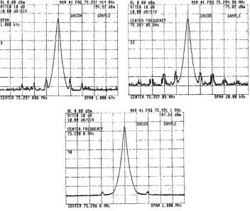
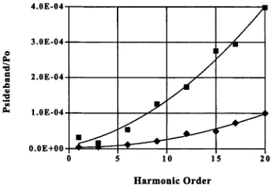
Another possible problem is phase noise in the laser which manifests itself as timing jitter of the output pulses. Timing jitter could create substantial noise problems at the output of the OPO because of variations in the parametric gain caused by the pump pulses moving out of synchronisation with the signal pulses circulating in the OPO resonator. Timing jitter on the pump laser was diagnosed using a fast ( rise time of 2 ns ) Si PIN detector and a spectrum analyser ( 0 to 3 GHz ). Noise sidebands were detected at the laser repetition frequency of 75.4 MHz (and its harmonics) at 100 Hz, ~ 2.3 kHz and weak sidebands at 200 kHz. The 100 Hz sidebands were attributed to noise from the laser's environment ( cooling water, etc ); the 2 kHz to 2.5 kHz sidebands are associated with resonances due to the spontaneous emission lifetime of Nd:YLF2; whilst the origin of the 200 kHz sidebands is unknown. Figure 2-2 shows sample data from the spectrum analyser displaying the different sidebands close to the carrier frequency and its harmonics. Figure 2-3 shows the variation in relative power of the 100 Hz and 2 kHz sidebands increases quadratically with harmonic number. For an imperfectly mode-locked, cw laser the timing jitter in the output pulses will cause the noise sidebands to increase roughly quadratically with increasing harmonic number. This is because the contribution to the temporal intensity profile of a noisy laser pulse from timing jitter is proportional to the time derivative of the intensity of the transform-limited laser pulse. This results in an intensity autocorrelation of the laser pulse with a noise term that increases with repetition time squared [8]. Since the measured power spectrum is the Fourier transform of the intensity autocorrelation function of the noisy
R I 0 .0 8 dSe »KR # i FRQ 7 5 .2 9 ? H19 «Hü 'f lH E S 10 d B ... ' r 1 ... r -9 M .5 7 dB«
L..1B 08 d B /D iy . . .
SPAN __ j ; i T.Mfm"]...|... j
Iw iC Ö R j... T S R l i l f i
„ j....1...L... < - 1 - L I 4
frunhr75T2ST8toriiffi
J..L 8,8.8 dB. i flTTEfi 10 dB i
j a , 08 dB/DIU 4. 4.... f • -4
»KR *1 .FRQ 7 5 .2 9 4 98 U H :.,
SPRNV:888mi J ‘TEHTEff
RL 8 .0 0 dB»
T f r T f r 13 dB.... T '
1.1 0 ,0 8 d B /Q lU ... ;
» N p 4
tüNCdfti... i SftlüjLE.. 1
"CFRltlT 73’.S558 i w i SPÄH 1 .8 0 3 MH:
Figure 2-2 : The phase noise sidebands on the Antares Nd:YLF laser repetition frequency of 75.4 MHz. There were three different sideband frequencies detected; The top left shows sidebands at 100 Hz from the central frequency, the top right shows sidebands at 2 kHz and the bottom shows sidebands at ~ 200 kHz. The vertical scale is 10 dbm per division.
laser pulse, the noise in the power spectrum will increases quadratically with harmonic number if timing jitter is significant. Using calculations from [8] it was found that the timing jitter was to 1.3 ps due to the 100 Hz sidebands; 2.8 ps for the 2.3 kHz sidebands; and 0.76 ps for the 200 kHz sidebands.
However, in all cases the period of the fluctuations ( equal to 1/sideband frequency ) was much greater than the build-up time needed for the OPO to reach steady-state operation. For the highest observed frequency sidebands of 200 kHz the fluctuation period is 5}is. In this time the signal in the OPO makes 377 passes through the crystal. Since the OPO requires roughly 30 to 35 passes to reach threshold it can compensate for any changes in repetition rate of the pump pulses for fluctuation rates less than 2 MHz, much higher than any fluctuation frequency observed.
2.3 The pulse compressor
The design of the fibre-grating pulse compressor follows the work of Chung and Siegman
[image:22.508.88.440.35.331.2]4.0E-04
3.0E-04
2.0E-04
l.OE-04
O.OE+OO
Harmonic Order
Figure 2-3 : The variation of the relative power of the 2.3 kHz and 100 Hz frequency sidebands with increasing harmonic order. The squares are for the 2.3 kHz sidebands and the triangles are for the 100 Hz. P0 is the peak power of the harmonic of the fundamental frequency.
2.3.1 Theory
2.3.1.1 Self-phase modulation
Any fibre-grating pulse compressor relies upon Seif -Phase Modulation (SPM) inside the optical fibre to both increase the spectral bandwidth of the pulse and to produce a roughly linear frequency chirp across the pulse. A frequency-dependent optical delay line is then used to compensate the chirp thereby compressing the pulse. SPM arises from the optical Kerr effect which describes a nonlinear, intensity dependent change in the refractive index of a material. ( See [10] for more details ). That is:
n = rio + m l
For S i02 , n2 =3. 2 x 10'16 cm2/W. This means that the optical Kerr effect only produces significant changes in the properties of a pulse either at very high intensities and/or for propagation over long distances. Both conditions can be achieved during propagation through a single mode optical fibre. The phase change for a pulse propagating through an optical fibre of length L is:
A (f) = m küI{t)L where ko = 2 is the vacuum wavenumber.
As is evident, the phase change for a pulse will be time dependent, reflecting the temporal shape of the pulse propagating in the fibre. This time dependent phase modulation leads to the creation of new frequencies and broadens the pulse spectrum.
[image:23.508.170.362.47.179.2]Time t/,
Figure 2-4 : The intensity temporal profile (left) and instantaneous frequency
(right) of a Gaussian pulse that has only undergone SPM. x is defined in Eqn 2-2.
As can be seen in the figure of the instantaneous frequency the linear frequency
chirp extends from -0.5 tIt to 0.5 t/x. ( Figure taken from [11] )
The frequency broadening is directly proportional to the slope of the pulse profile with time. This means that the central frequency remains unshifted but the frequencies in the leading part of the pulse decrease ( V < VQ ), whilst those in the trailing edge of the pulse
increase ( V > V0 ).
For a Gaussian pulse profile with a FWHM pulse duration of At and peak intensity I0.
I{t) = L exp - 4 In 2
The resulting frequency broadening is
A v (/)= 8 In 2 f — I f
(t)n2 k0L
= 8 1 n 2 f— W ( / )At VA
t.
Figure 2-4 shows the case for the Gaussian pulse profile and the frequency as a function of time resulting from SPM. As can been seen a linear frequency chirp develops across the central section of the spectrum. The maximum frequency shift that results can be estimated as:
Avmax --- A ^ e x p ( - 0 .5 ) (p
To
max = O.858AvoA 0 max
Eqn 2-1
whereT»= % / t o 2 = / ^ o
Eqn 2-2
and
A(t>
max = n 2IQk QL .of the frequency chirp is ~ 0.9 Avmax. SPM only affects the spectrum of the pulse, the temporal profile does not change if SPM is the only effect.
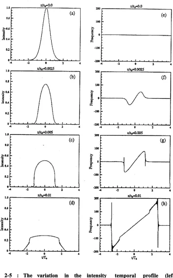
The temporal profile can, however, be affected by Group Velocity Dispersion ( GVD ) if the fibre is sufficiently long. Since a frequency chirp exists across the central portion of the pulse, different parts of the pulse travel with different group velocities. The leading part of the pulse, whose frequencies are lower than the central frequency, travel fastest whilst the trailing edge of the pulse, with frequencies higher than the central frequency, travel slower than the rest of the pulse. The effect of this is that the temporal profile of pulse develops steep trailing and leading edges as the leading part of the pulse “overtakes” the rest of the pulse and the trailing edge is left behind. This eventually leads to the development of a rectangular pulse shape. The steep edges undergo further, strong SPM because of the rapid change in intensity at these points. This leads to creation of new frequencies and the linear frequency chirp spreading from just the central portion to fill the entire pulse. Figure 2-5 illustrates the development of the temporal pulse profile and instantaneous frequency as a Gaussian pulse propagates through an optical fibre with increasing length.
The dispersion length z0 [10] is the length over which GVD becomes significant.
_ 7t2c A t2
Z° " ^|D|
where D is the GVD. Typically D « 30 ps/nm/km for silica and a wavelength X0 near 1 pm. For a pulse of 60 ps , z0~ 300 km. In our case the fibre length is 2 x 10'5 z0 so, GVD plays no effect in these experiments since the length of the optical fibre used is much less than z0 . SPM is the dominant effect in this experiment.
2.3.1.2 Stimulated Raman scattering
There are limits to how much power can be launched into a fibre. The limits are due to thermal loading from the high average power of the laser or due to the onset of undesirable nonlinear processes occurring due to the high peak powers.
It was found that the fibre could suffer failure due to the high average power affecting its plastic cladding. Specifically, it was found that the soft plastic jacket melted and eventually broke the fibre through local heating. As will be described later, this problem was eventually solved by encapsulating the fibre in a index matched jacket to ensure any radiation in the cladding did not couple to the plastic encapsulation.
Figure 2-5 : The variation in the intensity temporal profile (left) and
instantaneous frequency (right) as a function of time/pulse duration (t/T0) of a
Gaussian pulse as it propagates in a single mode optical fibre undergoing the
effects of SPM and GVD. (a) and (e) are respectively, the initial temporal
intensity distribution and frequency distribution with time of a Gaussian pulse,
(b) and (f) display the temporal profile and instantaneous frequency after
propagating 0.0025 z0 . (c) and (g) display the temporal profile and instantaneous frequency after propagating 0.005 z0 . (d) and (h) display the temporal profile and
instantaneous frequency after propagating 0.01 z0 . GVD extends the frequency
[image:26.508.90.442.51.615.2]Figure 2-6 : The photo on the left displays the SPM power spectrum of the pulse from the Antares Nd:YLF laser at a cw power of 0.94 W focussed into a 45 m length of single-mode fibre. The photo on the right is the SPM power spectrum of
the pulse at 1.4 W cw. SRS has depleted the higher wavelength side of the
spectrum, shifting energy into a Stokes wave at ~ 1120 nm. The scale is 6.25 Angstroms per division.
In this equation A is the fibre core area, g is the Raman gain coefficient =4. 5 x 10'14 m/W and L is the length of the fibre. This simply formula gives a indicator of the maximum peak power that can propagate through a fibre of length L before SRS becomes an important consideration. Figure 2-7 shows how the fibre length was chosen experimentally to provide maximum spectral bandwidth ( which is dependent on the peak power of the 1054 nm pulse coupled into the fibre ) while minimising SRS. As shown in the figure the SRS power is inversely proportional to the fibre length while the SPM induced spectral bandwidth is directly proportional to the fibre length, as expected. As will be later shown the chosen fibre length is long enough to be able to compress the 1054 nm pulses down to the desired ~ 2.5 ps in duration while coupling the maximum possible peak power into the fibre and being short enough to minimise SRS.
2.3.1.3 Grating compressors
After the fibre, a grating compressor provided anomalous ( negative ) GVD to counteract the normal dispersion ( positive ) frequency chirp to compress the pulse. The compressor has the property that the leading part of the pulse, which has lower frequencies, travels further than the trailing part of the pulse, which has higher frequencies. This difference in path length allows the trailing part of the pulse to catch up to the leading part of the pulse thereby compressing the pulse in time. To first approximation the delay is a linear function of frequency. However, since the pulse contains an approximately linear frequency chirp only near its centre, some of the pulse energy cannot be compressed and creates a low power pedestal and sidelobes ( See [10] for more details ).
« = -1 . 0
Fibre Length (m)
Figure 2-7 : This graph shows the spectral bandwidth (squares) of the pulse, after propagating through a length of fibre, at the point were the Stoke’s wave becomes detectable (diamonds). The left vertical axis shows the bandwidth and the left vertical axis shows the full cw power coupled out of the fibre when the Stoke’s wave becomes detectable. As can be seen the bandwidth increases linearly with fibre length, whereas, the power threshold for the onset of SRS is proportional with 1/ fibre length.
Since the grating compressor uses anomalous dispersion to delay the frequency components of the pulse so that they all emerge from the compressor at the same time, the separation of the grating pair is critical to successfully compressing the pulse. The grating separation can be estimated by setting the anomalous dispersion due to the grating equal to the dispersion due to the frequency chirp in the pulse. The quadratic dispersion of a grating pair is ( see [14] )
GL =
bx
ay
2juc11d . 1- ( - - S i n O ,
r 3
/
Eqn 2-3
where b is the grating separation, d is the grating period and 0j is the angle of incidence. The dispersion of the frequency chirped pulse can be estimated to be
a
p T0.9A
co
maxEqn 2-4
where Acomax = 27tAvmax . Avmax and x have been defined in Eqn 2-1 and Eqn 2-2.
A 1200 line/mm grating was chosen for the pulse compressor because it gave a conveniently small grating separation, but also because a grating with a smaller period would have introduced a larger distortion in the compressed pulse due to a larger cubic term in the grating response. Cubic phase shifts are due to the next higher order in the dispersion of the grating pair. A condition for minimum distortion from the cubic orders is ( see [14] )