Coherent imaging using laser feedback
interferometry with pulsed-mode terahertz
quantum cascade lasers
Y
AHL
ENGL
IM,
1,5K
ARLB
ERTLING,
1,5T
HOMAST
AIMRE,
2,5T
IMG
ILLESPIE,
3C
HRISG
LENN,
3A
SHLEYR
OBINSON,
3D
RAGANI
NDJIN,
4Y
INGJUNH
AN,
4L
IANHEL
I,
4E
DMUNDH. L
INFIELD,
4A.
G
ILESD
AVIES,
4P
AULD
EAN,
4 ANDA
LEKSANDARD. R
AKI ´C1,*1School of Information Technology and Electrical Engineering, The University of Queensland, Brisbane, QLD 4072, Australia
2School of Mathematics and Physics, The University of Queensland, Brisbane, QLD 4072, Australia 3L3 Micreo, 7 Hi-Tech Court, Brisbane Technology Park, Eight Mile Plains, QLD 4113, Australia 4School of Electronic and Electrical Engineering, University of Leeds, Leeds LS2 9JT, UK 5These authors contributed equally to the paper
Abstract: We report a coherent terahertz (THz) imaging system that utilises a quantum cascade laser (QCL) operating in pulsed-mode as both the source and detector. The realisation of a short-pulsed THz QCL feedback interferometer permits both high peak powers and improved thermal efficiency, which enables the cryogen-free operation of the system. In this work, we demonstrated pulsed-mode swept-frequency laser feedback interferometry experimentally. Our interferometric detection scheme not only permits the simultaneous creation of both amplitude and phase images, but inherently suppresses unwanted background radiation. We demonstrate that the proposed system utilising microsecond pulses has the potential to achieve 0.25 mega-pixel per second acquisition rates, paving the pathway to video frame rate THz imaging.
Published by The Optical Society under the terms of theCreative Commons Attribution 4.0 License. Further distribution of this work must maintain attribution to the author(s) and the published article’s title, journal citation, and DOI.
1. Introduction
Terahertz (THz) frequency (∼0.1–10 THz) radiation is attractive for a diverse range of imaging and sensing applications due to the unique properties of THz waves. These include the ability to penetrate many visually-opaque materials, the characteristic THz spectral responses of a wide range of organic and inorganic materials, and the non-ionizing nature of THz radiation. The development of reflection-mode, non-invasive and fast THz imaging systems [1, 2], in particular, is essential for the realisation of key applications in the realms of biomedical imaging [3–10], security screening [11–15], and non-destructive industrial inspection [16, 17].
In order to unlock these potential applications a high contrast and cost-effective THz imaging system should meet several key requirements: (1) high emitted THz power enabling greater transmission through barrier materials; (2) high frame rate; and (3) adequate resolution. Sub-THz (< 1 THz) imaging systems exist but their achievable resolution is lacking due to the long wavelength [13], whereas systems based on THz time domain approaches typically lack sufficient power or suffer from slow signal acquisition [18–20].
The only practical solution for achieving high power THz illumination with a compact source is to employ a THz QCL [21–24]. Terahertz QCLs are coherent sources of radiation that operate in the frequency range∼1.2–5 THz and with peak powers up to∼2.4 W [25] (at 4.4 THz). Using a THz QCL as an illumination source allows for higher resolution imaging than sub-THz systems (due to the shorter wavelength) and many orders of magnitude more power (>100 mW) than typical time-domain systems [26]. Therefore, the THz QCL is emerging as an obvious
illumination source for high sensitivity THz imaging systems. The most direct approach is to use an external single-pixel detector in a scanning configuration (see [21] and references therein). However, such systems require relatively complicated optical setup and careful alignment of the QCL source and the detector.
One way to alleviate this problem is to use an array of external detectors to create a THz camera [1, 27]. Recent years have seen significant work on the development of THz cameras including the use of microbolometer arrays [28–33], pyroelectric sensor arrays [34–36], and CMOS detectors [37]. Microbolometer-based cameras provide the only viable choice for both high speed and high sensitivity imaging. Consequently, the current state of the art solution for a fast high-resolution THz imaging system is to utilise a THz QCL as an illumination source and a microbolometer-based THz camera as a detector. This approach, however, introduces several notable challenges. Specifically, the illumination optics must be designed carefully in order to expand the beam (for complete target illumination), ensure uniform target illumination, and break the coherence of the illuminating THz beam. If these criteria are not met, the resulting images will be plagued by the presence of interference fringes, speckle, and similar coherent imaging artefacts [38]. Finally, most thermal detectors such as microbolometers are incoherent, and consequently cannot resolve the phase.
One approach to avoid these problems is through the use of digital holography techniques, exploiting the coherent nature of the THz QCL source [39–41]. Unfortunately, the very nature of holographic imaging systems means that the fixed imaging field can be restrictive for non-cooperative targets. Moreover, image formation from recorded holograms can be computationally expensive. Additionally for all schemes that use an external detector, including THz cameras, the detectors are sensitive not only to the illuminating THz QCL, but are also sensitive to radiation from unwanted illumination sources (although this can be mitigated by using a lock-in amplifier).
Demonstrably, there is an imaging solution that is well suited to fast imaging and suppresses unwanted background radiation, whilst also harnessing the coherent nature of the illumination source. Laser feedback interferometry (LFI) employing a THz QCL as both the source and detector of the radiation enables the development of a compact, self-aligned, single pixel interferometric imaging system.
This technique has been applied with great success to three-dimensional target reconstruction [42,43], materials analysis of remote targets [44–48], and a combination of amplitude and phase-contrast imaging concurrently [49–51]. However, the majority of LFI imaging implementations to date have been limited to a low frame rates of a few frames per second [51, 52]. Moreover, these systems are typically reliant on QCL devices operating in continuous-wave (CW) mode (with a notable exception being [52], which employs a sophisticated scheme using a THz amplifier with a pulsed QCL) and hence requiring large electrical driving power that contribute significantly to Joule heating of the device. Ultimately, this results in smaller peak THz powers and a requirement for significantly lower operating (heat sink) temperatures when compared to pulsed-mode QCLs [22, 24]. One might like to highlight that pulsed LFI operation makes it possible to use pulsed-only QCLs. This elevates the operating temperature range accessible to the LFI scheme [22], and increases the peak emitted power from the device without increasing the average dissipated power and the demand on the cooling system. Moreover, all other parameters of the system being the same, the high emitted power leads to an improved signal-to-noise ratio.
at high speed is that simple filtering is rendered ineffective for isolating the SM signal. High speed operation comes with additional challenges, including proper impedance matching to avoid distortion of the driving current waveform and subsequent recovery of resulting voltage SM signal. Utilizing a QCL for LFI heightens this challenge, as operating QCLs requires large current and thus high electric power, thereby increasing the importance of impedance matching and complexity of voltage signal recovery. Furthermore, the high current levels pose additional challenges to achieving fine control and stability of the current drive waveform, both of which are absolutely critical for the creating the correct swept-frequency SM signal.
Hence there is a clear need to develop an LFI imaging solution that uses short drive pulses while increasing the pixel acquisition rate, making video frame rate imaging possible. Our recent modelling work demonstrates the feasibility of this scheme [53–55]. Moreover, this operating regime provides increased immunity to motion artefacts (including mechanical vibration of the transceiver and movement of the target). Furthermore, we highlight that such a solution would make it possible to use pulsed-only QCLs, which would elevate the operating temperature range accessible to the LFI scheme in addition to permitting the use of CW QCLs in pulsed-mode.
In this article we demonstrate a pulsed-mode LFI imaging system built around a THz QCL operating as a homodyning transceiver in a compact mechanical cryogen-free Stirling cooler. The interferometric nature of the LFI imaging scheme inherently provides high sensitivity and suppression of background radiation, thereby permitting high contrast imaging and the concurrent extraction of both amplitude and phase information of an external target. At the same time, the microsecond pulsed-mode operation of our system opens the way for the development of a high-speed video frame rate THz imager.
2. Laser feedback interferometry
Laser feedback interferometry, also known as SM interferometry, is a coherent sensing scheme that employs a laser as a homodyne transceiver. Laser feedback interferometry relies on the remarkably universal SM effect — the sensitivity of a coherent source to its emitted electromagnetic field that interacts with the environment external to the laser and is partially reinjected to the source. The scheme offers the inherent advantages of high sensitivity, suppression of background radiation, and simple optical configuration. These benefits of LFI have been exploited across a wide range laser systems for sensing and imaging applications spanning the visible to THz regions of the spectrum, and in particular has been championed by Donati and coworkers [56,57]; see [58] for a comprehensive overview. To date, most experimental demonstrations of LFI employ CW laser sources. When THz QCLs are the sources of choice, the benefits of LFI over alternative coherent sensing schemes become most pronounced. This is a consequence of the combination of a simple optical configuration that does not rely on the use of bulky and expensive cryogenically-cooled detectors, yet offers wide detection bandwidths, low phase noise and high detection sensitivity. The SM signal observable in LFI is typically monitored via the laser terminal voltage [59, 60]. This signal depends on both the strength (amplitude) and the phase of the reinjected wave; the former of these relates to the target reflectivity whereas the latter is dependent on the external cavity length (distance to target or equivalent) and provides phase information about the external target [61]. The coherent nature of the LFI detection scheme enables the extraction of this complex pair. As demonstrated in our previous work, one convenient means to achieve this through a swept-frequency approach in which a frequency modulation is applied to the QCL source [45] to concurrently register and isolate target amplitude and phase information. These techniques enable LFI to be used with THz QCLs for a variety of applications [62–67].
(a)
T Piece Cold Finger
PCB
QCL Sub-CarrierQCL
Sub-Carrier
Integrated QCL Carrier
(b)
QCL
QCL
(c)
Target
L1 L2
Polarizer Stirling
Cooler PC
Temp Control
Tapered Transmission
Line
RTO1024 12-bit ADC
500MS/s
Negatised Signal
QCL Pulse Driver
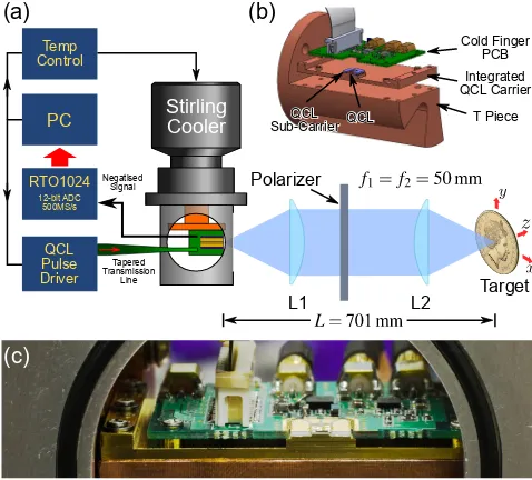
Fig. 1. (a) Schematic diagram of the experimental setup. (b) Expanded view of the QCL cold finger module. (c) Photo of the THz QCL mounted on the cold finger of the Stirling cooler.
challenge identified in this previous work was that the expected amplitude of the SM signal was three to four orders of magnitude smaller than the corresponding drive pulse amplitude. As such, new engineering solutions are required to isolate the SM signal from the large drive pulse transient.
3. Experimental setup
The QCL used consisted of a 12 µm-thick GaAs/AlGaAs 9-well phonon-assisted active region with a design frequency of∼2.9–3.2 THz [69]. The active region layer structure starting from the injection barrier was4/10.1/0.5/16.2/1/12.9/2/11.8/3/9.5/3/8.6/3/7.1/3/17/3/14.5 nm. The structure was grown by solid-source molecular beam epitaxy on a semi-insulating GaAs substrate, with the active region grown between doped upper 50 nm-thick (n=5×1018cm−3)
and lower 700 nm thick (n=2×1018 cm−3) GaAs contact layers. The wafer was processed
into 150 µm wide surface-plasmon ridge waveguide structures using photolithography and wet chemical etching, with the substrate thinned to∼200 µm. Devices were then mechanically cleaved to define a ridge of length 2 mm.
Figure 1 shows the experimental arrangement of our imaging system, along with key components of the custom laser pulse driver built by L3 Micreo Ltd. Figure 1(b) depicts an expanded view of the custom-built QCL cold finger module mounted on a copper T-piece, which was attached to the cold finger of a mechanical Stirling cryocooler (Cryotel GT, Sunpower, Inc.) within a custom built cryostat. The QCL cold finger module consisted of three key components: 1) the integrated QCL carrier; 2) the QCL sub-carrier; and 3) the cold finger PCB. The integrated QCL carrier was a gold plated copper carrier with an elevated ridge onto which the THz QCL was directly bonded using indium. The QCL sub carrier was mounted around this ridge and consisted of several electrically-isolated gold pads on an alumina carrier. The cold finger PCB in turn enveloped the QCL sub-carrier and was fastened onto the integrated QCL carrier.
[image:4.612.187.426.96.312.2]between the QCL terminals and the QCL sub carrier, with a further set of bonds connecting the QCL sub carrier to the cold finger PCB. The cold finger PCB in turn was connected to the laser pulse driver with a set of tapered transmission lines and coaxial cables via sealed access ports on the cryostat.
The operating point of the Stirling engine was set to 50 K. This operating point was chosen to maximise the frequency sweep range of the QCL while ensuring the cooler operated at a viable cooling capacity. Vibrations along the optical axis caused by the Stirling cooler were measured to be (∼5 µm), predominantly at a low frequency of 60 Hz. Radiation from the QCL was collimated and focused on the target using a pair of Tsurupica plastic lenses with 50 mm focal length and 30 mm clear aperture (Tsurupica-RR-CX-1.5-50-SPS, Broadband, Inc.). The total optical path between the QCL source and the target was 701 mm through an ambient (unpurged) atmosphere.
The laser was driven using a custom-built laser pulse driver. This piece of hardware both generated the current pulses to drive the laser as well as recovered the small SM signal superimposed on the resulting voltage pulse measured across the laser. The laser pulse driver consisted of a main controller board [with a field-programmable gate array (FPGA) controlling the pulse generation] and SM signal extraction electronics, the QCL cold finger module within the cryostat, and the tapered transmission lines (16Ωdown to 4Ω) that were used to deliver the fast current pulses to the QCL cold finger module. The cold finger PCB on the QCL cold finger module also included additional electronic circuitry for conditioning the signal and returned the partially conditioned signal to the main controller board via the coaxial cables. The cold finger PCB was placed in close proximity to the QCL in order to maximise bandwidth and reduce signal distortion due to impedance mismatch, which are important design considerations for high-speed performance.
The QCL was driven with a train of current pulses, each consisting of a large square current pulse to which a small current ramp could be introduced. Two current pulse shapes were used in this work: a square pulse with amplitude∼1.2 A; and a square pulse from which a small linear current ramp was subtracted, resulting in a ramped driving pulse covering the range from∼1.4 A to∼1.1 A (300 mA current sweep). Bysubtractingthe current ramp in this way we ensured that the thermal and adiabatic frequency modulation effects were constructive for this particular QCL device (as predicted in [55]). Moreover, the starting current for the ramped pulse (i.e.∼1.4 A) was chosen to maximise the mode hop-free tuning range of the QCL. Additionally, a wire grid polariser (G30-L, Microtech Instruments, Inc.) was used as a variable attenuator to maintain the level of optical feedback within the weak feedback regime, since at moderate to strong optical feedback levels the SM signal was found to be complicated by the presence of multiple cavity modes and mode hopping during the current sweep.
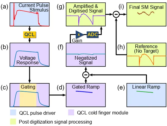
Figure 2 illustrates the signal conditioning path used to extract the SM signal from the voltage pulse measured across the laser. The first step is to generate the current pulse that drives the QCL, which is delivered to the laser via the tapered transmission lines [Fig. 2(a)]. This current pulse creates a voltage response which contains the small SM signal superimposed on a large voltage pulse (∼7 V) [Fig. 2(b)]. In CW implementations of swept frequency LFI [45], the large voltage offset across the laser is a DC voltage that can be removed easily via AC coupling. However, in this implementation the spectral content of the driving pulse overlaps significantly with the spectrum of the SM signal, rendering simple filtering ineffective for isolating the SM signal.
Current Pulse Stimulus
Linear Ramp QCL
Voltage Response
Gain
Gated Ramp
Reference (No Target) ADC
Final SM Signal Amplified &
Digitised Signal
Negatized Signal X
Gating
QCL cold finger module QCL pulse driver
Post digitization signal processing (a)
(b)
(c)
(g)
(f)
(d)
(i)
(h)
[image:6.612.169.443.95.302.2](e)
Fig. 2. Flow diagram illustrating the signal conditioning performed by the custom built laser pulse driver (see text for detailed description).
as artefacts brought about by the driving circuit [Fig. 2(f)]. This signal is then amplified and digitised using a Rohde & Schwarz RTO1024 oscilloscope [Fig. 2(g)]. The bandwidth of the RTO1024 was restricted to 500 MS/s at 12-bit resolution in order to emulate the performance of low-cost, commercially available ADCs such as Analog Devices AD9434BCPZ-500. In order to extract the SM signal from the negatized signal, we acquire a reference trace from the QCL with no optical feedback (i.e. a negatized signal from the free-running laser) by blocking the front window of the cryostat. The reference trace is taken only once at system start-up and does not need to be repeated for each image frame nor individual pixel. This negatized trace is digitally subtracted from subsequently measured traces [Fig. 2(h)], resulting in the final isolated SM signal [Fig. 2(i)]. For image acquisition, the target was raster-scanned in two dimensions using a two-axis computer-controlled translation stage. Time domain traces were acquired at each node of a square grid with common pitch of 100 µm.
4. Experimental results
A series of experiments were first carried out to investigate the effect of pulse shape and duration on the integrity of the SM signal. Figure 3 shows exemplar SM signals recorded with six different driving pulse conditions; a combination of two pulse shapes (square pulses and ramped pulses) and three pulse durations spanning approximately 3 orders of magnitude (∼300, 20, and 1 µs, at 10% duty cycle) were used. As can be seen [broken lines in Figs. 3(a)–3(c)] a SM signal is created even when the laser is driven by a simple square pulse. This signal arises due to thermally-induced frequency tuning of the QCL.
0 100 200 300 400 Time (uS)
0 2 4 6 8 V oltage ( V) 0 0.5 1 1.5 2 Curr ent (A)
0 10 20 30
Time (uS) 0 2 4 6 8 V oltage ( V) 0 0.5 1 1.5 2 Curr ent (A)
0 0.5 1 1.5 2
Time (uS) 0 2 4 6 8 V oltage ( V) 0 0.5 1 1.5 2 Curr ent (A)
50 100 150 200
-20 -10 0 10 20 Extracted S M Sign al (mV )
5 10 15 20 25
-20 -10 0 10 20 Extracted S M Sign al (mV )
0.8 1 1.2
-20 -10 0 10 20 Extracted S M Sign al (mV )
Time (uS) Time (uS) Time (uS)
(a)
(b)
[image:7.612.132.476.171.556.2](c)
(a) (b)
Fig. 4. THz images of an Australian $1 Coin using∼1 µs pulses at 10 % duty cycle with 100 µm scanning pitch. (a) Amplitude and (b) phase images from an array of SM signals.
be explained by a reduced thermal frequency modulation for shorter driving pulses. All of these observed behaviours agree qualitatively with the behaviour predicted in our recent modelling work [53–55].
The data shown in Fig. 3 also allows us to answer one key question — what is the shortest driving pulse that creates a viable SM signal? Demonstrably, even the∼1 µs ramped pulse contains sufficient information to obtain a good quality SM signal. Therefore, extremely fast pixel acquisition is possible, as illustrated by the imaging results presented below.
The use of short pulses also offers increased immunity to mechanical vibrations or target motion. This immunity comes about since the short∼1 µs pulse duration is several orders of magnitude faster than typical mechanical vibrations in our system (which are≤10 kHz). Even when averaging over a series of pulses, the total acquisition time for the trace remains at least one order of magnitude faster. Consequently, there is no observable detrimental effect from mechanical vibration of the cryocooler on the SM signal.
To demonstrate the practical performance of the proposed pulse-mode LFI imaging system, we imaged a 2018 $1 AUD coin. Figure 4 shows the results of a 261×261 scan with 100 µm pitch, using a∼1 µs pulse at 10% duty cycle with 16×waveform averaging. Amplitude [Fig. 4(a)] and phase [Fig. 4(b)] images were created by using the amplitude and phase of the fast Fourier transform evaluated at the fundamental frequency of the SM signal [43]. As evidenced by these images, the phase in particular is extremely stable, which we attribute to the very short pulse duration used here; indeed, even with 16×averaging, the effects of any mechanical vibrations are not observable in the recorded images.
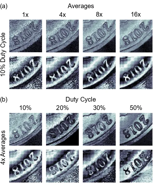
We also explored the impact of a range of operating conditions on the practical performance of the imaging system. A series of eight scans was carried out on a small portion of the coin: Fig. 5(a) shows amplitude (top row) and phase (bottom row) images recorded with varying degrees of waveform averaging at each pixel (1×, 4×, 8×, and 16×) for a fixed pulse duty cycle (10%); whereas Fig. 5(b) shows amplitude (top row) and phase (bottom row) images for different pulse duty cycles (10%, 20%, 30%, and 50%) with a fixed number of waveform averages (4×). As can be seen, all operating scenarios tested produced clearly visible images in Fig. 5 — even in the cases with no waveform averaging. Unlike the series of phase images recorded for varying degrees of averaging, there is an observable shift in the phase of the fringes as the duty cycle increases; we attribute this to a change in wavelength of the QCL as a result of higher average lattice temperature.
4x
A
verage
s
20%
10% 30% 50%
Duty Cycle
1x 4x 8x 16x
10% Duty Cycle
Averages (a)
[image:9.612.184.428.91.387.2](b)
Fig. 5. Amplitude (top rows) and phase (bottom rows) THz images of the numerals ‘2018’ on an Australian $1 Coin. (a) 1×, 4×, 8×, and 16×averaging (10% duty cycle,∼1 µs pulse width). (b) 10%, 20%, 30%, and 50% duty cycle with a∼1 µs pulse width (4×averaging).
5. Discussion
In this work, we have demonstrated the feasibility of a high-speed pulsed-mode LFI imaging system based on a THz QCL operating as a single pixel coherent detector — a necessary prerequisite for video frame rate image formation. By operating with short pulses, down to ∼1 µs duration, the system enjoys increased immunity to motion artefacts; this has the additional benefit of reducing the impact of (relatively) slow temporal changes in the external cavity such as mechanical variations due to atmospheric or temperature fluctuations. It should be noted that there is a trade-off between the pulse duty cycle employed and the required cooling capacity — for a fixed pulse width, a lower duty cycle requires reduced cooling capacity but places an upper limit on the pixel acquisition rate; the practical implication of this is that one could sacrifice imaging speed for use of a cryocooler that is more compact, less expensive, and has lower power consumption.
There is also a trade-off between the number of waveform averages employed and the noise level of the resulting image — increasing the number of averages decreases the upper limit on pixel acquisition rate with the benefit of reducing image noise, as shown in Fig. 5(a).
With the current system, there are two limiting factors to achieving video frame rate imaging. The first limiting factor is the speed of controlling the two-axis translation stage used in our system — to communicate and move the stage to each pixel position takes∼30 ms. This problem is not unique to our single pixel THz imaging system. Pathways to solutions exist in the literature for systems similarly employing THz QCL sources and using a variety of detection schemes, including LFI [51, 52], those utilising external detectors [71], and THz Radar [13]. In this respect, we emphasise here that our pulsed LFI scheme enjoys increased immunity to pixel motion artefacts which are commonly observed in fast scanner systems. The second limiting factor is the speed of data acquisition — taking up to∼100 ms per pixel for the oscilloscope used here (RTO1024). This factor could be readily overcome by using a commercially available ADC interfaced with the FPGA on the custom built laser pulse driver.
Our data demonstrates that the present system can operate comfortably with a∼1 µs pulse at 30% duty cycle with no waveform averaging. This corresponds to an acquisition time of 4 µs per pixel, or equivalently 0.25 M pixel/s [or 62.5 k pixel/s with 4×averages, for more robust images]. Thus, in principle, a 101 × 101 image could be generated at 24 fps [6 fps] if these two limiting factors are overcome.
We envisage that high-speed pulsed-mode LFI sensors would become even more appealing by utilising a THz QCL source with wide frequency-tuning capacity, in particular a coupled-cavity THz QCL. These sources open up the potential for high-speed hyperspectral THz imaging, with potential for frequency jumps from pulse to pulse [72,73] — effectively creating a high-speed pulsed-mode multiplexed hyperspectral THz imaging system.
6. Conclusions
We have demonstrated a coherent THz imaging system that utilises a QCL operating in pulsed-mode as both the source and detector. Our scheme relies on the novel use of LFI in conjunction with microsecond pulsing to extract both amplitude and phase information of an external target concurrently. The use of a pulsed THz QCL in conjunction with the LFI detection scheme has several desirable characteristics including: higher temperature operation of the THz QCL enabling the use of a mechanical Stirling cryocooler; high THz powers; immunity to background radiation; coherent detection, permitting the concurrent acquisition of both amplitude and phase images; and increased immunity to motion artefacts. We have successfully applied this approach to coherent image acquisition with pulse durations down to∼1 µs. For these microsecond pulses with high duty cycle and low averaging the acquisition rate approaches mega-pixels per second, suitable for video-frame-rate imaging.
Funding
Australian Research Council Discovery Project (DP160103910); Engineering and Physical Sciences Research Council (EPSRC), UK (HyperTerahertz programme EP/P021859/1); European Cooperation in Science and Technology (COST) (BM1205 Action), Queensland Government’s Advance Queensland Program; the Royal Society and Wolfson Foundation.
References
1. D. M. Mittleman, “Twenty years of terahertz imaging,” Opt. Express26, 9417–9431 (2018).
2. H. Guerboukha, K. Nallappan, and M. Skorobogatiy, “Toward real-time terahertz imaging,” Adv. Opt. Photon.10,
843–938 (2018).
4. E. Pickwell and V. Wallace, “Biomedical applications of terahertz technology,” J. Phys. D: Appl. Phys.39, R301
(2006).
5. A. D. Rakic, T. Taimre, K. Bertling, Y. L. Lim, S. J. Wilson, M. Nikolic, A. Valavanis, D. Indjin, E. H. Linfield, A. G. Davies, B. Ferguson, G. Walker, H. Schaider, and H. P. Soyer, “THz QCL self-mixing interferometry for biomedical applications,” Proc. SPIE9199, 9199M (2014).
6. C. Yu, S. Fan, Y. Sun, and E. Pickwell-MacPherson, “The potential of terahertz imaging for cancer diagnosis: A review of investigations to date,” Quant. Imaging Med. Surg.2, 33–45 (2012).
7. J. E. Mayer and B. B. Adams, “Nodular melanoma serendipitously detected by airport full body scanners,” Dermatology
230, 16–17 (2015).
8. A. D. Rakic, Y. L. Lim, T. Taimre, G. Agnew, X. Qi, K. Bertling, S. Han, S. J. Wilson, I. Kundu, A. Grier, Z. Ikonic, A. Valavanis, A. Demic, J. Keeley, L. H. Li, E. H. Linfield, A. G. Davies, P. Harrison, B. Ferguson, G. Walker, T. Prow, D. Indjin, and H. P. Soyer, “Optical feedback effects on terahertz quantum cascade lasers: modelling and applications,” Proc. SPIE10030, 1003016 (2016).
9. P. Caine, M. U. Javed, and R. O. S. Karoo, “A desmoplastic melanoma detected by an airport security scanner,” J. Plast. Reconstr. Aesthet. Surg.69, 874–876 (2016).
10. G. Hernandez-Cardoso, S. Rojas-Landeros, M. Alfaro-Gomez, A. Hernandez-Serrano, I. Salas-Gutierrez, E. Lemus-Bedolla, A. Castillo-Guzman, H. Lopez-Lemus, and E. Castro-Camus, “Terahertz imaging for early screening of diabetic foot syndrome: A proof of concept,” Sci. Rep.7, 42124 (2017).
11. R. Appleby and H. B. Wallace, “Standoff detection of weapons and contraband in the 100 GHz to 1 THz region,” IEEE Trans. Antennas Propag.55, 2944–2956 (2007).
12. H.-B. Liu, H. Zhong, N. Karpowicz, Y. Chen, and X.-C. Zhang, “Terahertz spectroscopy and imaging for defense and security applications,” Proc. IEEE95, 1514–1527 (2007).
13. K. B. Cooper, R. J. Dengler, N. Llombart, B. Thomas, G. Chattopadhyay, and P. H. Siegel, “THz imaging radar for standoff personnel screening,” IEEE Trans. THz Sci. Technol.1, 169–182 (2011).
14. H. Hoshina, Y. Sasaki, A. Hayashi, C. Otani, and K. Kawase, “Noninvasive mail inspection system with terahertz radiation,” Appl. Spectrosc.63, 81–86 (2009).
15. M. Kemp, “Screening mail for powders using terahertz technology,” Proc. SPIE8189, 81890J (2011).
16. R. Fukasawa, “Terahertz imaging: Widespread industrial application in non-destructive inspection and chemical analysis,” IEEE Trans. THz Sci. Technol.5, 1121–1127 (2015).
17. M. Stecher, C. Jördens, N. Krumbholz, C. Jansen, M. Scheller, R. Wilk, O. Peters, B. Scherger, B. Ewers, and M. Koch, “Towards industrial inspection with THz systems,” inUltrashort Pulse Laser Technology(Springer, 2016),
pp. 311–335.
18. M. Naftaly, “Metrology issues and solutions in THz time-domain spectroscopy: Noise, errors, calibration,” IEEE Sensors J.13, 8–17 (2013).
19. M. C. Kemp, “Explosives detection by terahertz spectroscopy – a bridge too far?” IEEE Trans. THz Sci. Technol.1,
282–292 (2011).
20. H. Guerboukha, K. Nallappan, and M. Skorobogatiy, “Exploiting k-space/frequency duality toward real-time terahertz imaging,” Optica5, 109–116 (2018).
21. P. Dean, A. Valavanis, J. Keeley, K. Bertling, Y. Lim, R. Alhathlool, A. Burnett, L. Li, S. Khanna, D. Indjin, T. Taimre, A. D. Rakic, E. H. Linfield, and A. G. Davies, “Terahertz imaging using quantum cascade lasers – a review of systems and applications,” J. Phys. D: Appl. Phys.47, 374008 (2014).
22. M. S. Vitiello, G. Scalari, B. Williams, and P. De Natale, “Quantum cascade lasers: 20 years of challenges,” Opt. Express23, 5167–5182 (2015).
23. Editorial, “Quantum cascade celebration,” Nat. Photon.8, 577 (2014).
24. S. S. Dhillon, M. S. Vitiello, E. H. Linfield, A. G. Davies, M. C. Hoffmann, J. Booske, C. Paoloni, M. Gensch, P. Weightman, G. P. Williams, E. Castro-Camus, D. R. S. Cumming, F. Simoens, I. Escorcia-Carranza, J. Grant, S. Lucyszyn, M. Kuwata-Gonokami, K. Konishi, M. Koch, C. A. Schmuttenmaer, T. L. Cocker, R. Huber, A. G. Markelz, Z. D. Taylor, V. P. Wallace, J. A. Zeitler, J. Sibik, T. M. Korter, B. Ellison, S. Rea, P. Goldsmith, K. B. Cooper, R. Appleby, D. Pardo, P. G. Huggard, V. Krozer, H. Shams, M. Fice, C. Renaud, A. Seeds, A. Stohr, M. Naftaly, N. Ridler, R. Clarke, J. E. Cunningham, and M. B. Johnston, “The 2017 terahertz science and technology roadmap,” J. Phys. D: Appl. Phys.50, 043001 (2017).
25. L. H. Li, L. Chen, J. R. Freeman, M. Salih, P. Dean, A. G. Davies, and E. H. Linfield, “Multi-watt high-power THz frequency quantum cascade lasers,” Electron. Lett.53, 799–800 (2017).
26. L. Li, L. Chen, J. Zhu, J. Freeman, P. Dean, A. Valavanis, A. G. Davies, and E. H. Linfield, “Terahertz quantum cascade lasers with >1 W output powers,” Electron. Lett.50, 309–311 (2014).
27. E. Hack, L. Valzania, G. Gäumann, M. Shalaby, C. P. Hauri, and P. Zolliker, “Comparison of thermal detector arrays for off-axis THz holography and real-time THz imaging,” Sensors16, 221 (2016).
28. A. W. Lee and Q. Hu, “Real-time, continuous-wave terahertz imaging by use of a microbolometer focal-plane array,” Opt. Lett.30, 2563–2565 (2005).
29. A. W. M. Lee, B. S. Williams, S. Kumar, Q. Hu, and J. L. Reno, “Real-time imaging using a 4.3-THz quantum cascade laser and a 320×240 microbolometer focal-plane array,” IEEE Photon. Technol. Lett.18, 1415–1417 (2006).
31. B. N. Behnken, G. Karunasiri, D. R. Chamberlin, P. R. Robrish, and J. Faist, “Real-time imaging using a 2.8 THz quantum cascade laser and uncooled infrared microbolometer camera,” Opt. Lett.33, 440–442 (2008).
32. M. I. Amanti, G. Scalari, M. Beck, and J. Faist, “Stand-alone system for high-resolution, real-time terahertz imaging,” Opt. Express20, 2772–2778 (2012).
33. N. Kanda, K. Konishi, N. Nemoto, K. Midorikawa, and M. Kuwata-Gonokami, “Real-time broadband terahertz spectroscopic imaging by using a high-sensitivity terahertz camera,” Sci. Rep.7, 42540 (2017).
34. J. Yang, S. Ruan, and M. Zhang, “Real-time, continuous-wave terahertz imaging by a pyroelectric camera,” Chin. Opt. Lett.6, 29–31 (2008).
35. Q. Li, S.-H. Ding, R. Yao, and Q. Wang, “Real-time terahertz scanning imaging by use of a pyroelectric array camera and image denoising,” J. Opt. Soc. Am. A27, 2381–2386 (2010).
36. S.-H. Ding, Q. Li, Y.-D. Li, and Q. Wang, “Continuous-wave terahertz digital holography by use of a pyroelectric array camera,” Opt. Lett.36, 1993–1995 (2011).
37. R. A. Hadi, H. Sherry, J. Grzyb, Y. Zhao, W. Forster, H. M. Keller, A. Cathelin, A. Kaiser, and U. R. Pfeiffer, “A 1 k-pixel video camera for 0.7 – 1.1 terahertz imaging applications in 65-nm CMOS,” IEEE J. Solid-State Circuits47,
2999–3012 (2012).
38. L. Marchese, M. Doucet, N. Blanchard, M. Leclerc, M. Terroux, M. Briand, M. Otis, M. Jacob, C. Akitegetse, H. Spisser, L. Mercier, F. Duchesne, M. Girard, L. Gagnon, M. Massicote, B. Fisette, M. Tremblay, B. Tremblay, P. Bourqui, and A. Bergeron, “Overcoming the challenges of active THz/MM-wave imaging: an optics perspective,” Proc. SPIE10639, 106392B (2018).
39. M. Locatelli, M. Ravaro, S. Bartalini, L. Consolino, M. S. Vitiello, R. Cicchi, F. Pavone, and P. De Natale, “Real-time terahertz digital holography with a quantum cascade laser,” Sci. Rep.5, 13566 (2015).
40. L. Valzania, P. Zolliker, and E. Hack, “Topography of hidden objects using THz digital holography with multi-beam interferences,” Opt. Express25, 11038–11047 (2017).
41. M. Yamagiwa, T. Ogawa, T. Minamikawa, D. G. Abdelsalam, K. Okabe, N. Tsurumachi, Y. Mizutani, T. Iwata, H. Yamamoto, and T. Yasui, “Real-time amplitude and phase imaging of optically opaque objects by combining full-field off-axis terahertz digital holography with angular spectrum reconstruction,” J. Infrared Millim. Terahertz Waves39, 561–572 (2018).
42. P. Dean, A. Valavanis, J. Keeley, K. Bertling, Y. L. Lim, R. Alhathlool, S. Chowdhury, T. Taimre, L. H. Li, D. Indjin, S. J. Wilson, A. D. Rakic, E. H. Linfield, and A. G. Davies, “Coherent three-dimensional terahertz imaging through self-mixing in a quantum cascade laser,” Appl. Phys. Lett.103, 181112 (2013).
43. J. Keeley, P. Dean, A. Valavanis, K. Bertling, Y. L. Lim, R. Alhathlool, T. Taimre, L. H. Li, D. Indjin, A. D. Rakić, E. H. Linfield, and A. G. Davies, “Three-dimensional terahertz imaging using swept-frequency feedback interferometry with a quantum cascade laser,” Opt. Lett.40, 994–997 (2015).
44. M. C. Phillips and M. S. Taubman, “Intracavity sensing via compliance voltage in an external cavity quantum cascade laser,” Opt. Lett.37, 2664–2666 (2012).
45. A. D. Rakic, T. Taimre, K. Bertling, Y. L. Lim, P. Dean, D. Indjin, Z. Ikonic, P. Harrison, A. Valavanis, S. P. Khanna, M. Lachab, S. J. Wilson, E. H. Linfield, and A. G. Davies, “Swept-frequency feedback interferometry using terahertz frequency QCLs: a method for imaging and materials analysis,” Opt. Express21, 22194–22205 (2013).
46. T. Taimre, K. Bertling, Y. L. Lim, P. Dean, D. Indjin, and A. D. Rakić, “Methodology for materials analysis using swept-frequency feedback interferometry with terahertz frequency quantum cascade lasers,” Opt. Express22,
18633–18647 (2014).
47. S. Han, K. Bertling, P. Dean, J. Keeley, A. D. Burnett, Y. L. Lim, S. P. Khanna, A. Valavanis, D. Indjin, E. H. Linfield, A. G. Davies, T. Taimre, and A. D. Rakic, “Laser feedback interferometry as a tool for analysis of compound mixtures at terahertz frequencies: towards imaging and identification of plastic explosives,” Sensors16, 352 (2016).
48. K. Bertling, S. Han, T. Wu, C. Zhao, Y. L. Lim, P. Dean, S. P. Khanna, D. Indjin, E. H. Linfield, A. G. Davies, S. J. Wilson, T. Taimre, and A. D. Rakić, “Determining ethanol content of liquid solutions using laser feedback interferometry with a terahertz quantum cascade laser,” IEEE Sens. Lett.2, 1–4 (2018).
49. F. Mezzapesa, M. Petruzzella, M. Dabbicco, H. Beere, D. Ritchie, M. Vitiello, and G. Scamarcio, “Continuous-wave reflection imaging using optical feedback interferometry in terahertz and mid-infrared quantum cascade lasers,” IEEE Trans. Terahertz Sci. Tech.4, 631–633 (2014).
50. Y. L. Lim, T. Taimre, K. Bertling, P. Dean, D. Indjin, S. P. Khanna, A. Valavanis, M. Lachab, H. Schaider, T. W. Prow, H. P. Soyer, E. H. Linfield, A. G. Davies, and A. D. Rakic, “High-contrast coherent terahertz imaging of porcine tissue via swept-frequency feedback interferometry,” Biomed. Opt. Express5, 3981–3989 (2014).
51. M. Wienold, T. Hagelschuer, N. Rothbart, L. Schrottke, K. Biermann, H. Grahn, and H.-W. Hübers, “Real-time terahertz imaging through self-mixing in a quantum-cascade laser,” Appl. Phys. Lett.109, 011102 (2016).
52. Y. Ren, R. Wallis, D. S. Jessop, R. Degl’Innocenti, A. Klimont, H. E. Beere, and D. A. Ritchie, “Fast terahertz imaging using a quantum cascade amplifier,” Appl. Phys. Lett.107, 011107 (2015).
53. G. Agnew, A. Grier, T. Taimre, Y. L. Lim, K. Bertling, Z. Ikonić, A. Valavanis, P. Dean, J. Cooper, S. P. Khanna, M. Lachab, E. H. Linfield, A. G. Davies, P. Harrison, D. Indjin, and A. D. Rakić, “Model for a pulsed terahertz quantum cascade laser under optical feedback,” Opt. Express24, 20554–20570 (2016).
55. G. Agnew, A. Grier, T. Taimre, K. Bertling, Y. L. Lim, Z. Ikonić, P. Dean, A. Valavanis, D. Indjin, and A. D. Rakić, “Frequency tuning range control in pulsed terahertz quantum-cascade lasers: Applications in interferometry,” IEEE J. Quantum Electron.54, 1–8 (2018).
56. G. Giuliani, M. Norgia, S. Donati, and T. Bosch, “Laser diode self-mixing technique for sensing applications,” J. Opt. A: Pure Appl. Opt.4, S283 (2002).
57. S. Donati, “Developing self-mixing interferometry for instrumentation and measurements,” Laser Photonics Rev.6,
393–417 (2012).
58. T. Taimre, M. Nikolić, K. Bertling, Y. L. Lim, T. Bosch, and A. D. Rakić, “Laser feedback interferometry: a tutorial on the self-mixing effect for coherent sensing,” Adv. Opt. Photon.7, 570–631 (2015).
59. P. Dean, Y. L. Lim, A. Valavanis, S. P. Khanna, M. Lachab, R. Kliese, M. Nikolic, Z. Ikonic, D. Indjin, P. Harrison, A. D. Rakic, E. H. Linfield, and A. G. Davies, “Terahertz imaging through self-mixing in a quantum cascade laser,” Opt. Lett.36, 2587–2589 (2011).
60. A. Grier, P. Dean, A. Valavanis, J. Keeley, I. Kundu, J. D. Cooper, G. Agnew, T. Taimre, Y. L. Lim, K. Bertling, A. D. Rakić, L. H. Li, P. Harrison, E. H. Linfield, Z. Ikonić, A. G. Davies, and D. Indjin, “Origin of terminal voltage variations due to self-mixing in terahertz frequency quantum cascade lasers,” Opt. Express24, 21948–21956 (2016).
61. Y. L. Lim, P. Dean, M. Nikolic, R. Kliese, S. P. Khanna, M. Lachab, A. Valavanis, D. Indjin, Z. Ikonic, P. Harrison, E. H. Linfield, A. G. Davies, S. J. Wilson, and A. D. Rakic, “Demonstration of a self-mixing displacement sensor based on THz quantum cascade lasers,” Appl. Phys. Lett.99, 081108 (2011).
62. H. S. Lui, T. Taimre, K. Bertling, Y. L. Lim, P. Dean, S. P. Khanna, M. Lachab, A. Valavanis, D. Indjin, E. H. Linfield, A. G. Davies, and A. D. Rakic, “Terahertz inverse synthetic aperture radar imaging using self-mixing interferometry with a quantum cascade laser,” Opt. Lett.39, 2629–2632 (2014).
63. F. Mezzapesa, L. Columbo, M. Brambilla, M. Dabbicco, M. Vitiello, and G. Scamarcio, “Imaging of free carriers in semiconductors via optical feedback in terahertz quantum cascade lasers,” Appl. Phys. Lett.104, 041112 (2014).
64. F. P. Mezzapesa, L. L. Columbo, C. Rizza, M. Brambilla, A. Ciattoni, M. Dabbicco, M. S. Vitiello, and G. Scamarcio, “Photo-generated metamaterials induce modulation of CW terahertz quantum cascade lasers,” Sci. Rep.5, 16207
(2015).
65. T. Hagelschuer, M. Wienold, H. Richter, L. Schrottke, K. Biermann, H. T. Grahn, and H.-W. Hübers, “Terahertz gas spectroscopy through self-mixing in a quantum-cascade laser,” Appl. Phys. Lett.109, 191101 (2016).
66. P. Dean, O. Mitrofanov, J. Keeley, I. Kundu, L. Li, E. H. Linfield, and A. G. Davies, “Apertureless near-field terahertz imaging using the self-mixing effect in a quantum cascade laser,” Appl. Phys. Lett.108, 091113 (2016).
67. H.-W. Hübers, H. Richter, R. Eichholz, M. Wienold, K. Biermann, L. Schrottke, and H. Grahn, “Heterodyne spectroscopy of frequency instabilities in terahertz quantum-cascade lasers induced by optical feedback,” IEEE J. Sel. Top. Quantum Electron.23, 1800306 (2017).
68. G. Agnew, A. Grier, T. Taimre, Y. L. Lim, M. Nikolić, A. Valavanis, J. Cooper, P. Dean, S. P. Khanna, M. Lachab, E. H. Linfield, A. G. Davies, P. Harrison, Z. Ikonić, D. Indjin, and A. D. Rakić, “Efficient prediction of terahertz quantum cascade laser dynamics from steady-state simulations,” Appl. Phys. Lett.106, 161105 (2015).
69. M. Wienold, L. Schrottke, M. Giehler, R. Hey, W. Anders, and H. T. Grahn, “Low-voltage terahertz quantum-cascade lasers based on LO-phonon-assisted interminiband transitions,” Electron. Lett.45, 1030–1031 (2009).
70. K. Bertling, T. Taimre, G. Agnew, Y. L. Lim, P. Dean, D. Indjin, S. Höfling, R. Weih, M. Kamp, M. von Edlinger, J. Koeth, and A. D. Rakić, “Simple electrical modulation scheme for laser feedback imaging,” IEEE J. Sensors16,
1937–1942 (2016).
71. F. Qiu, Z. Tan, Z. Fu, W. Wan, M. Li, C. Wang, and J. Cao, “Reflective scanning imaging based on a fast terahertz photodetector,” Opt. Commun.427, 170–174 (2018).
72. X. Qi, G. Agnew, I. Kundu, T. Taimre, Y. L. Lim, K. Bertling, P. Dean, A. Grier, A. Valavanis, E. H. Linfield, A. G. Davies, D. Indjin, and A. D. Rakić, “Multi-spectral terahertz sensing: proposal for a coupled-cavity quantum cascade laser based optical feedback interferometer,” Opt. Express25, 10153–10165 (2017).
![Fig. 3. The effect on the SM signal of varying the pulse duration over three orders ofmagnitude:(solid lines) pulses [rows (a), (b), and (c) respectively]](https://thumb-us.123doks.com/thumbv2/123dok_us/1870549.144189/7.612.132.476.171.556/eect-signal-varying-duration-orders-ofmagnitude-pulses-respectively.webp)