University of Southern Queensland
Faculty of Health, Engineering and Sciences
Smart Composite Wind Turbine Blades
- A Pilot Study
A Dissertation Submitted by
Eris Elianddy Supeni,
B.Eng.(Hons), M.Sc.(Mech. Eng.)For the Award of
Doctor of Philosophy
Abstract
Wind energy is seen as a viable alternative energy option to meet future energy demands. The blades of wind turbines have been long recognised as the most critical component of the wind turbine system. The turbine blades interact with the wind flow to turn the wind turbine, in effect acting as a tool to extract the wind energy and turn it into electrical energy.
As the wind industry continues to explore new technologies, the turbine blade is a key aspect of better wind turbine designs. Harnessing greater wind power requires larger swept areas. Increasing the length of the turbine blades increases the swept area of a wind turbine, thereby improving the production of wind energy. However, longer turbine blades significantly add to the weight of the turbine, and they also suffer from larger bending deflections due to flapwise loads. The flapwise bending deflections not only result in a lower performance of electrical power generation but also increase in material degradation due to high fatigue loads and can significantly shorten the longevity for the turbine blade.
To overcome this excessive flapwise deflection, it is proposed that shape memory alloy (SMA) wires be used to return the turbine blade back to its optimal opera-tional shape. The work presented here details the analytical and experimental work that was carried out to minimise blade flapping deflection using SMA.
Abstract ii
simulation of the deflection response of a horizontal axis wind turbine blade using an SMA wire arrangement. The model was developed on the commercial finite element ABAQUSR, and focused on design and analysis, to predict the structural response. Experimental work was carried out to investigate the feasibility of the model based on a plate-like structure. An Artificial Neural Network (ANN) was used to predict the performance of the smart wind turbine blades.
From this study, the model of a smart wind turbine, incorporating SMA wires, was determined to be capable of recovering from large deflections. The coefficient of performance of the smart wind turbine blade was also determined to be higher than the coefficient for a conventional turbine blade. The results showed that by increasing the number of SMA wires, the actuation provided is sufficient to recover from significant blade deflection resulting in a significant increase in the lift produced by the blade. It was determined that the coefficient of performance for turbine blades with SMA wires is 0.45 compared to 0.42 for turbine blades without SMA. These findings will be a significant achievement in the development of a smart wind turbine blade.
List of Publications Arising from
this Study
Most of the discussion and results presented in the thesis are based on the following publications. Several passages in this thesis contain materials that have been copied verbatim, or with some adaptation, from thesis publications. All such copied materials were originally written by myself.
(i) Supeni E.E., Epaarachchi J.A., Islam M.M. and Lau K.T., “Smart Structure for Small Wind Turbine Blades”, The 4th International Conference on Smart Materials and Nanotechnology in Engineering (SMN2013), Hotel Grand
Chancellor Surfer Paradise, Gold Coast, Queensland, Australia, Volume 8793, pp1–10, 10–12 July 2013, Society of Photo-Optical Instrumentation Engineers (SPIE) http://dx.doi.org/10.1117/12.2027725
(ii) Supeni E.E., Epaarachchi J.A., Islam M.M. and Lau K.T., “Genetic Algo-rithm Based for Artificial Neural Network for Predicting the Deflection of Self-Straightening Wind Turbine Blade”, The 3rd Malaysian Postgraduate
Conference (MPC2013) Sydney, New South Wales, Australia, MPC2013–27, pp233–242, 3–4 July 2013
(iii) Supeni E.E., Epaarachchi J.A., Islam M.M. and Lau K.T., “Development of Smart Wind Turbine Blades”, The 8th Asian-Australasian Conference on
List of Publications Arising from this Study iv
Malaysia (KLCC), Kuala Lumpur, Malaysia, pp199–205, 6–8 November 2012, http://eprints.usq.edu.au/id/eprint/22295
(iv) Supeni E.E., Epaarachchi J.A., Islam M.M. and Lau K.T., “Design of Smart Structures for Wind Turbine Blades”, The 2nd Malaysian Postgraduate Conference (MPC2012), Bond University, Gold Coast, Queensland, Australia,
pp20–36, 7–9 July 2012 , http://eprints.usq.edu.au/21673
(v) Supeni E.E., Epaarachchi J.A., Islam M.M. and Lau K.T., “Design and Analysis of a Smart Composite Beam for Small Wind Turbine Blade Con-struction”, The Southern Region Engineering Conference (SREC), USQ, Toowoomba, Australia, 1 September 2012
(vi) Supeni E.E., Epaarachchi J.A., Islam M.M. and Lau K.T., “Smart Structure Wind Blade”, Fibre-Reinforced Composites Development and Applications in Renewable Energy Workshop , Composites Australia, USQ Toowoomba, Queensland, Australia, 4 June 2012
(vii) Supeni E.E., Epaarachchi J.A., Islam M.M. and Lau K.T., “Development of Smart Wind Turbine Blades”,Engaged Research Evening Posters, Toowoomba, Queensland, Australia, 26 April 2012
Certification of Dissertation
I certify that the ideas, designs and experimental work, results, analyses and conclusions set out in this dissertation are entirely my own effort, except where otherwise indicated and acknowledged. The work is original and has not been previously submitted for assessment in any other course or institution, except where specifically stated.
Eris Elianddy Supeni, B.Eng.(Hons), M.Sc.(Mech. Eng.)
W0106520
Signature of Candidate Date
ENDORSEMENT
Supervisory Team
Dr. Jayantha A. Epaarachchi Dr. Md. Mainul Islam Signature of Principal Supervisor Signature of Associate Supervisor
Date Date
Prof. Dr. Alan Kin-tak Lau Signature of Associate Supervisor
Acknowledgments
I would like to thank Dr. Jayantha Epaarachchi, who served as a supervisor of my thesis
committee and as my advisor for the last three years. He has been there for me through thick
and thin; we have had long conversations about school and research. I consider him a great
advisor, an excellent mentor, and a caring friend. I also want to thank Dr. Md. Mainul Islam
and Prof. Alan Kin-tak Lau for serving on my committee and for offering their knowledge
through meetings and words of encouragement throughout my time at USQ. I thank my fellow
Dr. Gayan, Dr. Hafizi, Dr. Muhamad, Dr. Zamir, Wayne, Martin, Dr. Salahudin, Anthony
and CEEFC USQ Australia members for their support, and last but not least the Malaysian
Government Scholarships. Not forgotten, thank God Almighty, who has given me strength and
energy for my daily life. Special thanks also go to my parents, Supeni, Norhanah, late Mohd
Yusoff and Mariam, who have always praised me when I was doing well and offered support
and motivation when I was down. I must also thank my wife, Yusmaria, for always standing by
my side and keeping me focused during times of stress and distraction. My children Nazmeen,
Nazim and Nuha, who provided me with unconditional advice and love. Finally, I wish to thank
a group of people whom I never met, but I have widely used their products, the ABAQUS/CAE
team, MATLAB team, LATEX group, WinEdt, TeXstudio, among others, who provide free-open
source software package to the community.
Eris Elianddy Supeni, B.Eng.(Hons), M.Sc.(Mech. Eng.)
University of Southern Queensland
Contents
Abstract i
List of Publications Arising from this Study iii
Acknowledgments vi
List of Figures xv
List of Tables xxv
Notation xxvii
Acronyms & Abbreviations xxix
Chapter 1 Introduction 1
1.1 Background and Significance . . . 3
1.2 Problem Statement . . . 4
CONTENTS viii
1.4 Research Gap and Innovation . . . 7
1.5 Organisation of the Thesis . . . 9
Chapter 2 Literature Review 11 2.1 Introduction . . . 11
2.1.1 History of Wind Turbines . . . 11
2.2 Wind Turbine Blade Geometry . . . 15
2.3 Modern Wind Turbines . . . 20
2.4 Identification of Parameters for Efficiency Improvements . . . 22
2.5 Smart Materials . . . 25
2.6 Shape Memory Alloy (SMA) . . . 26
2.7 Characterisation of SMA for Smart Wind Turbine Blades . . . 33
2.7.1 Shape Memory Alloy Behaviour . . . 35
2.7.2 Superelastic Behaviour of SMA . . . 35
2.7.3 Macroscopic Behaviours of SMA . . . 37
2.7.4 Microscopic Behaviours of SMA . . . 41
2.7.5 Factors Affecting the Effectiveness of SMA . . . 42
CONTENTS ix
2.10 Analysis of the Structural Performance of Wind Turbine Blades . 48
2.10.1 Aerodynamics . . . 48
2.10.2 The Blade Element Theory (BET) . . . 54
2.10.3 The Actuator Disk Theory . . . 56
2.10.4 The Panel Code Method . . . 61
2.11 Design Analysis . . . 64
2.12 Wind Turbine Blade Fatigue Loads . . . 69
2.13 Structural Analysis of a Wind Turbine Blade . . . 71
2.13.1 Considering the Blade as a Structural Beam . . . 71
2.13.2 Gravitational and Centrifugal Loads . . . 74
2.13.3 Internal Beam Structure . . . 76
2.13.4 Laminate Configuration . . . 77
2.13.5 Wind Turbine Blade’s Shell . . . 80
2.13.6 Wind Turbine Blade Root Design . . . 81
2.13.7 Stiffness of Wind Turbine Blade . . . 82
2.14 Performance Analysis . . . 83
2.15 Wind Turbine Blade Structure . . . 86
2.16 Recovery of Wind Blade Deflection . . . 87
CONTENTS x
2.18 Summary of Literature Review . . . 92
Chapter 3 FEA Model and ANN Model Development 93 3.1 Introduction . . . 93
3.2 Finite Element Model Development . . . 94
3.2.1 FEA Modelling . . . 96
3.2.2 Preliminary Study of a Graded Plate . . . 99
3.3 Types of Elements . . . 100
3.3.1 Continuum Shell Elements (SC8R) . . . 100
3.3.2 Conventional Shell Elements (S4R) . . . 101
3.3.3 Truss Element (T3D2) . . . 101
3.4 Types of Interactions and Boundary Conditions . . . 102
3.4.1 Constraint 1 . . . 102
3.4.2 Constraint 2 . . . 103
3.4.3 Modelling Discretisation . . . 103
3.4.4 Creating Composite Layup and Defining Material Properties104 3.4.5 Creating SMA and Defining Properties . . . 105
3.5 ANN Model Development . . . 107
CONTENTS xi
3.6.1 Multi-Back Propagation (MBP) . . . 114
3.6.2 Non-Linear Auto-Regressive with Exogenous (NARX) Input . . . 114
3.7 Summary of FEA Model and ANN Development . . . 116
Chapter 4 Experimental Setup 117 4.1 Introduction . . . 117
4.2 Specimen Fabrication . . . 117
4.2.1 Preparation of the Epoxy Resin . . . 119
4.3 Investigation of SMA Wires Transition Using DSC . . . 119
4.4 Calibration of SMA Wires Attached to a Plate-Like Structure . . 123
4.5 Deflection Test for a GFRP Plate . . . 124
4.6 Experimental Setup Arrangement . . . 124
4.7 Summary of the Experimental Setup . . . 128
Chapter 5 Results and Discussion 130 5.1 Introduction . . . 130
5.2 Characterisation of the GFRP . . . 130
5.3 Thermo-Mechanical Behaviour of an SMA Wire . . . 132
CONTENTS xii
5.5 Deflection Test . . . 136
5.6 Deflection of the Graded Beam . . . 137
5.7 Tuning FEA for Large Deflection of the Model . . . 140
5.8 Tuning-Up ANN . . . 142
5.9 Prediction of ANN . . . 143
5.10 Development of ANN 1 . . . 144
5.10.1 Predicting the Number of SMA Wires (NW) using Load (L), Current (I) and Deflection (d) as the Input Vector . . 144
5.11 Development of ANN 2 . . . 150
5.11.1 Predicting Current (I) using Load (L), the Number of SMA Wires (NW) and Deflection (d) as the Input Vector . . . . 150
5.12 Development of ANN 3 . . . 154
5.12.1 Predicting Deflection using Load (L), the Number of SMA Wires (NW) and Current (I) as the Input Vector . . . 154
5.13 Implementing Robustness Testing . . . 158
5.14 Specification of Specimen . . . 159
5.15 Preliminary Study: Use of the SMA Mechanism . . . 160
5.15.1 Embedded SMA Wires . . . 160
CONTENTS xiii
5.16 Deflection and Load Relationship . . . 172
5.17 SMA Wires Arrangement . . . 175
5.18 Results of Parametric Studies . . . 175
5.18.1 Effect of Anchoring Heights in 300 mm plate . . . 175
5.18.2 Effect of the Number of SMA Wires in the 300 mm plate . 179 5.18.3 Effect of Heat Sleeving . . . 181
5.18.4 Smart Wind Blade Deflection for Stress Recovery . . . 183
5.18.5 Stress Recovery of SMA Wires in 1000 mm plate . . . 183
5.18.6 Effect of the Number of SMA Wires for Stress Recovery . . . 186
5.19 Comparison of Power Performance . . . 188
5.20 Summary of the Results . . . 191
Chapter 6 Conclusions and Further Work 193 6.1 Conclusions . . . 193
6.2 Limitations of the Study . . . 195
6.3 Further Work . . . 196
References 198
CONTENTS xiv Appendix B Mechanical Specification of GFRP Specimens 225
Appendix C Test Rig Design 235
Appendix D DC Power 1 Supply Unit 238
Appendix E DC Power 2 Supply Unit 240
Appendix F Kinetix Laminating/R240 High Performance 242
Appendix G Data for ANN 245
Appendix H Dynalloy Inc. Invoice & Test Rig Approval 250
Appendix I Performance Coefficient M-File 253
Appendix J Tip deflection against current at various load at 40, 50
and 60 mm 256
Appendix K Effect of Heat Sleeving 260
Appendix L Script M-file for ANN 1, ANN 2 and ANN 3 262
List of Figures
1.1 Australian Renewable Energy Target: 20 % by 2020 (ACEC 2012b) 2
1.2 Renewable capacity installed since 2001 (ACEC 2012a) . . . 2
1.3 Innovative approach of the smart structure in a wind turbine blade 10 2.1 Types of wind turbine - from left, Savonius, Darrieus and H-Rotor (Sandra et al. 2008) . . . 14
2.2 Flatback development . . . 16
2.3 Controlling smart blades using piezoelectric . . . 17
2.4 Smart blade concept (Bak et al. 2007) . . . 19
2.5 Bend-twist coupling, aileron, changing shape and microtab (Barlas & Kuik 2007) . . . 20
2.6 Various types of mechanism for smart materials (Leo 2007) . . . . 25
2.7 Example SMA application in Variable Geometry Chevron (VGC) for Boeing 777 (Hartl & Lagoudas 2007) . . . 30
LIST OF FIGURES xvi
2.9 Corvette’s heat-activated smart material (Auto 2013) . . . 32
2.10 Actuation stress-strain of selected SMA (Lagoudas 2008) . . . 34
2.11 Actuation frequency diagram of different active materials (Lagoudas 2008) . . . 34
2.12 (a) Stress-strain curve of SME and (b) SE . . . 36
2.13 General SMA mechanism . . . 37
2.14 Phase diagram of a NiTi alloy in which the phase equilibrium is between 49.5–57 % nickel by atomic weight percentage (Otsuka & Ren 2005) . . . 38
2.15 SMA stress-strain (Otsuka & Ren 2005) . . . 39
2.16 Martensite crystal structure (Volk & Lagoudas 2005) . . . 41
2.17 Austenite lattice crystalline structure . . . 42
2.18 Schematic mechanism diagram of SMA actuators combined with a spring (Sun et al. 2012) . . . 47
2.19 Major systems and components of a horizontal-axis wind turbine (EWEA 2006) . . . 50
2.20 Thick airfoil shape of A1 series family (Dahl et al. 1999) . . . 52
LIST OF FIGURES xvii
2.22 Apparent flow velocity at radius r (Eggleston & Stoddard 1987) . 55
2.23 The energy extracting stream-tube of a wind turbine (Burton
et al. 2011) . . . 56
2.24 Wind turbine illustration: actuator disk model; U, mean velocity; 1, 2, 3 and 4 indicate locations (Eggleston & Stoddard 1987) . . . 57
2.25 Panelling code direction (Hess & Year 1990) . . . 62
2.26 Airfoil replaced by N line vortices (Hess & Year 1990) . . . 63
2.27 Typical cross section of wind turbine blade (Sorensen et al. 2004) 64 2.28 Girder box showing laminate, sandwich, adhesive bonds (Sorensen et al. 2004) . . . 65
2.29 Direction of laminates (Sorensen et al. 2004) . . . 65
2.30 Airfoil characteristics wind turbine (Pozrikidis 2009) . . . 66
2.31 Design parameters (Eggleston & Stoddard 1987) . . . 67
2.32 Optimum tip speed ratios for wind turbine systems (Hau 2006) . . 68
2.33 Wind turbine loading regime (Sutherland 1996) . . . 69
2.34 Typical wind turbine blade cross-section (Sorensen et al. 2004) . . 70
2.35 Bending moment and shear force against radius in a large turbine blade (Burton et al. 2001) . . . 72
2.36 Blade load (sketch view) (Peter & Richard 2012) . . . 73
LIST OF FIGURES xviii
2.38 Bending moment against radius in a large turbine blade (Nolet 2011) 74
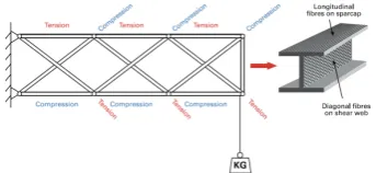
2.39 Internal structure described in I-beam (Burton et al. 2011) . . . . 76
2.40 Shearing and reinforcement of a simple frame concept (Burton et al. 2011) . . . 78
2.41 Extended framework with shear reinforcement (Burton et al. 2011) 79
2.42 Blade bending phenomenon (Burton et al. 2011) . . . 83
2.43 Power coefficient curves for the three different wind turbine types (Sandra et al. 2008) . . . 84
2.44 Growth of commercial wind technology (EWEA 2009) . . . 85
2.45 Example of ply drop off in composite materials (Trethewey et al. 1990) 86
2.46 Material specimen preparation (Cairns et al. 1997) . . . 87
2.47 Illustration of the structural model of a three-bladed free body diagram (Larsen et al. 2004) . . . 88
2.48 Illustration of pitch moment contributions from blade loads in the deflected location (Larsen et al. 2004) . . . 88
2.49 Modern wind turbine blade assembly (Petersen & Davis 2011) . . 90
2.50 Conceptual design of plate-like structure (Petersen & Davis 2011) 91
2.51 A cross section of a GFRP blade. The blade stretched over a composite frame (light grey) and central spar (yellow and green) (Petersen & Davis 2011) . . . 91
LIST OF FIGURES xix
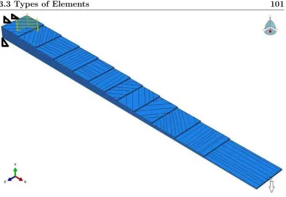
3.2 Suspended SMA of 1 wire and the GFRP which have undergone a
meshing process . . . 98
3.3 Graphical model representation with plies configuration orientation 101 3.4 Differences between conventional and continuum shell elements (Simulia 2012) . . . 102
3.5 MPC implemented between the SMA wires and the GFRP plate (end section view) . . . 104
3.6 Sketching part of the plate . . . 105
3.7 Sketching part of the wire . . . 106
3.8 The orientation of the angle between the SMA wire and the GFRP plate in the side view angle . . . 106
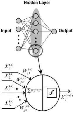
3.9 Biological diagram of a neuron . . . 108
3.10 Artificial neuron diagram . . . 111
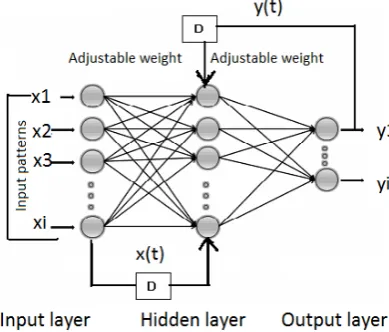
3.11 Graphical representation of the MBP network . . . 114
3.12 Graphical representation of NARX network . . . 115
4.1 Photograph of specimen preparation . . . 118
4.2 Photograph of DSC test equipment and the SMA specimen used . 121 4.3 DSC curve for 0.50 mm diameter NiTi . . . 122
4.4 Photograph of the calibration setup for SMA . . . 123
LIST OF FIGURES xx
4.6 Schematic operating principle . . . 126
4.7 Schematic diagram of SMA wires arrangement . . . 126
4.8 Photograph of experimental setup and values reading of the power supply in series mode driven when is current is activated (insert picture) . . . 127
4.9 Photograph of the tip deflection (a) before heating (b) after heating (section view) . . . 127
4.10 Schematic diagram of the experimental setup . . . 128
5.1 Tensile test setup with measurement of longitudinal and transverse strains by a contact extensometer . . . 131
5.2 Stress-strain response as a function of temperature for the SMA wire. All tests were performed on as-received. . . 132
5.3 Calibration test curve . . . 133
5.4 Calibration test and heat sleeve/non-heat sleeve test . . . 134
5.5 Load test of 0.5 mm SMA between relaxation and contraction . . 135
5.6 Load-deflection curves for Flexinol 90 . . . 136
5.7 Graphical model representation with part of the assembly layout . 137
5.8 Graded beam specimen representing plies drop off imitation . . . 137
5.9 Graphical model representation with number of plies configuration (top view) . . . 138
LIST OF FIGURES xxi
5.11 Comparison of vertical deflection of GFRP (with EPS/without EPS) between FEA and experiment . . . 139
5.12 Deflection contour S4R of the GFRP plate . . . 140
5.13 Deflection contour of SC8R of the GFRP plate . . . 141
5.14 Schematic diagram representation for model ANN 1 . . . 144
5.15 Example of NARX network with 10 hidden layers and 2 delay time by MATLAB . . . 145
5.16 Example of MBP diagram network with 50-40 hidden layers . . . 145
5.17 Best performance curve for ANN 1 . . . 146
5.18 The networks performance for ANN 1 . . . 147
5.19 Error histogram of the NARX prediction model for ANN 1 . . . . 148
5.20 Response of NARX model for output deflection for ANN 1 by MATLABR . . . 149
5.21 The deflection output and network output for ANN 1 by MBP . . 149
5.22 Schematic diagram for model ANN 2 . . . 150
5.23 Best performance curve for ANN 2 . . . 151
5.24 Error histogram of the NARX prediction model for ANN 2 . . . . 152
5.25 The networks performance for ANN 2 . . . 153
5.26 NARX prediction model for performance for ANN 2 . . . 153
LIST OF FIGURES xxii
5.28 Best performance curve for ANN 3 . . . 155
5.29 Error histogram of the NARX prediction model for ANN 3 . . . . 156
5.30 The regression analysis for ANN 3 . . . 157
5.31 Response of the NARX prediction model for performance for ANN 3158
5.32 Schematic ply configuration of the actual blade . . . 159
5.33 Embedded SMA fabrication . . . 160
5.34 Schematic diagram of embeded SMA wires . . . 162
5.35 Photograph preliminary study setup for embedded SMA and sus-pended SMA . . . 163
5.36 Heating and cooling curves of the SMA mechanism design . . . . 164
5.37 Photograph of the specimen embedded SMA wires fabrication . . 165
5.38 Photograph showing that delamination occurred along the embed-ded SMA wires . . . 166
5.39 Photograph of preliminary suspended SMA wires . . . 167
5.40 Comparison of suspended SMA wires under deflection testing with different numbers of SMA wires at specific heights . . . 168
5.41 Response time of suspended wire . . . 169
5.42 Tips deflection with different number of SMA wires under variable load at specific height . . . 170
LIST OF FIGURES xxiii
5.44 Simulation of smart wind blade model . . . 173
5.45 Calibration of the smart wind blade model under deflection . . . . 174
5.46 Tip deflection against current at different anchoring heights . . . . 176
5.47 Tip deflection against current at various load at 30 mm height, respectively . . . 178
5.48 Tip deflection against current at different number of SMA Wires . 180
5.49 Effect of heat sleeving and without heat sleeving at s1=366.8 g, s2=460.1 g, s3=576.8 g, s4=716.3 g and s5=1016.7 g for 2 SMA wire182
5.50 Deflection and alleviation response of the smart blade . . . 183
5.51 Simulation of the smart blade under deformation and stress recovery184
5.52 Stress of the blade under deflection for 1000 mm . . . 185
5.53 Strain under deflection - the blade under deflection for 1000 mm . 186
5.54 Voltage and current curve for 1000 mm specimen . . . 187
5.55 Deflection curve for 1000 mm specimen . . . 187
5.56 Voltage and current curve for 1000 mm specimen . . . 188
5.57 Cp- λ performance curve for a modern three-blade turbine . . . . 191
J.1 Tip deflection against current at various load at 40 mm height, respectively . . . 257
LIST OF FIGURES xxiv
J.3 Tip deflection against current at various load at 60 mm height, respectively. . . 259
K.1 Effect of heat sleeving and without heat sleeving at s1=366.8 g, s2=460.1 g, s3=576.8 g, s4=716.3 g and s5=1016.7 g for 6 SMA wire260
List of Tables
2.1 Summarise of modern and historical wind turbine designs (Peter & Richard 2012) . . . 24
2.2 Analysis methods of HAWT performance . . . 53
2.3 Theoretical Annual Specific Yield of HAWTs and VAWTs (Malcolm 2003) . . . 85
3.1 Laminate configurations . . . 99
3.2 Mechanical properties of SMA, GFRP, Epoxy and Core . . . 100
4.1 Transformation temperature of SMA . . . 122
5.1 Four parts of graded beam assembly . . . 131
5.2 Comparison of FEA and experimental work without SMA for vali-dation . . . 141
5.3 Prediction of the deflection with respect to the number of SMA wires using various models . . . 146
LIST OF TABLES xxvi
5.5 The results of the NARX model training for ANN 2 . . . 151
5.6 The results of the NARX model training for ANN 3 . . . 155
5.7 Plies configuration of the plate . . . 159
5.8 Gradient response for suspended wire . . . 172
5.9 Deflection d, reading values for 6 SMA wires at 1000 mm, 60 mm anchoring height . . . 184
5.10 Optimised values of the curve equations presented in Equation 5.5 (Slootweg et al. 2003) . . . 190
B.1 Tensile test for part 1 : 4 plies . . . 226
B.2 Tensile test for part 2 : 8 plies . . . 226
Notation
α angle of attack, ◦
θ angle of twist, ◦
υ Poison ratio
σ stress, Pa Γ vortex strength
WA resultant velocity, ms−1
r radius of the blade section considered, m Ω rotational speed of the turbine, rads−1 U0 velocity of the wind at tip, ms−1 λ tip speed ratio
ρ density of air, kgm−3 Cp coefficient of power
4A small portion area of a wind turbine blade
LA lift force, N
V wind velocity,ms−1 at.wt. atomic weight As austenite start, ◦C
Notation xxviii
Ms martensite start, ◦C
Mf martensite finish, ◦C
Acfunc. active functional
εym martensite twin strain
εd
m martensite detwin strain
εym martensite twin strain
εd
m martensite detwin strain
E Young’s Modulus, MPa
Em,t Young’s Modulus twin, MPa
Em,d Young’s Modulus detwin, MPa
∆ percentage difference, %
W width, mm
D depth, mm
H height, mm
NW number of SMA wires L applied load, N I applied current, Amp
N line of vortices d deflection, mm V voltage, V
w power, W
Acronyms and Abbreviations
ANN artificial neural network AuCd Aurum Cadmium AuCu Aurum Copper
BET Blade Element Theory CAD computer aided design CAE computer aided engineering
CEEFC Centre of Excellence Engineered in Fibre Composite CuZn Copper Zinc
EPS expanded polystyrene
EWEA European Wind Energy Association FEA finite element analysis
GFRP glass fibre-reinforced polymer GUI graphical user interface HAWT horizontal axis wind turbine
IGES initial graphics exchange specification LM Lavenberg-Marquardt
LVDT linear variable differential transformer MATLAB Matrix Laboratory
Acronyms & Abbreviations xxx
MLP multi-layer perceptron MSE mean square error
NARX Non-linear autoregressive with Exogenous NiTi Nickel Titanium
NACA National Advisory Committee for Aeronautics Nitinol Nickel Titanium Ordnance Laboratory
NREL National Renewable Energy Laboratory N/A not applicable
PPE personal protective equipment PVC Polyvinyl Chloride
R correlation coefficient factor SMA shape memory alloy
SME shape memory effect SE superelasticity TSR tip speed ratio
USQ University of Southern Queensland UPM Universiti Putra Malaysia
UD unidirectional
Chapter 1
Introduction
Meeting the world’s growing energy demands in line with preserving the envi-ronment has led to great progress in the field of renewable energy or so-called green energy. According to the Environmental Impact Assessment International Energy Outlook, the global energy demand is expected to almost double by 2030. Population and income growth are the key drivers behind the growing demand for energy (BP Energy outlook 20302013).
Renewable energy generation in Australia has been supported by a range of measures to assist in the research and development of new technologies and the deployment of newly commercialised technologies. The main support measure driving the deployment is the Renewable Energy Target (RET) Scheme.
2
Figure 1.1 depicts the Australian RET scheme. The enhanced RET scheme commenced on 1 January 2010 and was projected to deliver more than 45,000 gigawatt hours of electricity in 2020. It is expected to cost more than AUD$ 20 billion in investment over the next decade (ACEC 2012b).
Figure 1.1: Australian Renewable Energy Target: 20 % by 2020 (ACEC 2012b)
Figure 1.2: Renewable capacity installed since 2001 (ACEC 2012a)
1.1 Background and Significance 3
(PV) systems which accounted for approximately 20% and 29 % , respectively. Biomass capacity comprised approximately 6 %, and new hydroelectric capacity (mainly from upgrades to existing systems) also comprised approximately 6 % of the installed capacity. Wind energy, which has been considered as lower cost, has been the dominant large scale technology under the RET with nearly 2,200 MW of wind farms developed (ACEC 2012a). This significant deployment has resulted in technological developments, including an increase in capacity and an improvement in accessibility.
1.1
Background and Significance
Nowadays, wind power technology is not new in any fundamental way, but rather the rediscovery and development of a technology with considerable heritage. It was initially ignored since the world went through the era of industrialisation. It has been proven in the past that it was used to capture the wind in order to generate power. Historically, wind energy has been utilised for at least 30 centuries, mainly for agricultural purposes. In naval transportation services, the wind has been an essential source of power. Wind energy was once an integral part of rural activities and became almost obsolete with the advent of low-cost fossil-fuelled stationary engines, and then the spread of rural electrification (Musgrove 2010).
The rotor of the wind turbine needs some sort of aerodynamic profile device, e.g., a wing or turbine blade with an aerodynamic shape, to be able to rotate. As expected, the density of the air is less than water density, and this leads to the large size of a wind turbine. Ultimately, the blade radius reflects the efficiency of the operational wind turbine in an attempt to capture as much wind as possible (Griffth & Ashwill 2011, Jensen et al. 2006).
1.2 Problem Statement 4
a British aeronautical pioneer in 1915, and has been extensively reviewed by Albert Betz, a German aerodynamicist, in 1919 based on the well-known actuator disc theory (Eggleston & Stoddard 1987). The power coefficient of a rotor varies with the tip speed ratio and is only a maximum for a unique tip speed ratio. Incremental improvements in the power coefficient are continually being sought by detailed design changes of the rotor and by operating at variable speed it is possible to maintain the maximum power coefficient over a range of wind speeds. However, these measures will give only a modest increase in power output. Major increases in the output power can only be achieved by increasing the swept area of the rotor or by locating the wind turbines on sites with higher wind speeds.
The big argument for a size limit for wind turbines is based on the square-cube law which has been debated for a long time. The square-cube law, an idea first mentioned by Galileo (1638) in his publication entitled, “Discourses and Mathematical Demonstrations Relating to Two New Sciences,” practically this concept may relate to the physical and engineering basis with economies of scale. It is stated that as a wind turbine rotor increases in size, its energy output increases as the rotor-swept area (the diameter squared), while the volume of material, and therefore its mass and cost, increases as the cube of the diameter (Burton et al. 2011). In other words, at some size the cost for a larger turbine will grow faster than the resulting energy output revenue, making scaling a losing economic game. Therefore, many researchers have tried to exploit the square-cube law by changing the design rules with increasing size and removing material or by using material more efficiently either using new material or advanced material to trim weight and cost.
1.2
Problem Statement
1.2 Problem Statement 5
rotational motions for electrical generation. The importance of the turbine blade is such that an increase in the turbine blades efficiency would potentially result in an increase in the wind turbine efficiency as well. Efforts to increase the efficiency of the turbine blade are complicated by the combination of the varying aerodynamic effects acting on the blades and the structural stresses on the blades due to its shape. The shape of the turbine blades becomes increasingly important given the tendency of current blade design to be longer and thinner than past blade designs. Analysis of turbine blades is typically carried out using the actuator disk theory, an idealised model of the usable wind energy flowing over the turbine blades which will never be realised in the real operation of wind turbines. Based on the theory, it is impossible to extract more than 59 % of the useable amount of wind energy under ideal conditions. Previous studies of wind turbine performance utilised blade element theory in conjunction with actuator disk theory to predict the wind turbine blade performance. However, significant hurdles remain, especially when attempting to optimise the performance of wind turbine blades made from composite materials.
1.3 Objectives of the Project 6
would allow for thinner and longer turbine blade designs to be utilised. One promising area of research is the incorporation of Shape Memory Alloys (SMA) in the turbine blades, which are used as actuators to resist flapwise bending of the blades. The incorporation of SMAs in the turbine blade would pave the way for a new generation of thinner and more lightweight wind turbine blades that are able to better resist flapwise loads.
To determine the feasibility of incorporating SMAs as actuators to resist flapwise bending in turbine blades, a proof of concept experiment and associated Finite Element Analysis (FEA) and Artificial Neural Network (ANN) modelling were carried out in this project. Since the most important physical phenomenon under consideration is bending, the current work has assumed for simplicity, without any loss of generalisation, that the turbine blade can be modelled as a plate-like structure subjected to deflection. SMAs are then placed in different configurations on the beam to resist the bending deflection. The results are analysed, and used to verify and refine the FEA model.
1.3
Objectives of the Project
The steps taken here are to use SMA on an existing turbine blade with bending and deflection recovery action which can at least return the blade to its original form. Designing an entire smart turbine blade is not the output of the work here. The current research is primarily concerned with an innovation involving the development of a component which can be used in a thin reinforced composite wind blade turbine which is capable of maintaining performance and addressing the bending and deflection issue.
1.4 Research Gap and Innovation 7
Associated models have been identified for the purpose of the implementation of the system as a whole. In this context, the plate-like structure model is seen to have the same features in common which are relevant to the pilot study. Towards achieving the main objective, the related aims associated are identified as follows:
(i) To determine the feasibility of using SMA wires as an actuator for a smart wind turbine blade concept to reduce flapping;
(ii) To model the smart wind turbine blade concept as a plate-like structure to allow the performance parameters to be analysed.
1.4
Research Gap and Innovation
The main objective of this project is to develop the potential of smart mate-rial application in composites for wind turbine blades, based on the plate-like structure that can alleviate or release the composite stress upon deflection by self-straightening the blade to be as close as possible to its original shape. Ultimately, the goal is to evaluate the structural analysis and incorporate it into a conceptual design which can be further enhanced for a new generation of smart blades.
Due to the limited scope of this study, it was not possible to manufacture the full scale of the actual wind turbine blade. Thus, a conceptual design prototype that imitates the principle of the beam structure has been implemented based on the cantilever plate using a plate-like structure.
Finite element analysis was used as a tool to optimise the analysis before com-mencing the experimental work. Simulation in FEA using ABAQUS 6.12R has been developed to imitate the model as close as possible for purpose of analysis.
1.4 Research Gap and Innovation 8
the parameters’ data that was collected has been simulated to see the relationship correlation between the input and output values.
The result prediction of the work has been simulated using an ANN approach through using the NARX tool to predict the material and structural analysis response to deflection loading. Methods of obtaining data, such as the applied electrical current and the number of SMA wires, are also discussed. The informa-tion presented in this study will assist in the design of smart wind turbine blade composite structures for optimum efficiency and to combat fatigue, though it will be necessary to characterise the material combination and manufacturing process used at the detailed design stage.
Finally, structural analysis has been performed to quantify whether the expected desired outcome meets the actual operating condition. The expected outcome from this research is to manufacture new generation small smart blades which can overcome the operational distortions to the airfoil shape and the structural and property degradations of material that causes the loss of output energy of the wind turbine.
The innovations introduced are as follows:
(i) Use of SMA to minimise deflection and increase the lifetime of the blade;
(ii) Reduced deflections, which increase the power output and decrease the losses;
1.5 Organisation of the Thesis 9
1.5
Organisation of the Thesis
This thesis report is organised into six chapters which are as follows:
Chapter 1: begins with some general background, the problem statement, sig-nificance, objectives and expected outcomes;
Chapter 2: addresses the literature review regarding the analysis of wind turbine blade performance, the use of SMA, and the proposed concept of the smart wind turbine blade;
Chapter 3: discusses the FEA model and the ANN model development;
Chapter 4: describes the experimental setup;
Chapter 5: analyses the results and provides a discussion;
Chapter 6: provides some conclusions and gives recommendations for further work.
1.5 Organisation of the Thesis 10
Figure 1.3 depicts the flow of the project. The flow is divided into two categories which are the current approach and the innovative approach.
Chapter 2
Literature Review
2.1
Introduction
In order to understand, and place the research area into perspective, a rigorous study has been undertaken. A selection of relevant papers is reviewed. This investigation served as a basis and starting point for several decisions made during the research project. This chapter reviews the working mechanisms of the wind turbine such as aerodynamics, the development of the wind turbine, wind turbine blade construction, and the challenges and future direction of wind turbines. Next, the proposed conceptual model has also been discussed. A summary of this review chapter is presented in the final section, highlighting the research direction of the current thesis.
2.1.1
History of Wind Turbines
2.1 Introduction 12
Although today’s modern technology has firmly, and maturely, established the description of a wind turbine as the prime mover of a wind machine capable of being harnessed for a number of different applications, none of which are concerned with the milling of grain or other substances (at least in industrialised countries), the term windmill was used for the whole system up to recent times, whatever its duty, be it generating electricity, pumping water, or sawing wood. Since here the historical development of the wind machine is considered, it is convenient and has a certain logic in it to retain its term, i.e. windmill in its historic sense (Nelson 2009). However, this lies in the fact that the vertical-axis Persian windmills never came into use in Europe. At the end of the twelfth century, there was an emergence of a completely different type - a horizontal-axis windmill. This development presents the future generation in the technical development of the wind turbine, which has existed several thousands years since the invention left by the Persian vertical-axis windmills (Spera 2009).
Before the invention of the European countries, horizontal-axis windmills were designed by Ebullz (1153) from Artuk Turks and were used in the region of Di-yarbakir in the 1200’s. However, Northwest Europe, particularly the Netherlands, France, Germany and Great Britain are considered to be the first regions that developed the most effective type of windmill, one in which the shaft carrying the sails was oriented horizontally rather than vertically as in the Persian mill. In a relatively short time, tens of thousands of the so called horizontal-axis European windmills were in use for nearly all mechanical tasks, including water pumping, grinding grain, sawing wood and powering tools. The cruciform pattern of their sails prevailed for almost 800 years, from the twelfth to the twentieth century (Spera 2009).
2.1 Introduction 13
into the wind, and stopping the rotor when necessary. But the adoption of the horizontal-axis windmill is readily explained by the fact that it was so much more efficient (Harrison et al. 2000).
In the historical development of windmills, a very innovative step that warrants somewhat more attention than it has received, must be considered: the use of horizontal-axis windmills instead of vertical-axis ones. Although the right angle gear mechanism allowed the rotor axis to be transposed from vertical to horizontal, the action of the sails also had to be turned through 90◦.
This was revolutionary because it meant that a simple, straightforward push of the wind on the face of the sail was replaced by the action of the wind in flowing smoothly around the sail, providing a force normal to the direction of the wind. As a concept, it is a sophisticated one that was not fully developed until the advent of the airplane at the end of the 19th century, and the engineering science of aerodynamics (Manwell et al. 2009).
An innovative type of wind turbine rotor, the Savonius rotor, was named after its inventor, the Finnish engineer S.J. Savonius. This is illustrated in Figure 2.1. The inventor’s interest had been aroused by the Flettner rotor ship with its large, rotating cylindrical sails. Wind passing over these cylinders created lift by the Magnus effect, which propelled the ship forward. He was intrigued by the possibility of substituting wind power for the external motor power used to rotate these cylinders on the Flettner ship. His experiments resulted in a rotor with an S-shaped cross section which, in its simplest form, could be constructed by cutting a circular cylinder in half longitudinally and rejoining the opposite edges along an axle. Different types of turbine are given in Figure 2.1.
2.1 Introduction 14
Figure 2.1: Types of wind turbine - from left, Savonius, Darrieus and H-Rotor (Sandra et al. 2008)
upper and lower bearings, and transmits torque from the blades to the power train, which is located below the rotor, where the maintenance is easier, and the weight is not quite so important (Sandra et al. 2008).
The transition from windmills supplying mechanical power to wind turbines producing electrical energy took place during the last 12 years of the 19th century.
The initial use of wind for electric generation, as opposed to mechanical power, included the successful commercial development of small wind generator research, and experiments using large turbines. The advent, and development of the airplane in the first decades of the 20th century gave rise to deep analysis, and design
studies of the propeller, which could immediately be applied to the wind turbine (Manwell et al. 2009).
The primary application of wind turbines is to generate energy from the wind. Hence, aerodynamics is a very important aspect in the design of wind turbine blades. The aerodynamic profiles of wind turbine blades have a vital impact on the aerodynamic efficiency of a wind turbine.
2.2 Wind Turbine Blade Geometry 15
apply to all turbines. Every blade profile has a maximum power for a given flow, and some shapes are better than others. The method used to extract power has a strong influence on this. In general all turbines can be grouped as being lift-based, or drag-based with the former being more efficient. The difference between these groups is the aerodynamic force that is used to extract the energy.
The most commonly used turbine blades are in the horizontal-axis wind turbine. The blades generate a high lift force resulting in very good performance. Ac-cordingly, it is popular for commercial applications, and much research has been applied to this turbine. Towards the 20th century the Darrieus wind turbine was
another popular lift-based alternative, but is rarely used today. In principle, the Savonius wind turbine operates based on a drag mechanism, and despite its low efficiency, it is used because it is robust and simple to build and maintain.
As discussed earlier, a wind turbine is a device that converts the power of the wind into electricity. This is in contrast to a windmill, which is a machine that converts the wind’s power into mechanical power. It generally does this by using the basic aerodynamic force of drag to produce a net positive torque on a rotating shaft, resulting in the production of mechanical power. There are two great classes of wind turbines, horizontal and vertical axis wind turbines. Conventional wind turbines, horizontal-axis wind turbines (HAWT), rotate about a horizontal axis. As the name implies, a vertical-axis wind turbine (VAWT) rotates about a vertical axis.
2.2
Wind Turbine Blade Geometry
2.2 Wind Turbine Blade Geometry 16
structural capability. Led by Case van Dam of UC Davis, the team performed a systematic investigation into the use of a series of inboard airfoils whose thickness and trailing-edge flap could be adjusted independently to give a constant thickness for the spar cap and trailing-edge spline. This series of airfoils was developed from high-lift inboard NREL airfoils, and the LS-1 series airfoils. Representative inboard section shapes are shown in Figure 2.2a and are labeled as flatback airfoils to denote the lift-enhancing trailing edge flat.
(a) Flatback airfoils (Dam et al. 2005) (b)CL for flatback and traditional
airfoils (Dam et al. 2005)
Figure 2.2: Flatback development
Figure 2.2b illustrates the comparison of the coefficient of lift, CL between the
flatback compared to the traditional type of airfoil. These airfoils have the potential for decreasing coefficient because the thicker sections allow for a lighter blade (higher moment of inertia) and increased lift characteristics could allow for enhanced performance. However, the drag is also increased, and it is expected that trailing edge treatment, such as splitter plates, may be required to reduce the increased drag.
2.2 Wind Turbine Blade Geometry 17
Straub (1996) where all the available concepts were analysed, particularly the control concept; pitch control, twist control, camber control and a movable con-trol device (trailing edge flaps or servo tabs actuated by smart materials) are recommended. A 1.83 m diameter scaled wind turbine smart tip wind turbine blade actuated with a piezo-induced bending-torsion couple composite beam has been developed by Chopra (2002). This showed potential control suppression vibration due to flapping deflection. Furthermore, Chopra (2002) investigated the use of SMA in a blade section model with tabs actuated by SMA wires. He demonstrated that the performance was good in terms of deflection.
The most recent in active control smart devices is that of the ADASYS project (a joint venture task between Eurocopter, EADS CRC, Daimler Chrysler Research Labs and DLR) (Enekl et al. 2002, Roth et al. 2006)
An actively actuator full-scale rotor was developed based on a BK117/EC145 utilising controlled piezoelectric actuated trailing edge flaps (Figure 2.3a, 2.3b). The system was tested during flight and showed excellent performance in reducing vibratory loads by 50–90 %.
(a) Layout of the piezoelectric
actuated developed in ADASYS
(Enekl et al. 2002)
(b) Actively controlled
piezoelectric actuated on the
BK117 blade (Roth et al. 2006)
Figure 2.3: Controlling smart blades using piezoelectric
2.2 Wind Turbine Blade Geometry 18
large leverage near the blade tip) for the reduction of blade root moments, without using full blade pitching, which is inefficient due to the use of the swashplate and the larger inertia.
Furthermore, a significant attempt was made to use embedded actuation on the blades which resulted in shape morphing (camber control) or twisting (active twist) as shown in Figure 2.4a. A prototype profile section of 2 m was mounted with 36 piezoelectric actuators at 10 % chord length. The idea comes from the Gurney flap in which active control microtabs were used. Microtabs are small (deployment height in the order of the boundary layer thickness) translational
devices placed near the trailing edge of the airfoil as illustrated in Figure 2.4.
2.2 Wind Turbine Blade Geometry 19
(a) Thunder piezoelectric actuator
(b) Performance curve using microtab
(c) Microtab concept
2.3 Modern Wind Turbines 20
Other developments are shown in Figure 2.5, which include bend-twist coupling, aileron, changing shape and microtab.
(a) Bend-twist (b) Aileron
(c) Airfoil with changing shape (d) Microtab
Figure 2.5: Bend-twist coupling, aileron, changing shape and microtab (Barlas & Kuik 2007)
2.3
Modern Wind Turbines
Wind turbine technology, inactive for many years, awoke at the end of the 20th
2.3 Modern Wind Turbines 21
composites for the blades and alloys for the metal components. Developments in computer technologies facilitate design, analysis, monitoring and control. Aero-dynamics design methods, originally developed for the aerospace industry, have now been adapted to wind turbines (Eggleston & Stoddard 1987). Analytical methods have now developed to the point where it is possible to have a much clearer understanding of how the new design should perform than was previously possible. Testing using a vast array of commercially available sensors and data collection and analysis equipment allows designers to understand how the new turbines actually perform. Power electronics is a relatively new area which is just beginning to be used with wind turbines. Power electronic devices can control the turbine’s generator smoothly which plays a crucial role in the electrical network: allowing the turbine to run at variable speed, producing more energy, reducing fatigue damage, and benefiting the utility in the process; facilitating operation in a small, isolated network; and transferring energy to and from storage.
Materials such as fibre-reinforced composites are becoming an attractive option in the wind turbine blade industry in recent years due to their several advantages such as their high strength and light weight. Furthermore, composite structures have been used widely in industry, such as in the aerospace, marine and automotive field, and they have now transitioned to become viable materials for other applications such as mechanical structures, particularly for lightweight structural applications. One major area for the lightweight structure is wind turbine blades (Eker et al. 2006).
2.4 Identification of Parameters for Efficiency Improvements 22
or flexibility where it is most needed. Fibre composites are used to manufacture high-performing products and components.
Wind turbine blades are usually made in polymer matrix composites, often glued together. Such structures may lead to a number of possible failure modes. For example, cyclic loading that can ultimately results in wind turbine blades failure. Wind turbine are subjected to fluctuating wind and hence flapwise bending are acting on the blades. Components, which are subject to repeated axial bending, such as wind turbine blades, may eventually develop cracks, which ultimately may make the component, break. Therefore, failure of wind turbine blade could be a big catastrophic if there is no immediate solution for safety measures which has not been taken into consideration.
2.4
Identification of Parameters for Efficiency
Improvements
In practice, wind turbine designs suffer from the accumulation of minor losses resulting from tip losses, wake effects, drive train efficiency losses and blade shape simplification losses.
2.4 Identification of Parameters for Efficiency Improvements 23
Dutch windmill is another example of an early lift type device utilised for grinding corn which has now disappeared from mainstream use, yet a small number still survive as tourist attractions. The Darrieus VAWT is a modern aerodynamic aerofoil blade design which despite extensive research and development has so far been unable to compete with the modern HAWT design. However, recent developments could see a resurgence of this rotor type. Due to its efficiency and ease of control, the aerofoil three bladed HAWT has become the wind turbine industry benchmark, with a fully established international supply chain securing its dominance for the foreseeable future.
2.5 Smart Materials 25
2.5
Smart Materials
As Fibre Reinforced Plastic (FRP) Composites become well-established and have been widely used in the modern wind turbine blade, more ideas arise on how best to combine different materials to enhance a variety of structural properties. The development of smart materials, such as piezoelectric materials (PZT), shape memory alloys (SMAs) and electroactive polymers, have given more spaces for the creation of smart composites (Leo 2007). Smart materials, also referred to as active/functional/intelligent materials, exhibit coupling between the mechanical field and some other physical field (thermal, electric, magnetic etc.), and thus a stimulus in one of the fields provokes a response in the coupled field. This coupling can be exploited for sensing and/or actuation as shown in Figure 2.6.
Figure 2.6: Various types of mechanism for smart materials (Leo 2007)
In sensing, a stimulus in the mechanical field provokes a response in the coupled field which can be measured, while, in actuation, the coupled field is used to provoke a mechanical response. The composite itself can exhibit smart-like properties, by embedding a smart material in the composite. Smart materials can be used for many purposes, the main idea being to control and adapt the structural properties according to a change in external conditions.
2.6 Shape Memory Alloy (SMA) 26
complexity of the problem and, in many cases, introducing sources of non-linearity. Moreover, in some cases the mechanisms underlying the coupled behaviour are still not fully understood, thus further investigation of the active material itself is required prior to considering the composite.
Finally, for many smart materials of recent conception, not much information is available regarding their long-term behaviour, such as their fatigue life and the stability of the response with increasing numbers of cycles. All the stated difficulties make active composites a very challenging yet promising topic for researchers, which involves many different disciplines (chemistry, material science, structural engineering etc.) working together to achieve structural performances which would have been impossible with traditional materials.
2.6
Shape Memory Alloy (SMA)
For centuries, metals have played a pivotal role as structural materials in engi-neering applications. Advances in material sciences over the past decade have led to the ability to develop materials, be they alloys or composites, which exhibit a multiplicity of physical properties, each tailored for a variety of applications. In a number of industries, it has become crucial to produce lighter, stronger materials that address rigorous structural requirements, and provide scientific functionality. Materials are being developed based on the core principles of physics, and one of the most prolific and most interesting classes of smart materials is the shape memory alloy (SMA). This group of materials is attracting considerable attention amongst scientists across the world and is one of the largest growing areas of research today.
2.6 Shape Memory Alloy (SMA) 27
have banded regions of differently orientated microcrystalline phases, compared to substandard steels which were found to have little coherent patterning. Martens discovered that steels undergo a structural phase transition. At low temperatures steels are body-centred cubic (BCC) and face-centred cubic (FCC) at high tem-peratures, forming martensites. This structural phase transition was named after him (Portella 2006).
This contribution to the innovation of shape memory alloys was until this point unnoticed. Wayman & Otsuka (1999) claimed that the first clear progression towards the discovery of the shape memory effect was developed in the 1930s . A Swedish Physicist named Arne Olander revealed, whilst examining the AuCd system, that a deformed AuCu alloy could return to its original shape when the material was heated above some critical temperature (Smith 2005). In 1938, Greninger & Mooradian (1938) observed the appearance and disappearance of martensitic phases in CuZn as a function of temperature, making this transition between states completely temperature dependent. However, it was not until a decade later that Kurdjumov & Khandros (1949) made the most important impact on the development of shape memory alloys. In 1949, the concept of the thermoelastic behaviour, (which is when both changes in stress and temperature alter the dimensions of an object), of the martensitic phase in AuCd, CuZn and CuAl alloys was put forward, explaining the reversible martensitic transformation based on experimental observations. Chang & Read (1951) used X-ray analysis to uncover some of the mechanisms in the AuCd system, confirming the thermoelastic behaviour of the martensite. By 1953, the presence of thermoelastic martensitic transformations was confirmed in several other systems such as NiTi and CuZn.
2.6 Shape Memory Alloy (SMA) 28
which was the invention for engineering applications of shape memory alloys. The discovery of NiTi was somewhat of an accident. Buehler et al. (1963) had investigated new materials for heat shielding when they noticed that aside from the samples good mechanical properties, comparable to most common engineering materials, the material also possessed a shape recovery capability.
The term Shape Memory Effect (SME) was given with respect to this shape recov-ery behaviour, which is due to the reversible martensitic transformation that the material possesses. The discovery of Nitinol contributes a large space of research into the development and refinement of Shape Memory Alloys (SMAs). For exam-ple, the effects of altering the composition, heat treatment and microstructure were thoroughly investigated, and more knowledge began to emerge from this work.
SMA is one of the exciting new technologies that offers many advantages and usages. Some of their best properties are their high force-to-weight ratio, incredibly small size and volume, as well as their low cost compared to conventional actuators. However, SMAs are not free from drawbacks such as the non-linearities and hysteresis that are present in the phase transitions, and also their limited strain and bandwidth. The potentials of SMAs and their feasibility for use in robotic or other commercial applications are still being explored.
As materials become more reliable and a deeper understanding is acquired about the mechanisms involved, technology which utilises specific properties becomes available. For decades, scientists and engineers alike have worked towards con-verting thermal energy into mechanical work. The first large-scale and most well-known application of SMAs according to Melton (1999) was their use as a coupling to connect hydraulic titanium tubing in the Grumman F-14 aircraft (Wayman & Harrison 1989).
2.6 Shape Memory Alloy (SMA) 29
engineers have looked to the unique properties of SMAs to solve daunting engi-neering problems. Space technology harnesses the most current ideas, theories and discoveries throughout all the science and engineering disciplines. Stoneham (1999) addresses some of the most promising applications for SMAs in the demanding environment of space technology and aeronautics. The implementation of SMA technology in the aerospace industry has spread across a variety of areas, such as fixed winged aircraft, rotary aircraft and spacecraft design. In 1995, the smart wing programme was developed by Kudva et al. (2002). In this development, SMA torque tubes were employed to modify the aerodynamic properties of an airfoil, which increases the lift.
Another remarkable effort to integrate SMAs into aerospace structures was a study presented by Strelec et al. (2003) which led to the development of a variable geometry airfoil. Due to the nature of SMAs, wires that have had sufficient training, begin to act as linear actuators. Generally, SMAs have unique characteristics and can remember their shape at both high and low temperatures.
With sufficient training, the system can be taught to remember the low temperature shape. This is accomplished by leaving traces of the deformed low temperature martensite in the high temperature phase. A study of the training processes was carried out by Perkins & Hodgson (1999) in detail. The most common methods of training involve: over-deformation while in the martensitic condition; shape memory cycling where the system is cooled, deformed, and then heated repeatedly; and training by pseudoelastic cycling where the system is loaded and unloaded. The study illustrated that by attaching SMA wire actuators to selected points on the inside of an aerofoil, its shape can be changed drastically thus improving the dynamics of flight.
2.6 Shape Memory Alloy (SMA) 30
eject disks from laptop computers, small microvalves and a host of other devices, all share a common material technology. The interesting behaviour of each of these devices relies upon a phenomenon called the shape memory effect that refers to the ability of a particular kind of alloy material to revert to, or remember, a previously memorised or preset shape.
In the advanced application of SMA so far, it has also been applied in aerospace technology for noise suppression. This new approach has demonstrated the feasibilty of SMAs may be used in reducing noise level. Figure 2.7a illustrates the current Boeing design for the variable geometry chevron. Note that the composite layer has been removed from the chevron for exposition of the active SMA elements. Figure 2.7b illustrates the results of current efforts to model the Boeing chevron system. Here, complex behaviours such as the elastic laminate response of the composite substrate, sliding contact, and 3D non-homogeneous SMA loading have all been considered (Hartl & Lagoudas 2007).
(a) Boeing variable geometry chevron,
flight testing
(b) Stress contour results from FEA
analysis of VGC, actuated position
Figure 2.7: Example SMA application in Variable Geometry Chevron (VGC) for Boeing 777 (Hartl & Lagoudas 2007)
2.6 Shape Memory Alloy (SMA) 31
gases to mix. One of the leading aircraft manufacturers Boeing has consequently introduced embedded SMA bar components into chevrons in aircraft engines. At low altitude flight or slow speeds, the SMA component is in its austenite phase, and the SMA chevrons can be bent into the stream of the outgases expelled by the engine. In doing so, this further increases the mixing of the outgases and further reduce noise. During high altitude flight, at higher speeds and a colder temperature, the SMA chevrons would transform into their martensite phase, straightening the chevrons forming a rigid body and boosting aircraft performance (Mabe et al. 2005).
In automotive applications, SMAs also have the ability to act as sensing devices, or as actuation and sensing devices simultaneously. An application that harnesses this ability is an SMA spring used in the variable transmission of the Mercedes Benz A-Class. The spring acting as a sensor, continuously monitors the temperature of the system, and at a specific temperature, actuates a valve, which redirects the flow of oil within the transmission (Duerig 1999). Shinkansen, which is also known as the Bullet train, is equipped with aluminium gearboxes that incorporate an automatic oil level adjusting system (valve). The valve with an SMA spring controls the oil level inside the gearbox according to the change of oil temperature which is shown in Figure 2.8. SMA springs in the automatic oil quantity adjustment unit inside the gear boxes sense the oil temperature. It will open and close automatically, and supply the optimum quantity of oil to the shaft bearings. This system helps lower electricity consumption during high-speed operation.
2.6 Shape Memory Alloy (SMA) 32
Another recent application used in the automotive industry has been implemented in Corvette cars, by the General Motors manufacturer, as shown in Figure 2.9. The SMA wire used in the new Corvette will open the hatch vent whenever the deck lid is opened, using heat from an electric current that works in a similar manner as the trunk lights. It replaces a heavier motorised part to open the vent. When activated, the wire contracts, and moves a lever arm to open the vent, allowing the trunk lid to close. Once the trunk lid is closed, the electric current switches off, allowing the wire to cool and return to its normal shape, which closes the vent to maintain cabin temperature (Auto 2013).
Figure 2.9: Corvette’s heat-activated smart material (Auto 2013)
2.7 Characterisation of SMA for Smart Wind Turbine Blades 33
2.7
Characterisation of SMA for Smart Wind
Turbine Blades
SMAs are defined by their remarkable ability to sustain and then recover large super elastic strains by stress and temperature dependent crystallographic trans-formations. SMAs have sensing and actuating functions and have the potential to control the mechanical properties and responses of their hosts due to their inherent unique characteristics of the shape memory effect (SME) and superelasticity (SE). When integrated into structural components, SMAs perform sensing, diagnosing, actuating and repair or healing functions, thereby enhancing the performance characteristics of their hosts (Armstrong & Lilholt 2000, Zhang et al. 2007).
Figure 2.10 shows a comparison of other rival materials acting as a function of actuation stress-strain. The actuation energy density (work output per unit mass) of SMAs is among the highest at this range and is denoted in Figure 2.10 by the dotted lines at 10 MJ/m3. The energy density is defined as the product of the actuation strain (related to the stroke of an actuator) and the actuation stress, assuming here that the active material is operating under constant stress. The specific actuation energy density for a specific active material can be calculated from Figure 2.10 by dividing the actuation energy density by the mass density. The range of the actuation lies between 4–10 % and the average maximum stress is between 100–1000 MPa with a density of 10 MJ/m3.
Smart materials can be tailored to create a specific response to a combination of inputs (Suleman 2001). These materials include piezoelectric, electrostrictive, magnetoresistive, and SMA. Combinations of SMAs exist such as magnetic SMA and shape memory polymers.
2.7 Characterisation of SMA for Smart Wind Turbine Blades 34
Figure 2.10: Actuation stress-strain of selected SMA (Lagoudas 2008)
They have a frequency between 0.1 to 20 Hz. However, piezoelectric was in the bottom level. The rest of the smart materials are a combination of piezoelectric polymer, SMA, magnetic and electrostrictive and are in the middle group.
Figure 2.11: Actuation frequency diagram of different active materials (Lagoudas 2008)
When dealing with the properties of SMA materials, they can be divided into two parts which are:
(i) the shape memory effect;
2.7 Characterisation of SMA for Smart Wind Turbine Blades 35
2.7.1
Shape Memory Alloy Behaviour
An SMA exhibits the shape memory effect (SME) when it is deformed while in the twinned martensitic phase and then unloaded while at a temperature below the Austenite start (As). When it is subsequently heated above the Austenite
finish (Af), the SMA will regain its original shape by transforming back into the
parent austenitic phase.
The phase of temperature of the SMA was used to set the working setting condition. It has been implemented by the heat treatment or annealing process. This phase of temperature was applied to guide the reference temperature for the development of the prototype in this study.
A heat treatment must be carried out in order to ensure that the material reaches the desired temperature which is required for a specific s