University of Southern Queensland
Faculty of Health, Engineering & Sciences
Remote Access Intravenous Pump Emulator
Training System
A dissertation submitted by
Jorja Wicks
In fulfilment of the requirements of
ENG4111 / ENG4112 Research Project
towards the degree of
i
Abstract
Remote Access Laboratory (RAL) based learning is fairly uncommon outside of engineering faculties. Although, due to an increasing number of online higher education alternatives dominating traditional on-campus education options, and the sheer number of nurses spread across Australia, nursing and midwifery disciplines present an additional candidate for remote access learning applications.
The project aim is to develop a remotely accessible IV pump emulator (IVPE) training system for nursing and midwifery students based on a web server enabled Human to Machine Interface (HMI) operator panel and a Programmable Logic Controller (PLC). This project extends from an IVPE designed in 2012 for a Baxter IV Pump. Since its development, the Baxter IVPE has been used in teaching and research; however, the Baxter IV pump is now no longer commonly used in Australian health facilities and teaching practices. This projects IVPE will be based on the CareFusion Alaris™ system that USQ’s School of Nursing and Midwifery is currently using for teaching IV administrations IVPE incorporates educational materials, a learning mode (guided) and an assessment mode (unguided) for user to learn easily and the test their skills on setting up the virtual pump and correctly programming the medication administration.
ii
University of Southern Queensland Faculty of Engineering, Health and Sciences
ENG4111 Engineering Research Project Part 1 & ENG4112 Engineering Research Project Part 2
Limitations of Use
The Council of the University of Southern Queensland, its Faculty of Engineering, Health and Sciences, and the staff of the University of Southern Queensland, does not accept any responsibility for the truth, accuracy or completeness of material contained within association with this dissertation.
Persons using all or any part of this material do so at their own risk, and not at the risk of the Council of the University of Southern Queensland, its faculty of Engineering, Health and Sciences or the staff of the University of Southern Queensland.
This dissertation reports an educational exercise and has no purpose of validity beyond this exercise. The sole purpose of the course pair entitled “Research Project” is to contribute to the overall education within the student’s chosen degree program. This document, the associated hardware, software, drawings and other material set out in the associated appendices should not be used for any other purpose: if they are used so, it is entirely the risk of the user.
Dean
iii
Certification of Dissertation
I certify that the ideas, designs and experimental work, results, analyses and conclusions set out in this dissertation are entirely my own effort, except where otherwise indicated and acknowledged.
I further certify that the work is original and has not been previously submitted for assessment in any other course or institution, except where specifically stated.
Jorja Wicks
Student Number: 0061032747
……….. Signature
iv
Acknowledgement
I wish to thank Mrs Catherine Hills for her ongoing supervision and guidance throughout this research project. The time and knowledge she has provided me has been invaluable to my project and I would like to genuinely thank her for her support and assistance.
I would also like to thank Dr Leslie Bowtell, Dr Victoria Terry and various USQ nursing staff for their assistance and expertise along the way.
v
Contents
Abstract ... i
Limitations of Use ... ii
Certification of Dissertation ...iii
Acknowledgement ... iv
List of Tables ... ix
List of Figures ... x
Nomenclature ... xiii
1. Introduction ... 1
1.1. Aim ... 1
1.2. Objectives ... 2
1.3. Motivation ... 3
1.4. Dissertation Overview ... 4
2. Background ... 5
2.1. CareFusion Alaris™ System ... 5
2.2. Registered Nurse and Midwives Statistics ... 7
2.3. Technology, education and nursing ... 8
2.4. Brief History of Industrial Automation ... 10
2.4.1. Introduction of Programmable Logic Controllers ... 11
2.4.2. Development of Human to Machine Interfacing ... 13
3. Literature Review... 17
vi
3.1.1. Pedagogical Aspects of Clinical Training ... 18
3.1.2. Current IV Training Methods ... 20
3.2. Medication Errors ... 21
3.2.1. General Medication Error Statistics ... 24
3.2.2. IV Specific Medication Administration Error Statistics ... 25
3.2.3. Medication Administration Error Prevention ... 27
3.3. Previous Work - Baxter IVPE ... 28
3.4. Learning with Information and Communications Technologies ... 32
3.4.1. Designing ICT tools for educational purposes ... 33
1.5.2. Remote Access Technologies in Education ... 34
4. Task Analysis & Project Methodology ... 35
4.1. Project Planning ... 35
4.2. Task Plan & Analysis ... 35
4.2.1. Design & Test Procedure ... 36
4.3. Resource Analysis... 38
4.3.1. PLC Specifications & Resources ... 39
4.3.2. HMI Specifications & Resources ... 41
4.3.3. Hardware & Communications Configuration Setup ... 43
4.4. Consequential Effects ... 45
4.5. Project Timeline ... 45
5. IVPE Initial Design Planning ... 46
5.1. Design Objectives ... 46
5.2. IVPE Page Structure & Navigation ... 46
vii
6. IVPE Software Development ... 50
6.1. Software Development Phases ... 50
6.2. Software Background... 52
6.3. Phase 1: HMI Foundations & Aesthetics ... 55
6.4. Phase 2: Main Program & Resource Page Development ... 57
6.4.1. Main program ... 57
6.4.2. Resources Page ... 59
6.5. Phase 3: Foundation HMI/PLC development ... 61
6.6. Phase 4: Separated Development of Learning, Assessment & Survey Screens ... 66
6.6.1. Learning Mode ... 66
6.6.2. Assessment Mode ... 68
6.6.3. Survey ... 69
6.7. Phase 5: Final Stages ... 71
6.7.1. Remote Access - Webserver Configuration ... 71
7. Results & Discussion ... 73
7.1. Technical & Non-technical Challenges ... 73
7.2. Achievement of Objectives ... 74
7.3. Overall System Evaluation ... 76
8. Conclusions & Further Work ... 77
References ... 79
Appendix A – Project Specification ... 85
Appendix B – Project Timeline ... 86
Appendix C – PLC Specifications ... 87
viii
Appendix E – Consequential Effects ... 93
4.4. Consequential Effects ... 93
4.4.1. Ethics ... 93
4.4.2. Risk Analysis, Evaluation & Control... 94
Appendix F – Ethics Consent Form (Over 18) ... 97
Appendix G – Engineers Australia Code of Ethics ... 98
Appendix H – IVPE ‘6 Rights’ Resources ... 99
Appendix I – IVPE Assessment Case Studies... 100
Appendix J – HMI PC & Pump Graphics Development ... 104
Appendix K – PLC Comm Ports setup ... 105
Appendix L – Data Tags & Memory Plan ... 106
Appendix M – Webserver Setup ... 108
ix
List of Tables
Table 1: Error categories, adapted from J.K Aronson (2009) ... 22
Table 2: IV administration error rates from international literature. ... 25
Table 3: Medication administration errors: Australian hospitals 1988-2007 (Roughead, Semple & Rosenfeld 2013) ... 25
Table 4: Required Resources and Approximated Costs ... 39
Table 5: Comparison of PLC types (Automation Direct 2016)... 40
Table 6: PLC to PC connection ports, cables and protocols ... 44
Table 7: PLC to HMI panel connection ports, cables and protocols ... 44
Table 8: Panel to PC connection ports, cables and protocols ... 44
x
List of Figures
Figure 1: CareFusion Alaris™ PC Unit with two pump modules (CareFusion 2016)
... 3
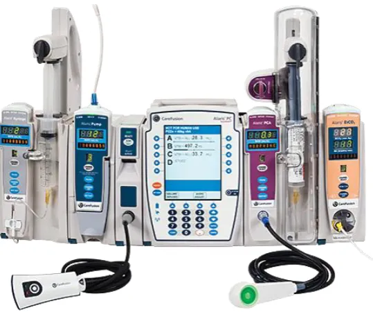
Figure 2: PC & five modules, left to right: Syringe, Pump, Auto-ID, PC, PCA (CareFusion 2016) ... 6
Figure 3: General registration by age group adapted from (NWBA 2016) (U-25 = under 25) ... 7
Figure 4: A range of smart HMI devices (Katzel 2012) ... 14
Figure 5: Example HMI screen of a plant process (Katzel 2012) ... 15
Figure 6: An example of a HMI Remote Access System (Automation Direct 2016) ... 15
Figure 7: Registered Nurse Standards (Nursing and Midwifery Board of Australia 2016) ... 18
Figure 8: Model of educational delivery and transition from learner to patient centred ... 19
Figure 9: Existing System (Real IV Pump - Left, Emulated Pump - Right) (Osbourne 2012) ... 29
Figure 10: Baxter IPVE Welcome Screen (Osbourne 2012) ... 30
Figure 11: Baxter IVPE Resource Page (Osbourne 2012) ... 30
Figure 12: Screen capture of Baxter IVPE during Assessment Mode ... 31
Figure 13: Learning activities categorised by two dimensions (Grabe & Grabe 2007) ... 33
Figure 14: CLICK Koyo C0-02DD2-D PLC (Automation Direct 2016) ... 39
Figure 15: C0-02DD2-D/C0-02DD1-D I/O, ports and indicators (Automation Direct 2016) ... 40
Figure 16: HMI C-more Touch Panels (Automation Direct 2016) ... 41
xi
Figure 18: Example Picture of a HMI project being developed (Automation Direct
2016) ... 43
Figure 19: Programming Cable RS232/USB (Automation Direct 2016) ... 44
Figure 20: IVPE Design Objectives adapted from (Terry 2015) and (Osbourne 2012) ... 46
Figure 21: IVPE Page Structure ... 47
Figure 22: Clinical Experiment Process Flowchart adapted from (Bowtell et al. 2012) ... 49
Figure 23: HMI Tag Database ... 52
Figure 24: HMI tag database export file format ... 53
Figure 25: PLC tag database export file format ... 53
Figure 26: A typical view of CLICK software ... 54
Figure 27: Basic System Data Flow Diagram adapted from (Osbourne 2012)... 55
Figure 28: IVPE Alaris Background Graphics (with tubing) ... 56
Figure 29: Background screen 1 (left) and Background screen 2 (right) ... 56
Figure 30: Welcome screen (left) and Home screen (right)... 57
Figure 31: Main Program with subroutine calls ... 58
Figure 32: Resources Page - Nursing Content ... 59
Figure 33: Incrementing with NEXT arrow and decrementing with PREV arrow ... 60
Figure 34: Resetting gallery integers if the gallery is closed ... 61
Figure 35: PC screen backgrounds in multistate bitmap ... 62
Figure 36: Inserting IV Set before programming channel ... 63
Figure 37: Control logic for 1st key press of RATE ... 64
Figure 38: Recreating pump status indicator lights ... 65
Figure 39: Warning Bubble ... 66
Figure 40: Small block of code demonstrating Hint 1 bubble ... 67
Figure 41: Four Screens within Learning Mode showing Orange Hint Bubbles ... 67
Figure 42: Learning Mode screen shots ... 68
xii
Figure 44: Incomplete Survey Page ... 70
Figure 45: Data logging features ... 70
Figure 46: Remote Access panel settings ... 71
Figure 47: C-more Panel IP address in browser ... 72
Figure 48: C-more Panel IP address in browser - remote access page ... 72
xiii
Nomenclature
AHCPRA
Australian Health Care Practitioner Regulation Agency
Alaris
CareFusion Alaris™
CRT
Cathode Ray Tube
EXT
External/Online studying mode (see also ONL)
EN
Enrolled Nurse
F/W
Firmware
H/W
Hardware
HCP
Health Care Professional
HMI
Human Machine Interface
I/O
Input/Output
ICT
Information and Communications Technologies (see also IT)
IP
Internet Protocol
IT
Information Technologies
IV
Intravenous
IVPE
Intravenous Pump Emulator
LCD
Liquid Crystal Display
LED
Light Emitting Diode
NC
Normally Closed contact
NMBA
Nursing and Midwifery Board of Australia
NO
Normally Open contact
ONC
On-Campus studying mode
ONL
External/Online studying mode (see also EXT)
xiv
PLC
Programmable Logic Controller
PSTN
Public Switched Telephone Network
USQ
University of Southern Queensland
RAL
Remote Access Laboratory
RDC
Remote Desktop Connection
RDP
Remote Desktop Protocol
RN
Registered Nurse
S/W
Software
SCADA
Supervisory Control And Data Acquisition
SGD
Sun Global Desktop
1
1.
Introduction
The nursing and midwifery profession is a likely partner for remote access learning applications due to Australia’s growing number of online higher education alternatives that are dominating traditional on campus education options. This growth combined with the sheer number of nurses spread across Australia, particularly those in isolated rural areas, it is surprising that little innovation has been done in the way of remote access tools to enhance learning experiences in this educational niche.
1.1.
Aim
The project aim is to develop a flexible remotely accessible IV pump emulator (IVPE) for nursing and midwifery students based on a web server enabled Human to Machine Interface (HMI) operator panel and a Programmable Logic Controller (PLC).
Previous work completed in 2012 developed an individual access Baxter IV pump emulator based on a Siemens S71200 PLC and WinCC operator interface accessible through Remote Desktop Protocol (RDP) with authentication and external verification through a booking system and Sun Global Desktop (SGD).
2
In addition, a second brand of IV pump is now in use across Australia which requires the development of a new emulator and clinical training device to suit the new hardware. The IVPE will be based on the CareFusion Alaris™ IV Pump.
With the use of industrial automations technology and realistic, user-friendly design, this project aims to produce an enhanced training tool for IV pump training and assessment purposes.
1.2.
Objectives
The below listed project objectives are adapted from the project specification (see Appendix A – Project Specification)
Develop an accurate and user-friendly PLC and HMI emulation of the CareFusion Alaris™ IV pump system.
Incorporate learning resources and, training and assessment modes.
Incorporate the capability of a short survey on the final page of the HMI before exiting to gain valuable feedback.
Explore HMI panel web server technology and configure for remote access.
Evaluate outcomes, functionality and operation from feedback provided by nursing staff and/or student survey feedback.
Additional objectives that will be undertaken if time and resources permit:
Additional learning aids, for example, voice hints to be added to text prompts.
3
Figure 1: CareFusion Alaris™ PC Unit with two pump modules (CareFusion 2016)
The above objectives are quite broad and are in regards to the project as a whole. The below objectives are specifically research related objectives of the project. Through other research projects, the existing Baxter IV pump emulator system was proved significantly beneficial when combined with the real pump training.
This project will attempt to address new research areas, such as:
Can an emulator be developed for this IV system?
Does the IVPE emulate the IV system accurately?
Is the new hardware and software combination applicable and more user friendly?
Is the webserver technology suitable for this application?
1.3.
Motivation
4
IVPEs system expenses). The below statistic is singularly motivation enough to desire improvement of such high rates of IV medication administration errors.
“Of 568 IV administrations, 69.7% had at least one clinical error and 25.5% of these
were serious. Wrong rate was the most frequent error type and accounted for 95 of
101 serious errors. Error rates and severity decreased with clinical experience.”
(Australian Commission on Safety and Quality in Health Care, 2013).
1.4.
Dissertation Overview
This remaining sections of dissertation are organised as follows:
Chapter 2 covers related background topics.
Chapter 3 explores literature and existing technologies related to this project. Chapter 4 details methodology, task analysis and design procedures.
Chapter 5 briefly details IVPE page structure, navigation and content design.
5
2.
Background
This chapter briefly addresses some relevant background areas to this research project; including the IV system used for this project, Australia’s nursing demographic, technology’s impact on nursing education over time and a brief history of both programmable logic controllers and human to machine interfacing.
2.1.
CareFusion Alaris™ System
CareFusion is a relatively new medical company that combined forces with Becton, Dickinson and Company in 2015, their combined vision of IT and medical solutions
has brought forward the industry-leading Alaris™ range of infusion. Commonly referred to as the ‘brain’ of the system, the Alaris™ PC unit is the foundation to the Alaris™ modular platform that allows for customisable infusion delivery. The PC unit can wirelessly transmit key drug and IV therapy data using Guardrails™ software, centralising access to infusion and monitoring data (CareFusion 2016). The PC unit’s software, Guardrails Suite MX, is what gives the Alaris™ system the term ‘smart pump’. Guardrails provides safety parameters to medication administration programming by double-checking dose, duration and delivery rate as well as protecting critical infusions, such as chemotherapy (CareFusion 2016).
Module types available to use with the PC unit:
Alaris™ Auto-ID Module - barcode ID scanning unit, supports pump module programming, reducing the likelihood of programming errors
6
Alaris™ Pump Module - large volume infusion pump that helps continuously or intermittently deliver fluids, medications, blood and blood products to adult, paediatric or neonatal patients
Alaris™ SpO2 Module - continuously and noninvasively monitors blood
oxygen levels and pulse rates in adult, paediatric and neonatal patients.
Alaris™ EtCO2 Module - enables continuous respiratory system monitoring,
end-tidal (EtCO2) functionality pauses a PCA infusion if the patient's respiratory status falls below hospital-defined limits
Alaris™ PCA Module - integrates a syringe-based patient-controlled analgesia (PCA) device with large volume pump, syringe, EtCO2 and SpO2
modules on a single hardware platform (CareFusion 2016)
CareFusion indicates that a maximum of four modules in total can be used in conjunction with the PC unit; however, this does not include the Auto-ID Module. Figure 2 shows 5 of 6 modules (SpO2 module not shown) types compatible with
[image:21.595.167.437.480.705.2]the Alaris™ PC Unit.
7
2.2.
Registered Nurse and Midwives Statistics
The Nursing and Midwifery Board of Australia (NWBA) has recently released data on Australia’s nursing and midwifery registrants in September 2015. To assist in the understanding of the Australian nursing demographic, relevant registrant statistics are listed below:
Approximately 350,000 registered nurses
Approximately 30,000 registered midwives
Approximately 89.5% of registrants are female, 10.5% are male
Average percentage of registrants in each age bracket is
approximately 7.7% of the total number of registrants
Approximately equal d
istribution of registrants across
ages bracketswithin the 25 - 59 years range. 55-59 years bracket has the largest number of registrants at 12.9%
[image:22.595.108.495.465.673.2](See Figure 3) (NWBA 2016)
Figure 3: General registration by age group adapted from (NWBA 2016) (U-25 = under 25) 0
2 4 6 8 10 12 14
U-25 25-29 30-34 35-39 40-44 45-49 50-54 55-59 60-64 65-69 70-74 75-79 80+
Pe
rc
en
tage
of
Tot
al
(
%
)
Age Group (years)
Percentage of Total Nurses and Midwives
8
2.3.
Technology, education and nursing
Within the last 15 years technology has had a proliferation of advancement. This boom in history has seen the current school students and young adults being raised on technology and many using the internet from a young age. Technological innovation has not only impacted social change but has been the primary driver of educational transformation (Sinclair et al. 2016). This young generation of ‘digital natives’ has forced traditional learning environments to integrate and support technology in order to enhance traditional face-to-face education (Sinclair et al. 2016).
Before the internet existed, non-school individuals wishing to gain education relocated to metropolitan areas to attend a place of learning, for example a university; however, today’s public can access a wide range of higher education, learning resources and learning platforms throughout the internet (Purdue University 2016). Online learning is not uncommon, university students can choose to study online (externally) from wherever they wish. A prime example is USQ, where approximately 70% of the student body studies externally (online) (University of Southern Queensland 2016). Thanks to technology, there is an unprecedented scope for those eager to learn with access to this online world.
9
difficult to fulfil (Australian Government 2013). Also in 1980, was a rapid technological increase in the health sector resulted in regulatory bodies pushing for health care professionals to expand their knowledge base as quick as possible. Student nurses required additional training. Their hours increased from 1000hrs (over 3 years) to 1500hrs (over 3 years), which ultimately made the training system no longer viable outside of the larger metropolitan centres (Australian Government 2013).
In 1984 the decision to move nursing education from the hospitals into the tertiary sector was finalised. The last state to complete the transition was Queensland in 1994, since then all Australian registered nurses have been educated to the undergraduate bachelor degree level (Harwood 2011). Although the transition was successful overall, many professionals have noted how graduate nurses struggle with the transition from a ‘thinking orientated’ academic environment to a ‘practice orientated’ clinical environment of the workforce (Harwood 2011). Consequently, Universities are attempting to include as much practical learning as possible with simulated ward environments, real medical equipment and actual placements for work experience. Factors such as; funding for equipment, class size, students to equipment proportions, group dynamics, learning speeds and abilities, and available resources, can significantly affect how successfully a student will learn and then, ultimately, how they will function and perform in the workplace.
10
as mentioned earlier, our technological era can provide numerous online resources and the possibility of remotely accessible laboratories (RALs).
USQs engineering faculty has many Remote Access Labs across most (if not all) of their engineering discipline areas (University of Southern Queensland 2015). RALs are not common outside of engineering domains; however, they are sparking interest as an education tool in the health sector because of its wide distribution and isolated services across rural Australia and to enhance learning of current university students.
2.4.
Brief History of Industrial Automation
Beginning in the 1700’s across the UK’s majority, the Industrial Revolution was triggered by significant technological, socioeconomic, and cultural changes (Encyclopædia Britannica n.d.). Major technological advances originated mainly from newfound materials; such as Iron and Steel, and energy sources (i.e. fuel, electricity, steam engine, coal, internal combustion engine). From these came the invention of new machines (i.e. power loom, spinning jenny) and new transportation and communication technologies (Encyclopædia Britannica n.d.). As these developments gained momentum small-scaled economies and labour forces were thrust into large-scale specialised industrial processing and manufacturing (Dowling, Carew & Hadgraft 2010). By the mid 1800’s the foundation for modern technologies was firmly established.
11
A combination of technology advances subsiding and a spike in use of existing technologies placed major strain on telecommunications systems – especially the PSTN where manual, human-assisted switching gave way to automated, electro-mechanical switches; although automated their power consumption was hefty and unsustainable (Weldon 2016). This plateau prompted the research for more efficient electronics and subsequently, the invention of the transistor in 1926 (Computer History Museum 2016).
Before the introduction of the transistor most manufacturing automation was achieved through pneumatics and logic networks of interconnected devices, such as; electro-mechanical switches, relays, timers and counters (Hayden, Assante & Conway 2014). Fully automated systems could be achieved this way; however, system efficiency needed vital improvements with on/off switching being controlled by power relays. With numerous relays required for machinery, relays were stored in bulk in large electrical cabinets that would become a complicated mess of wiring over time; maintenance, troubleshooting and replacing components became practically impossible (Automation Direct 2015). This challenge pushed for the development of technology to control switching and simulate relay control – the basis of modern Programmable Logic Controller (PLC) technology.
2.4.1.
Introduction of Programmable Logic Controllers
12
A solid-state system that was flexible like a computer but priced competitively with a like kind relay logic system
Easily maintained and programmed in line with the already accepted relay ladder logic way of doing things
It had to work in an industrial environment with all its dirt, moisture, electromagnetism and vibration
It had to be modular in form to allow for easy exchange of components and expandability
(Automation Direct 2015) (Young 2005)
One of the above design requirements was that the controller had to be “programmed in line with the already accepted relay ladder logic way of doing things”, this would ensure all of the existing workers, electricians and plant
engineers would have no trouble understanding the new system. The ladder style preserved the physical order of components - the control power hot wire would be the left rail, with the control power neutral as the right rail. Various components such as relay contacts, pushbuttons, selector switches, limit switches, relay coils, motor starter coils, solenoid valves, etc., could be shown in their logical order - these would form the ladder’s rungs (Automation Direct 2015).
13
in programmable controller technology, several companies weren’t far behind; they were so close behind there’s reason to believe that the companies Allen-Bradley, and Siemens, were also producers of the first PLCs (Hayden, Assante & Conway 2014). The development boom over a few years clouds the timeline; however, it remains clear that Modicon is most acknowledged as the first creator.
With development underway and, programming device and communications technology constantly improving, over time PLCs became increasingly more powerful due to the improved computing power and memory size capabilities (Hayden, Assante & Conway 2014). The first dedicated programming devices were impractical and large, with time they were replaced by handheld devices which have now been surpassed by PCs. Currently PLCs are programmed via proprietary programming software running on a computer. PC to PLC communications provides the ability to program and easily test and troubleshoot. In addition, PLCs can be networked with other PLCs, additional I/O modules, motor drives, and human to machine interfaces (Automation Direct 2015).
PLCs are robust industrial electronic systems typically used for controlling a wide variety of mechanical systems and applications, a few applications include traffic signals, elevators, car washes, automatic doors, conveyer belts and even roller coasters (George Brown College 2015). Thanks to human to machine interfacing, PLC technology is so seamlessly and invisibly integrated into our daily lives today’s younger generations wouldn’t be able to imagine our current society without it (George Brown College 2015).
2.4.2.
Development of Human to Machine Interfacing
14
communicates with a controller and is used to monitor and control, or exclusively monitor a real world process (Rohee, Riera & Carré-Ménétrier 2007). However, the term HMI can now cover a broad range of systems and devices, and is often even referred to as ‘visualization’ instead of HMI (Katzel 2012). HMIs can be smart phones and tablets, industrial computers, household appliances, or even office equipment, it is simply a graphical interface that allows human users and the machine to communicate with ease (Tan 2014) (see Figure 4).
Figure 4: A range of smart HMI devices (Katzel 2012)
Initially industrial systems were hardwired and extremely inflexible, HMI was in the form of physical push buttons, lights, gauges, and indicators. After some time, cathode ray tube (CRT) monochrome screens and rudimentary text-based displays were integrated with the existing systems. These systems weren’t user friendly and any level visualization had to be programmed into the text-based environment (Katzel 2012).
15
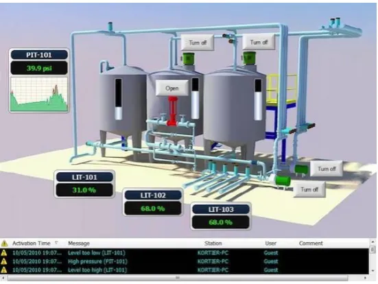
[image:30.595.160.436.204.411.2]HMI systems provide a visual representation of a control system, real time data acquisition and a user-friendly centralised control centre while allowing the user to build almost any application and maintain it easily through a variety of flexible software (Anaheim Automation 2016).
Figure 5: Example HMI screen of a plant process (Katzel 2012)
Figure 5 shows an image of an example HMI design for a plant process that allows the viewer to read continuous data (i.e. tank and pressure levels), discrete data (i.e. pump on/off status), and allows real world changes to be made to the plant (i.e. turning pumps on/off) (Rohee, Riera & Carré-Ménétrier 2007)
16
17
3.
Literature Review
This chapter explores existing literature in relation to nursing education frameworks, previous work in this project area, educational tool design techniques, and other existing remote access tools used for educational purposes.
3.1.
Current Framework of Nursing Education
As nursing becomes increasingly advanced, technologically and scientifically, expectations of graduate’s knowledge and skills are also increasing. Graduates are required to have the capability to make independent clinical decisions to ensure patient safety from the beginning of their career (Harwood 2011).
To ensure all graduates are clinically capable and meet the necessary professional requirements, the nursing’s educational framework revolves around the national standard of competency provided by the Nursing and Midwifery Board of Australia (NMBA). Registered nurses (RN) are required to meet these standards before joining the workforce and continue to adhere to throughout their careers (Mater Education 2016).
NMBA’s 2016 RN standards for practice consist of the following seven standards, a competent RN:
1. Thinks critically and analyses nursing practice. 2. Engages in therapeutic and professional relationships. 3. Maintains the capability for practice.
18 5. Develops a plan for nursing practice.
6. Provides safe, appropriate and responsive quality nursing practice. 7. Evaluates outcomes to inform nursing practice.
(Nursing and Midwifery Board of Australia 2016)
Figure 7: Registered Nurse Standards (Nursing and Midwifery Board of Australia 2016)
Standards 1 and 3 are most related to this research project due to its support for critical thinking, analysis of nursing practice and maintaining the capability for practice.
A basic framework tool is the Nursing Process which outlines five fundamental nursing steps: assessment, diagnosing, planning, implementing, and evaluating (Singh 2013).
3.1.1.
Pedagogical Aspects of Clinical Training
19
exposure to practical environments is necessary. Based on the standards above, an equal balance of both theoretical content and practical use of the content seems to be the preferred option.
Figure 8 illustrates a typical (modern) combination of higher-education pedagogical tools for nursing. Student learning occurs via traditional lectures and tutorials, problem based learning, clinical placements, ward simulations, and online learning. Bridging to the health care setting is mostly attributed to simulation and clinical practice.
Figure 8: Model of educational delivery and transition from learner to patient centred (Mater Education 2016)
20
Educators who preferred ‘meaningful’ methods attempted to make their content meaningful and more relevant through a variety of strategies, including clinical simulation, and by being clinically credible.
Educators who preferred ‘engaging’ methods attempted to make their content interesting to capture student’s attention via a variety of strategies, including the use of interactive games, engaging with students, as well as keeping a well-managed classroom environment.
A common and effective pedagogical approach for nurse education today is through simulated teaching and learning. Simulated in the sense of roleplay scenarios, not in an engineering sense (i.e. of an online or ‘virtual’ simulation). Undergraduate students often train in ‘mock’, simulated wards with manikin patients; however, the equipment (e.g. IV pumps) is all real. Effective simulations offer a method to integrate theoretical and practical learning without endangering real life patients. The large majority of research conducted on simulated clinical settings is extremely positive and overall state that these environments allow students to develop competence and confidence in a safe environment through meaningful and engaging scenarios (Berragan 2011) (Murray, Grant & Howarth 2008).
3.1.2.
Current IV Training Methods
21
3.2.
Medication Errors
Medication errors can have a serious negative impact, not only directly to the affected patient, but also indirectly to the professional reputation, personal wellbeing and integrity to the personnel at fault (Anderson & Townsend 2010).
The Oxford English Dictionary defines an error as something done incorrectly
through ignorance or carelessness; a mistake, for example in, calculation, judgement or action. Many other definitions exist, although, possibly a more relevant definition can be ‘a failure to complete a planned action as intended, or the use of an incorrect plan of action to achieve a given aim’ (Aronson 2009). More specifically, a medication error can be described as ‘a failure in the treatment process that leads to, or has the potential to lead to, harm to the patient’, where the treatment process refers to all medications (Aronson 2009).
The National Coordinating Council for Medication Error Reporting and Prevention (NCCMERP) organisation states a medical error is:
“Any preventable event that may cause or lead to inappropriate medication use or patient harm while the medication is in the control of the health care professional, patient, or consumer. Such events may be related to professional practice, health care products, procedures, and systems, including prescribing; order communication; product labelling, packing and nomenclature; compounding; dispensing; distribution; administration; education; monitoring; and use.” (NCCMERP 2016)
22
For a range of medical steps, possible errors can occur when:
deciding which medicine and dosage regimen to use
prescribing faults i.e. irrational, inappropriate and/or ineffective prescribing, under-prescribing, over-prescribing
writing the prescription
prescription errors: i.e. incorrect spelling, unintelligible handwriting
manufacturing the formulation
wrong strength, contaminants, wrong or misleading packaging
dispensing the formulation
wrong drug, wrong formulation, wrong label
administering or taking the medicine
wrong dose, wrong route, wrong frequency, wrong duration
monitoring therapy
failing to alter therapy when required, erroneous alteration (Aronson 2009)
Seen in Table 1, J.K Aronson (2009) also categorises medication errors into: Knowledge based, Rules based, Action based and Memory based errors.
Table 1: Error categories, adapted from J.K Aronson (2009)
Error Category Brief explanation
Knowledge Lack of knowledge e.g. unsure how to program IV pump correctly,
prescribing drug incorrectly
Rules Bad rule e.g. misapplying a good rule
Action Accident e.g. selecting wrong drug
Technical Writing illegibly, e.g. ‘Panadol’ is dispensed instead of ‘Pridadel’
Memory Lapses e.g. forgetting patient’s allergies, forgetting to set a
23
Other studies have categorised errors into procedural and clinical errors. Procedural errors where those similar to forgetting to check ID of patient, didn’t check drug packaging for expiry date, failed to record administration data afterwards. Clinical errors where those similar to administering an incorrect amount or rate of IV fluids, administering drug 1 hour or more on either side of the prescribed administration time.
Nichols, et al. (2008) conducted a qualitative study at a Fremantle teaching hospital, in 2005, to study the clinical contexts contributing to harmful medication errors finding approximately 57% of the observed staff members contributed to a significant medication error. The study also stated “most errors were due to slips in attention that occurred during routine prescribing, dispensing or drug administration”, these types of mistakes can be categorised as action based. Knowledge based errors were mostly caused by prescribers failing to acquire relevant information before prescribing unfamiliar drugs (Nichols et al. 2008).
International organisation, the Institute for Safe Medication Practices, has identified 10 key elements that can lead to medication errors:
patient information
drug information
adequate communication
drug packaging, labelling, and nomenclature
medication storage, stock, standardization, and distribution
drug device acquisition, use, and monitoring
environmental factors
staff education and competency
patient education
24
Overall, the literature points to the majority of errors occur due to lapses in focus, communication and memory; where these lapses were often caused by fatigue and stress. Nichols et al. (2008) supports this by stating “errors were more likely to occur during tasks being carried out after hours by busy, distracted staff, often in relation to unfamiliar patients”.
3.2.1.
General Medication Error Statistics
Anderson & Townsend (2010) point out that most errors in the administration phase are executed by nursing - since administration is usually performed by nurses. Administration errors account for 26% - 32% of total general medication errors.
“Overall, 80% of medicine administrations were associated with either a procedural or clinical error, with 74% of medicine administrations associated with a procedural error and 25% associated with a clinical error.” (Roughead, Semple & Rosenfeld 2013)
25
3.2.2.
IV Specific Medication Administration Error Statistics
IV fluid administration is a crucial component of clinical care. IV administration errors can be extremely detrimental to patients and thus can increase admission time and healthcare costs. Although IV administration errors are very serious, little is known about them. Most existing research and data was accumulated in the 1990’s or outside of Australia. Two stand-out studies have been performed in Australia since 2000, Han, Coombes & Green (2005) and Westbrook et al. (2011), both of which indicate moedrate to high IV administration error rates and have been used as references in numerous other sources, including the Australian Commission on Safety and Quality in Health Care review in 2013. Table 2 below displays error rates from a range of studies illustrating the erractic results even within Australia i.e. 11.5% to 69.7%.
Table 2: IV administration error rates from international literature. Origin of
Study
Percentage of administrations where at least one error occurred
Literature
Germany 53% (Taxis & Barber 2004)
UK 49% (Taxis & Barber 2004)
Brazil 81% (Hoefel et al. 2008)
Australia 11.5% (Breeding et al. 2013)
Australia 18% (Han, Coombes & Green 2005)
Australia 69.7% (Westbrook et al. 2011)
The last study in the above table, Westbrook et al. (2011), observed 568 IV administrations, 69.7% had at least one clinical error and 25.5% of these were serious. The wrong rate was the most frequent error type and accounted for approximately 94% of the serious errors.
26
In Table 3 above, the highlighted data from Roughead, Semple & Rosenfeld (2013) originated from an IV fluid administration study, Han, Coombes & Green (2005), conducted across three surgical wards in the one Australian training hospital. This study observed a total number of 687 opportunities for error, with 124 of those opportunitites resulting in an error - equating to 18% of IV fluid administrations having at least one error.
27
3.2.3.
Medication Administration Error Prevention
Across the board internationally there is a wide range of literature in relation to preventing general medication administration errors yet there is a limited number of sources addressing strategies for prevention of IV medication administration errors specifically. Most prevention strategy suggestions are aimed towards promoting safer practice amongst undergraduate nursing students whether in regards to general medication or IV treatment administration. A few sources suggest maintaining healthy work environments to minimise stress and fatigue levels in nurses; however, realistically, the nursing profession is very demanding mentally and physically - little can be done in this prevention area.
Suggested prevention strategies were predominantly focused on increasing practical training before placement, increasing knowledge of equipment use and calculating dosage rates, following checklists to minimise errors from carelessness and lapses in concentration - all aimed towards nurse training.
In regards to specifically IV administrations, Westbrook et al. (2011) saw a 10 - 18% decrease in error rates for each additional year of experience the administering nurse accumulated for the first 6 years of experience. Some sources discussed the use of ‘smart pump’ technology, which refers to the use of IV pump software that aids in error prevention by capturing the error before it reaches the patient (Nichols et al. 2008).
Many nursing education providers and studies suggest adhering to a procedural checklist for general medication administration, commonly referred to as the ‘6 Rights’.
‘6 Rights’
28 Anderson (2010) suggests the following extras:
Right reason for the drug? Right documentation? Right evaluation and monitoring?
The ‘6 Rights’ checklist helps to ensure the correct patient is being treated with the right drug, with the right amount through the right route and at the right time, followed by recording the administration in the medication records. The ‘right to refuse’ refers to the patient’s right to refuse medication and also the clinician’s right to withhold administration if they feel necessary to do so.
Overall, excluding the previous IVPE’s documentation, there is a distinct lack of literature addressing specific educational technology tools and resources designed to prevent IV medication and infusion errors occurring.
3.3.
Previous Work - Baxter IVPE
Firstly, the difference between simulation and emulation must first be defined before continuing with this section. Gaba (2001) defines a simulation as “a technique – not a technology – to replace or amplify real experiences with guided experiences that evoke or replicate substantial aspects of the real world in a fully interactive manner”. While Webster (2008) defines emulation as, for example, “having a computer act exactly like [a piece of equipment]”. Another way to describe the difference is that a simulator is an environment which models, but, an emulator is one that replicates the usage as on the original device or system.
29
refinement, implementation, and evaluation of an online intravenous pump emulator, including outcomes for clinical practice for nursing students, in 2015,
based on developing (with Osbourne and Bowtell) and evaluating the success of the Baxter IVPE. USQ’s Nursing and Midwifery staff continue to use this tool for training first year nursing students in the Semester 2’s practical sessions. Entry level students are the only level to be trained with the Baxter pump as it is a relatively simple pump although it is no longer commonly used in the Australian health workforce.
Osbourne (2012) trialled two emulation methods for the Baxter IVPE, the first method involved using appropriate IV pump hardware controlled by a PLC and HMI software on a dedicated PC. Whereas the second method involved no physical pump hardware, only PLC and HMI software on a dedicated PC. The second option proved most effective emulation method, as well as the easiest to implement and the most cost effective.
Figure 9: Existing System (Real IV Pump - Left, Emulated Pump - Right) (Osbourne 2012)
30
Desktop (SGD). RDP is a proprietary protocol developed by Microsoft, allows a user to connect to a computer running Windows from another computer running Windows that's connected to the same network or to the Internet (assuming all settings and permissions are correct). The Baxter IVPE included three main sections: resources, a learning mode and an assessment mode (see Figure 10, Figure 11 & Figure 12).
Baxter IVPE second method resources are as follows: PLC H/W: Siemens S71200 PLC
[image:45.595.210.386.374.520.2]PLC S/W: Siemens TIA Portal v10.5 HMI S/W: Siemens WinCC Flexible 2008 HMI H/W: PC accessed through RDP
Figure 10: Baxter IPVE Welcome Screen (Osbourne 2012)
[image:45.595.205.390.566.700.2]31
Figure 12: Screen capture of Baxter IVPE during Assessment Mode
After extensive testing, student assessment, surveys and trialling, it was found that face-to-face teaching with real pump was as effective as training with the IVPE on its own, however, results significantly improved when both methods of IV Pump training were used.
Testing of IVPE and USQ nursing students was conducted in three groups; one group of on-campus students with only real pump access, one group of external students with only IVPE access, and the last group was a combination of on campus and external students with access to both the IVPE and the real pump. The last group (Group 3) performed the best out of the 3, while Group 1 & 2 performed similarly.
Group 1: ONC – Real Pump ONLY Group 2: EXT – IVPE ONLY
Group 3: ONC & EXT – Real Pump & IVPE
32
Additional data from Terry (2015) showed students mostly felt accessing and booking the IVPE through RDP and the booking system was not ideal and discouraged extra voluntary use. The booking system also limited access to only one individual at a time.
The above results from Terry (2015) and Terry et al. (2016) are extremely important to this project as they highlight the need for a new IVPE (with a more effective remote access solution) to enhance learning capabilities.
3.4.
Learning with Information and Communications
Technologies
33
occur when meaningful and discovery learning are combined (upper right quadrant of Figure 13).
Figure 13: Learning activities categorised by two dimensions (Grabe & Grabe 2007)
Attempts to improve learning through ICT have been ongoing since its arrival, most have been influenced by several theories of learning, namely behavioural, cognitive and social learning theories (Barak 2006). Barak (2006) outlines four instructional principles for effective design and use of ICT supported learning: learning is contextual, learning is an active process, learning is a social process, and reflective practice plays a central role in learning.
3.4.1.
Designing ICT tools for educational purposes
34
1.5.2.
Remote Access Technologies in Education
Literature in relation to online learning/remote access learning/e-learning all agree that
online technologies allow for students to participate in learning activities when time permits and this freedom has greatly increased the opportunities for many students to participate
in formal programs (Oliver 2002).
Although online material can be considered ‘remote access’ outside of engineering and IT faculties, within them remote access is more technical; for example gaining access to a PC or camera feed in an engineering laboratory through the network or through the internet. University of Southern Queensland’s engineering faculty runs multiple remote access laboratories for research, experiments and teaching.
“Our Remote Access Laboratory (RAL) system provides students, communities and
industry with off-site access to practical and laboratory experiments - bridging the
gap between real-life and virtual learning spaces… RAL allows students, regardless
of location, to actively engage in contextual action-oriented learning and achieve
course objectives with less emphasis on attending on-campus training sessions.”
(University of Southern Queensland 2015)
35
4.
Task Analysis & Project Methodology
This chapter outlines the project methodology including: planning, design and test procedures, resources required, project completion timeline, ethical components, and risk management associated with development and completion of the IVPE.
4.1.
Project Planning
In the case of large projects, it is best to break down the requirements and goals of the whole project into manageable portions for effective productivity and transitional flow throughout the length of the project. Additionally, separating the project into tasks allows for easier goal and progress evaluation. Planning elements such as an ethics, risk and resources analysis are also necessary for a successful project.
4.2.
Task Plan & Analysis
The project objectives specified in Appendix A – Project Specification are useful for breaking down the project into main tasks.
Initial Investigation & Background Research
36 Design Planning & Development
Design planning and development does not involve software development, only the development of learning and assessment mode purposes, learning resources content, structure of modes and pages within IVPE.
Software & Communications Development
This phase implements the previous phase’s planned designs with hardware and software. Communications setup between PLC, HMI and PC is required before software development can be implemented. Within this phase a design and test procedure can be followed for specific, small software implementation tasks (see section 4.2.1). The remote access and webserver functions of the HMI panel with be investigated in this phase as well. (Chapter 6 IVPE Software Development will focus largely on this phase of the task plan).
Evaluation & Results
Results will be obtained through evaluating the level of completion attained by the final stages of the project, and the level to which the system meets design and project objectives. Additional evaluation will stem from my personal qualitative analysis of the system, peer and supervisor feedback, survey results obtained from IVPE, and responses to research questions.
4.2.1.
Design & Test Procedure
37 Define Task/Problem
Determining what the task is and what it should achieve, it could be a small a task as creating a push button to close a text box. Keep the task as simple as possible. Consider the users action and the emulator’s reaction.
Develop Idea
Consider ways to solve the problem/complete the task. Determine the best way to program/design the idea.
Create HMI
Create the task/graphic/button and its associated memory address and nickname (address and nickname together will be referred to as the ‘tag’ from here on). Check layering and visibility.
Import to PLC
HMI database of tags needs to be imported to PLC program before programming this task.
Write Logic
38 Download to PLC & Run
Once the coded sequence seems sufficient, save, compile and download to the PLC. Ensure the program on the PLC is up-to-date.
Test & Debug
Once the program is running, test to locate any bugs in the code. Make any necessary changes or improvements. If changes are made return to Download to PLC & Run phase.
Final Check
A final check must be done to ensure task has been completed sufficiently, flows into the existing logic and HMI, and if the task is a pump function - that it is an accurate emulation. If any of these are unsatisfactory return to Develop Idea phase.
4.3.
Resource Analysis
39
Table 4: Required Resources and Approximated Costs
4.3.1.
PLC Specifications & Resources
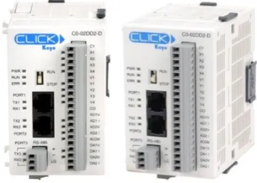
PLC resources include the PLC itself (see Figure 14) and the CLICK programming software (C0-PGMSW) that is available for free download. Other accessories to be used in conjunction with it are a 24V DC power supply, RS232 to USB programming cable, and a connection cable to HMI panel.
Figure 14: CLICK Koyo C0-02DD2-D PLC (Automation Direct 2016) Resource Quantity Cost ($AU) Cost (hrs) Comment CareFusion Alaris™ IV
Infusion Pump
1 - - Access available to
pump at USQ Koyo Click PLC
(C0-02DD2-D)
1 240 - Available from USQ
PLC 24V DC supply 1 50 - Available from USQ
PLC USB to RS232 programming cable
1 40 Available from USQ
PLC CLICK software (C0-PGMSW)
1 0 - Free download from
automation direct HMI C-more EA9-T6CL
Touch Screen
1 700 - Available from USQ
HMI C-more EA9-PGMSW program
1 180 - Licence for PC
available from USQ
Ethernet Cable 1 5 - Available from USQ
USQ Staff Support 1 - 21 Allocated staff time
per student
USQ Laboratory Access 1 - 120 Estimate
40
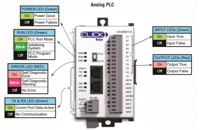
[image:55.595.129.468.346.567.2]The CLICK Koyo C0-02DD2-D PLC is an analog model. Further hardware specifications can be seen in Table 5, Figure 15 and Appendix C – PLC Specifications. Data types and memory can be also seen in Appendix C.
Table 5: Comparison of PLC types (Automation Direct 2016)
Figure 15: C0-02DD2-D/C0-02DD1-D I/O, ports and indicators (Automation Direct 2016)
41
4.3.2.
HMI Specifications & Resources
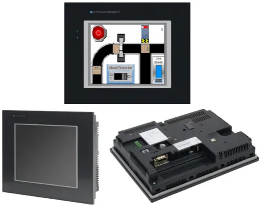
[image:56.595.163.434.324.536.2]HMI resources include the HMI panel itself (H/W) from the C-more EA9 touch screen interface panel series and the corresponding C-more HMI software. Other accessories to be used in conjunction with it is an Ethernet cable, and the possibility of a USB computer mouse and extra memory for data logging (i.e. USB or SD card). The EA9 series includes different sized screens with varying capabilities; however, for this project the EA9-T6CL 6 inch full feature model is used. The software C-more EA9-PGMSW is designed for all EA9 models. Figure 16 shows images of an EA9 panel.
Figure 16: HMI C-more Touch Panels (Automation Direct 2016)
42
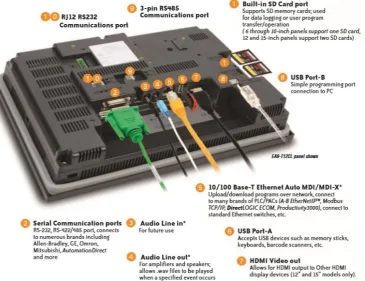
Figure 17: EA9-T6CL Features (Automation Direct 2016)
43
Figure 18: Example Picture of a HMI project being developed (Automation Direct 2016)
4.3.3.
Hardware & Communications Configuration Setup
Before design planning and software development phases can commence, initial set up of hardware and communication links between the PLC, HMI panel and PC need to be briefly addressed.
44
Table 6: PLC to PC connection ports, cables and protocols
PLC ↔ PC
Protocol Modbus RS232 ↔ USB
Connector
Type 6-pin phone cable RJ12 ↔ USB
Port Port 1 or 2 ↔ Any USB port
Table 7: PLC to HMI panel connection ports, cables and protocols
PLC ↔ Panel
Protocol Modbus RS485 ↔ Modbus RS485
Connector Type
Direct wiring between 3-wire removable terminal blocks ↔
Direct wiring between 3-wire removable terminal blocks
Port Port 3 ↔ Port 2 (#9 in Figure 17)
Table 8: Panel to PC connection ports, cables and protocols
Panel ↔ PC
Protocol Ethernet ↔ Ethernet
Connector
Type 8-pin Ethernet RJ45 ↔ USB
Port Ethernet Port (#5 in Figure 17) ↔ Ethernet Port
Figure 19: Programming Cable RS232/USB (Automation Direct 2016)
45
4.4.
Consequential Effects
Consequential Effects, Ethics, and Risk Analysis, Evaluation and Control have been relocated to Appendix E – Consequential Effects
4.5.
Project Timeline
46
5.
IVPE Initial Design Planning
This chapter briefly outlines visual and structural design planning stages, discusses design objectives, screen layout, navigation and purposes, and educational nursing information to include.
5.1.
Design Objectives
Design objectives were briefly touched on in the Introduction chapter. In order to achieve the same or higher learning levels than utilising an actual pump, design objectives for features and functions have been set out to produce the desired outcomes. Figure 20 outlines desired features, functions and outcomes of the IVPE.
Figure 20: IVPE Design Objectives adapted from (Terry 2015) and (Osbourne 2012)
5.2.
IVPE Page Structure & Navigation
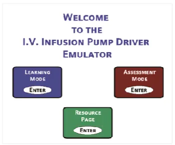
A basic structure diagram can be seen in Figure 21, beginning with a welcome page (similar to a ‘limitations of use’ page), then continuing on to the main ‘home’ display with options of continuing to Resources Page or Survey Page, or entering Learning Mode or Assessment Mode.
Features
• Engaging • Interactive • Meaningful
Functions
• Realistic and exactly emulates Alaris pump • User-friendly
(for non-techincal users)
Outcomes
• Student participation • Meets learning
objectives
47
Figure 21: IVPE Page Structure
Each block of Figure 21 will be discussed further in the following section.
5.3.
IVPE Mode Purposes & Content
Resource Page
48 Learning Mode
The learning mode walks the user through how to operate the pump with pop up hints at each step of the process that should automatically close if the step is completed or it is closed before completing the step. The level of guidance will be simple instructions such as ‘Press the […] button’, ‘Pump A’s alarm is on, check […]’.
Assessment Mode
Assessment mode has no guidance and the pump must be set up according to the requirements of different case studies. The user’s independent assessment attempts are assessed and results shown at the conclusion of assessment. Case studies to be included in the assessment mode have been reused from the Baxter IVPE as Dr Terry was satisfied with the activities to remain the same (see Appendix I – IVPE Assessment Case Studies).
49
Figure 22: Clinical Experiment Process Flowchart adapted from (Bowtell et al. 2012)
Survey
50
6.
IVPE Software Development
This chapter covers PLC/HMI software background followed by the software development in detailed phases. Not all PLC code with be shown throughout this chapter. Entire code listing can be seen in Appendix N – PLC Code Listing.
6.1.
Software Development Phases
Initial stages of development focuses on aesthetics of the IVPE; an effective emulator duplicates functions and visuals exactly (or as best as possible). Once the visual foundation is ready, pump functions and content development can begin. The remaining sections of this chapter will be structured as follows:
Software Background
HMI S/W design features (addressed in Chapter 4 - Section 4.3.2)
PLC S/W information
Data types & memory addressing
System data flow overview
Phase 1: HMI foundations & Pump Aesthetics
Document Alaris™ visuals
Develop foundation styles
Develop welcome pages and main menus
51
Phase 2: Develop Main Program & Resources Page
Develop structure and programming of resources page
Add content once programming is satisfactory
Phase 3: Foundation HMI/PLC development
Learning and assessment modes have the same base of HMI and programming
Simultaneous development of HMI/PLC as more pump functions/behaviours are added
This phase completed in segments i.e. do HMI of one pump function, then do PLC programming for that one function, then go back to HMI design for next function
Phase 4: Separate development of learning, assessment and survey modes
Foundation for learning and assessment modes are ready, break off into developing learning and assessment mode independently
Further learning mode development includes hints, guidance
Further assessment mode development includes assessment capabilities, PLC program tracking the user’s answers/operation of pump in comparison to the required steps for each case study
Phase 5: Final stages and remote access/webserver setup
Final stages of debugging and fixing
52
6.2.
Software Background
Before beginning HMI design and logic programming an understanding is required of what HMI features exist, PLC memory types and ranges are available, and lastly, what/how will the components communicate to each other. Cables, wiring and hardware configuration was discussed in Chapter 4 - Section 4.3.3; however, the ports in question must also be configured internally.
Data Types, Ranges & Memory Databases
The PLC protocol/driver (Automation Direct CLICK Serial) is specified to the HMI S/W when creating a new project, this way the program automatically acquires the PLC data types and ranges. Data types can be seen in Appendix C – PLC Specifications. The main data types and their possible memory address ranges:
Discrete Control Relay (BIT): C1 - C2000 Short Integer (INT): DS1 - DS4500 Double Integer (INT2): DD1 - DD1000
Control bits are utilised for on/off switching (set, toggle or momentary). Double integers will not be common; however they may be needed for large math operations. Apart from static shapes, text and bitmaps, objects in the HMI S/W will require a memory address with a ‘Tag Name’. The below Figure is a partial screen capture of HMI memory database - the PLC program also requires this data.
53
C-more and CLICK are from the same parent company which allows for memory database compatibility. The HMI database can be exported to a .csv file to be then imported into the PLC database; however minor formatting needs to occur first before importing to PLC.
HMI .csv Data Format:
ProtocolID, DeviceName, TagName, DataType, DataCount, Retentive, Address, ArrayStart, ArrayEnd
Figure 24: HMI tag database export file format
PLC .csv Data Format:
Address, DataType, Nickname, Initial Value, Retentive, Address Comment
Figure 25: PLC tag database export file format
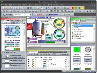
54 CLICK PLC Software
[image:69.595.102.496.271.541.2]The CLICK software control logic language used is called Ladder Logic which consists of placing contacts, outputs and functions on ‘rungs’ of a ladder. The software executes from left to right, top to bottom. A well-structured program maximises readability, efficiency and ease of fault-finding. A typical view of the PLC workspace can be seen in Figure 26.
Figure 26: A typical view of CLICK software
55 Data Flow
Lastly for software background, data flow and relationships between IVPE user, PLC and HMI is vital to the programming. PLC memory table is the database of tags, addresses and values. Figure 27 illustrates a rudimental data flow sequence that can be explained by: user does an action (i.e. clicks button), HMI reacts by setting necessary tags -> reaction seen by PLC -> PLC follows out actions for that change -> sends new data back to PLC. In the case of independent HMI actions, if an event triggers multiple actions where some are completed via PLC code and some are completed independently in the HMI software - there can be a short time delay between HMI code and HMI/PLC code.
`
Figure 27: Basic System Data Flow Diagram adapted from (Osbourne 2012)
6.3.
Phase 1: HMI Foundations & Aesthetics
56
A high quality photo of a PC with two pump modules was provided by the retailer website. The original photo was the most viable image but still required editing. Photoshop and Paint were used to trim, stretch and tilt the modules until they were more front-on angled with no side views. See Appendix J – HMI PC & Pump Graphics Development for comparison between original and edited, and see Figure 28 for final version.
Figure 28: IVPE Alaris Background Graphics (with tubing)
[image:71.595