1 INTRODUCTION
Dams and reservoirs provide significant benefits to the community, such as water supply, flood control and electricity generation. Unfortunately, they also represent one of the greatest potential risks to public safety, local and regional economies and the envi-ronment due to dam failures. During their long de-signed service life, unexpected changes in opera-tional conditions such as extreme floods, earthquakes and improper usage, incorporated with age-related deteriorations may cause damage to dam structures. If an initial damage in a dam is not de-tected, it can lead to increased damage and dam fail-ure. The needs to monitor dam structural perfor-mance and detect the onset of damage are thus evident. Structural Health Monitoring (SHM) has emerged as a feasible technique for this purpose by using on-structure, non-destructive sensing systems (Chan & Thambiratnam, 2011).
In order to have an effective SHM strategy, the structure needs to be monitored in the long-term and frequent or on an ideally continuous basis. In this regards, vibration-based structural health monitoring (VBSHM) offers one of the most reliable and cost-effective SHM approaches through the use of envi-ronmental and operational excitations (Nguyen,
2014). Along with the development of vibration monitoring systems, over the last three decades, a large amount of research on vibration-based damage detection (VBDD) has been conducted (Fan & Qiao, 2011). The fundamental idea of VBDD techniques is that when damage in a structure becomes reasonably significant, it can cause changes in its dynamic properties (mass, stiffness, and damping), and these in turn will cause detectable changes in the vibration characteristics (such as modal properties) (Doebling et al., 1998; Karbhari & Ansari, 2009; Sohn et al., 2004). Therefore, by assessing changes in modal pa-rameters (frequencies, mode shapes and modal damping), one can assess structural damage in terms of its presence, location and severity. Based on this basic idea, a variety of VBDD-based methods have been proposed. Among them, the techniques based on modal flexibility change (MFC) and changes in modal strain energy (MSE) were explored by a number of researchers for damage locating and esti-mating the severity of damage in beam-like and plate-like structures (Cornwell et al., 1999; Doebling & Farrar, 1996; Moradipour et al., 2015; Ni et al., 2008; Pandey & Biswas, 1994; Shi et al., 2000; Shih et al., 2009; Norris Stubbs, 1995; N Stubbs et al., 1992; Sung et al., 2014).
Damage assessment of concrete gravity dams using vibration
characteristics
N.T. Le
a,*, D.P. Thambiratnam
a, T.H.T Chan
a, A. Nguyen
a& B.K.T. Huynh
ba
School of Civil Engineering & Built Environment, Queensland University of Technology, Brisbane, Australia.
b National University of Civil Engineering, Hanoi, Vietnam.
* Email: [email protected]
ABSTRACT: Vibration-based Structural Health Monitoring (VBSHM) has emerged as a feasible technique in long-term monitoring, structural performance evaluation and damage assessment of civil structures. As an important aspect of the complete VBSHM system, over the last three decades, many vibration-based damage detection methods have been developed for buildings and bridges. However, the application of these tech-niques to concrete gravity (CG) dams has been limited. In the present study, damage indices based on changes in modal flexibility and modal strain energy are suitably enhanced to be applicable for plane-strain structures. They are then used to investigate the feasibility of detecting and locating damage in a finite element model of a CG dam without noise effects. Results show that the enhanced damage indices can be promising in locating damage in the upstream part of CG dams by using only the first lateral mode of vibration. In addition, it is necessary to monitor both horizontal and vertical mode shape components and use these for structural damage diagnoses in CG dams.
The merit of MFC-based damage detection (DD) methods lies on the fact that it combines mode shapes and natural frequencies, which makes it more sensitive to locating the damage compared to meth-ods based on the two separate modal parameters (Zhao & DeWolf, 1999). In addition, the method can eliminate the necessity of considering higher modes as the modal flexibility converges rapidly with in-creasing values of frequency. Therefore, the flexibil-ity matrix can be obtained by measuring only a few early modes of vibration. However, the drawback of this method is that it requires the identified mode shapes to be mass-normalized, which might cause significant difficulties in practice such as the need to have a correct and validated FE model or repeated testing involving mass changes (López Aenlle et al., 2005).
The MSE-based DD method, on the other hand, can avoid the requirement of mode-shape mass nor-malization which facilitates its application in real structures with modal properties obtained from am-bient vibration data (Cornwell et al., 1999). The method has been shown to be more sensitive to damage than other mode shape-based methods. However, it is more affected by noise and incom-plete measured data.
Though many VBDD-based methods have been proposed for other civil structures, their application to concrete gravity (CG) dams has been limited. One possible reason for this is that the development of current VBDD-based methods was started from simple structural elements, such as beams and plates, then suitably developed and applied to buildings and bridges. Therefore, the application of these methods to solid structures such as CG dams can have chal-lenges, especially when dealing with complicated in-teractions between dam and reservoir, as well as the foundation. In the present study, some existing MFC-based and MSE-based damage indices (DIs) are suitably modified and enhanced to be applicable for plane-strain structures. The feasibility of using the modified DIs for locating damage in a CG dam model is investigated. Various damage scenarios at the upstream face of the dam are introduced to ex-plore damage detection capability of the damage in-dices based on (i) relative change in modal flexibil-ity (∆F%, RFC) and (ii) modal strain energy (β*). The damage assessment, at this stage, is conducted without noise effects in modal parameters.
2 ENHANCEMENTS OF EXISTING MFC AND MSE-BASED DAMAGE INDICES FOR PLANE STRAIN STRUCTURES
2.1 Modal flexibility change damage indices
The modal flexibility matrix [F] can be approxi-mately obtained from low-order measured natural
frequencies and mass-normalized mode shapes as follows (Ni et al., 2008; Pandey & Biswas, 1994):
[𝐹𝐹]𝑁𝑁×𝑁𝑁≈[Φ]𝑁𝑁×𝑚𝑚[Ω]𝑚𝑚−1×𝑚𝑚[Φ]𝑚𝑚𝑇𝑇×𝑁𝑁
=� 1
𝜔𝜔𝑖𝑖2φ𝑖𝑖φ𝑖𝑖𝑇𝑇 𝑚𝑚
𝑖𝑖=1
(1)
where Φ=[φ1, φ2,…, φm] is the mode shape matrix; φi is the ith mode shape vector; Ω=diag(𝜔𝜔𝑖𝑖2) is the diag-onal matrix containing the eigen-frequencies; m is the number of measured modes; and N is the number of measured degree of freedoms (DOFs).
For beam-like and plate-like structures, N is the number of transverse DOFs and can be simply equated to n, where n is the number of measurement points. However, for vertically asymmetrical plane-strain structures such as CG dams, each mode shape vector comprises 2n mode shape components (MSC) representing the horizontal and vertical translational DOFs at each point. Therefore, N should be equal to
2n, and the dimensions of flexibility matrix are
2n×2n rather than n×n as can be frequently seen in beam-like or plate-like structures. This requires suit-able modifications when adopting the current MFC-based DIs to concrete gravity dams.
Damage in a structure alters its vibration charac-teristics and increases the flexibility. In the present article, the resulting relative flexibility change ma-trix between the healthy and the damaged states is adopted for damage location identification of CG dams:
[∆]2𝑛𝑛×2𝑛𝑛 =�𝛿𝛿𝑗𝑗𝑗𝑗�2𝑛𝑛×2𝑛𝑛=��𝐹𝐹𝑗𝑗𝑗𝑗 ℎ− 𝐹𝐹
𝑗𝑗𝑗𝑗𝑑𝑑�
𝐹𝐹𝑗𝑗𝑗𝑗ℎ � 2𝑛𝑛×2𝑛𝑛
(2)
where δjk is the relative flexibility change at the kth DOF causes by changes in flexibility at the jth DOF,
h and d denote the healthy and damaged states, re-spectively. Based on [∆], different DIs can be ex-tracted using either the maximum approach (Pandey & Biswas, 1994) and the diagonal approach (Doebling & Farrar, 1996; Ni et al., 2008). With re-gard to the first approach, for each measurement lo-cation k (k=1,𝑛𝑛), let ∆F%(H+V)k be the maximum value of the two corresponding continuous columns of [∆], i.e.,
∆𝐹𝐹%(𝐻𝐻+𝑉𝑉)𝑗𝑗 =𝑚𝑚𝑚𝑚𝑚𝑚 (
𝑗𝑗=1,2𝑛𝑛𝛿𝛿𝑗𝑗(2𝑗𝑗−1),𝛿𝛿𝑗𝑗(2𝑗𝑗)) (3)
where “H+V” denotes the use of both horizontal and vertical MSC. Regarding the second approach, let RFC(H+V)k be the greater value among the two corresponding diagonal elements, i.e.,
The DIs in Eq. (3) and (4) demonstrate changes of flexibility for each measurement locations. There-fore peaks should theoretically appear in the corre-sponding plot curves.
2.2 Modal strain energy-based damage index
The damage detection method based on changes in modal strain energy was first proposed for beam-like structure (N Stubbs et al., 1992). It was then devel-oped for plate-like structure (Cornwell et al., 1999). In the present work, the method will be expanded to plane-strain structures to be applicable for CG dams.
For a plane-strain problem, the strain energy of a section in XZ plane can be given by:
𝑈𝑈=12�(𝜎𝜎𝑥𝑥𝜀𝜀𝑥𝑥+𝜎𝜎𝑧𝑧𝜀𝜀𝑧𝑧+𝜏𝜏𝑥𝑥𝑧𝑧𝛾𝛾𝑥𝑥𝑧𝑧)𝑑𝑑𝑚𝑚𝑑𝑑𝑑𝑑 𝐴𝐴
(5)
From stress-strain and strain-displacement relation-ships, the strain energy associated with one particu-lar mode shape ith can be derived from eEq. (5) as follows:
𝑈𝑈𝑖𝑖 =𝐷𝐷2� ��𝜕𝜕𝑢𝑢𝜕𝜕𝑚𝑚 �𝑖𝑖 2
+�𝜕𝜕𝑤𝑤𝜕𝜕𝑑𝑑 �𝑖𝑖 2+ 2ν∗𝜕𝜕𝑢𝑢𝑖𝑖
𝜕𝜕𝑚𝑚 𝜕𝜕𝑤𝑤𝑖𝑖
𝜕𝜕𝑑𝑑
𝐴𝐴
+1−ν∗
2 � 𝜕𝜕𝑢𝑢𝑖𝑖 𝜕𝜕𝑑𝑑 + 𝜕𝜕𝑤𝑤𝑖𝑖 𝜕𝜕𝑚𝑚 � 2 � 𝑑𝑑𝑚𝑚𝑑𝑑𝑑𝑑 (6)
where D=E*/(1-ν*2) represents for the stiffness of the structure, E*=E/(1-ν2) and ν*=ν/(1-ν) = modi-fied (or effective) Young’s modulus and Poison’s ra-tio respectively, ui(x,z) and wi(x,z) = the ith horizontal and vertical MSC respectively, A = the area of the plane section. If A is divided into N sub-regions then the associated sub-region energy for the mode ith is given by:
𝑈𝑈𝑖𝑖𝑗𝑗=𝐷𝐷2𝑗𝑗� ��𝜕𝜕𝑢𝑢𝜕𝜕𝑚𝑚 �𝑖𝑖 2
+�𝜕𝜕𝑤𝑤𝑖𝑖 𝜕𝜕𝑑𝑑 �
2
+ 2ν∗𝜕𝜕𝑢𝑢𝑖𝑖
𝜕𝜕𝑚𝑚 𝜕𝜕𝑤𝑤𝑖𝑖
𝜕𝜕𝑑𝑑
𝐴𝐴𝑗𝑗
+1−2ν∗�𝜕𝜕𝑢𝑢𝜕𝜕𝑑𝑑𝑖𝑖+𝜕𝜕𝑤𝑤𝜕𝜕𝑚𝑚 �𝑖𝑖 2
� 𝑑𝑑𝑚𝑚𝑑𝑑𝑑𝑑
(7)
The corresponding damage index account for m
measured modes can be defined using the same con-cept with that of beam-like and plate-like structures (Cornwell et al., 1999) and is given by:
𝛽𝛽𝑗𝑗 =� 𝑓𝑓𝑖𝑖𝑗𝑗∗ 𝑚𝑚
𝑖𝑖=1
� 𝑓𝑓𝑖𝑖𝑗𝑗
𝑚𝑚
𝑖𝑖=1
� (8)
where
𝑓𝑓𝑖𝑖𝑗𝑗 =
∬ ��𝜕𝜕𝜕𝜕𝜕𝜕𝜕𝜕�2+�𝜕𝜕𝜕𝜕𝜕𝜕𝜕𝜕�2+2ν∗𝜕𝜕𝜕𝜕 𝜕𝜕𝜕𝜕𝜕𝜕𝜕𝜕𝜕𝜕𝜕𝜕+1−
ν∗
2 �𝜕𝜕𝜕𝜕𝜕𝜕𝜕𝜕+𝜕𝜕𝜕𝜕𝜕𝜕𝜕𝜕� 2
� 𝑑𝑑𝑥𝑥 𝑑𝑑𝑧𝑧
𝐴𝐴𝑗𝑗
∬ ��𝜕𝜕𝜕𝜕𝜕𝜕𝜕𝜕�2+�𝜕𝜕𝜕𝜕𝜕𝜕𝜕𝜕�2+2ν∗𝜕𝜕𝜕𝜕 𝜕𝜕𝜕𝜕𝜕𝜕𝜕𝜕𝜕𝜕𝜕𝜕+1−
ν∗
2 �𝜕𝜕𝜕𝜕𝜕𝜕𝜕𝜕+𝜕𝜕𝜕𝜕𝜕𝜕𝜕𝜕� 2
� 𝑑𝑑𝑥𝑥 𝑑𝑑𝑧𝑧
𝐴𝐴
(9)
The same relative change algorithm (used in the above modified MFC DIs) is reused to formulate the damage index:
𝛽𝛽𝑗𝑗∗= ABS�� 𝑓𝑓𝑖𝑖𝑗𝑗∗ 𝑚𝑚
𝑖𝑖=1
� 𝑓𝑓𝑖𝑖𝑗𝑗 𝑚𝑚
𝑖𝑖=1
� −1� (10)
It should be noted that the above formulated DI β* is based on mode shape slopes instead of mode shape curvatures as can be seen in the original DIs devel-oped for beam-like and plate-like structures.
3 APPLICATION TO CG DAM 3.1 Finite element model
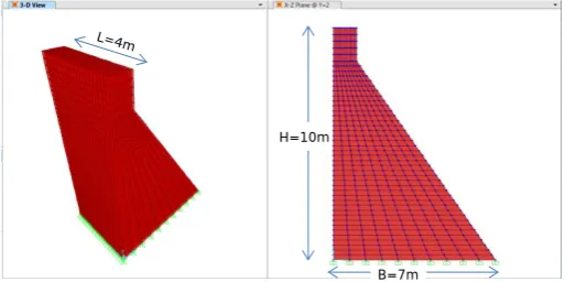
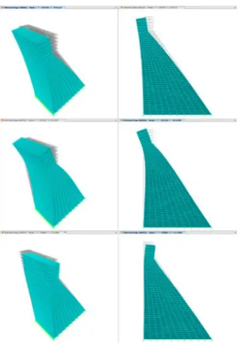
A CG dam block with fixed foundation and empty reservoir is developed as a Finite Element (FE) model (Figure 1). The dam is treated as a plane-strain structure and its modal frequencies (Table 1) and mode shapes (Figure 2) are obtained using the FE software package SAP2000. These vibration characteristics will represent the undamaged state of the structure. The FE model will then be analyzed with different damage scenarios in order to deter-mine the modal parameters in the damaged states.
[image:3.595.307.564.535.663.2]The dam is of concrete with a height of 10m, a base width of 7m and a (longitudinal) length of 4m. The Young’s Modulus, Poisson’s ratio and mass density for the dam structure are 25GPa, 0.2 and 2400kg/m3 respectively.
[image:3.595.319.534.705.761.2]Figure 1. The FE model of the concrete dam block structure
Table 1. Modal frequencies (undamaged state) Mode
number Frequency (Hz)
Dominant vibra-tion direcvibra-tion 1 37.01 Lateral 2 83.10 Lateral 3 112.25 Vertical
H=10m
Figure 2. Three first mode shapes in the undamaged state
3.2 Damage scenarios
Upstream face and lower part of the dam are the most vulnerable parts of concrete gravity dams un-der operational conditions. Damage scenarios are then introduced on elements in the corresponding parts of the FE model. Damage is simulated by re-ducing the material Young’s modulus by 20%. Di-mensions of the damaged elements are approximate 2% of the dam height, 5% of the dam length, and 10% of the dam width.
It is very difficult to monitor all sections of the dam, especially in the most vulnerable parts. One possible solution is to assess changes in vibration characteristics at some sections in order to predict the relative damage areas. The present study will ex-amine upstream joints in three sections S1, S2 and S3 (Figure 3). Three damage cases were created in the model including single and multiple damaged positions. The damage is in section S2 in damage cases 1 and 3, while in the damage case 2 it lies far away from the three measurement sections.
(a) (b) (c) (d) Figure 3. Damage scenarios viewed from upstream face (a, b, c) and in cross section (d)
4 DAMAGE DIANOSIS BY THE ENHANCED DAMAGE INDICES USING THE FIRST LATERAL MODE
In all damage diagnosis cases below, only the first lateral mode is used.
4.1 Damage case 1: single damage at 1m above the dam’s base, lying on section S2
Figure 4 shows the plots of ∆F%(H+V) and
RFC(H+V) that account for both horizontal and ver-tical MSC, and of ∆F%(H) which accounts for just the horizontal MSC. Similarly, Figure 5 illustrates the β*(H+V) and β*(H) values for the first damage scenario. It can be seen that all DIs using both MSC components accurately predict the damage location, while those using only the horizontal MSC give rela-tively less definite results.
[image:4.595.76.247.30.274.2]
Figure 4. Flexibility damage indices – Damage case 1
Figure 5. Modal strain energy damage indices – Damage case 1
4.2 Damage case 2: single damage at 0.1m above the dam’s bottom, lying far away from the measurement sections.
[image:4.595.307.541.282.578.2] [image:4.595.36.287.605.739.2]CG dams when the higher mode shapes at upstream-face elements are difficult to measure.
Figure 6. Flexibility damage indices – Damage case 2
Figure 7. Modal strain energy damage indices – Damage case 2
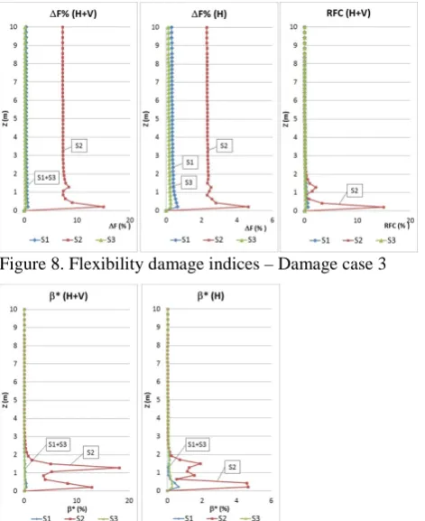
4.3 Damage case 3: multiple damage positions lying on section S2 (one at the dam bottom, the other at 1m above)
In this damage scenario, the flexibility DIs just can provide dominant peaks at the lower damage loca-tion and less prominent peaks at the upper damage location as seen in Figure 8.
Figure 8. Flexibility damage indices – Damage case 3
Figure 9. Modal strain energy damage indices – Damage case 3
On the other hand, the modal strain energy (MSE) DIs can provide clear peaks at both damage posi-tions (Figure 9). In addition, it can be seen that the use of both horizontal and vertical MSCs provide better damage indicators.
5 CONCLUSION
This paper treats the damage assessment in a con-crete gravity dam using vibration characteristics. Suitable modifications and enhancements have been made to the existing MFC and MSE-based DIs to be applicable for plane-strain structures such as con-crete gravity dams. The effectiveness of these DIs in identifying the damage location was investigated in a theoretical FE model for single and multiple dam-age scenarios. The following conclusions are drawn from this study: (1) All the enhanced DIs based on changes in modal flexibility [∆F%(H+V) and
RFC(H+V)] and strain energy [β*(H+V)] can accu-rately locate single and multiple damage that lie on one of the measurement sections; (2) In the case when damage does not lie on the measured sections, the enhanced DIs are still able to provide infor-mation for identifying the damaged section and the damage location; (3) Only the first lateral mode is required in all damage scenarios; (4) In most of the damage cases, DIs using both horizontal and vertical MSC accurately predict the damage location, while those using only the horizontal MSC give relatively less definite results
6 ACKNOWLEDGEMENTS
The present work forms a part of a study on struc-tural health monitoring of civil structures at Queens-land University of Technology (QUT), Australia. N.T. Le is a QUT PhD student supported by an Aus-tralia Awards Scholarship. This support is kindly acknowledged. The guidance provided by the super-visors is also greatly appreciated.
REFERENCES
Stubbs, N., Kim, J., & Topole, K. (1992). An efficient and robust algorithm for damage localization in offshore platforms. Paper presented at the Proceedings of the ASCE Tenth Structures Congress.
Pandey, A. K., & Biswas, M. (1994). Damage detection in structures using changes in flexibility. Journal of Sound and Vibration, 169(1), 3-17.
[image:5.595.33.269.491.780.2]Doebling, S. W., & Farrar, C. R. (1996).
Computation of structural flexibility for bridge health monitoring using ambient modal data. Paper presented at the Proceedings of the 11th ASCE Engineering Mechanics Conference.
Doebling, S. W., Farrar, C. R., & Prime, M. B. (1998). A summary review of vibration-based damage identification methods. Shock and vibration digest, 30(2), 91-105.
Cornwell, P., Doebling, S. W., & Farrar, C. R. (1999). Application of the strain energy damage detection method to plate-like structures. Journal of Sound and Vibration, 224(2), 359-374.
Zhao, J., & DeWolf, J. T. (1999). Sensitivity Study for Vibrational Parameters Used in Damage Detection. Journal of Structural Engineering, 125(4), 410-416.
Shi, Z., Law, S., & Zhang, L. M. (2000). Structural damage detection from modal strain energy change. Journal of engineering mechanics, 126(12), 1216-1223.
Sohn, H., Farrar, C. R., Hemez, F. M., Shunk, D. D., Stinemates, D. W., Nadler, B. R., & Czarnecki, J. J. (2004). A review of structural health monitoring literature: 1996-2001: Los Alamos National Laboratory Los Alamos, NM.
López Aenlle, M., Brincker, R., & Fernández Canteli, A. C. (2005). Some methods to determine scaled mode shapes in natural input modal analysis.
Ni, Y., Zhou, H., Chan, K., & Ko, J. (2008). Modal Flexibility Analysis of Cable‐Stayed Ting Kau Bridge for Damage Identification.
Computer‐Aided Civil and Infrastructure Engineering, 23(3), 223-236.
Karbhari, V. M., & Ansari, F. (2009). Structural health monitoring of civil infrastructure systems: Elsevier.
Shih, H. W., Thambiratnam, D. P., & Chan, T. H. T. (2009). Vibration based structural damage detection in flexural members using multi-criteria approach. Journal of Sound and Vibration, 323(3), 645-661.
Fan, W., & Qiao, P. (2011). Vibration-based damage identification methods: a review and comparative study. Structural Health Monitoring, 10(1), 83-111.
Nguyen, T. (2014). SHM through flexible vibration sensing technologies and robust safety evaluation paradigm. (Dissertation/Thesis), Queensland University of Technology. Sung, S., Koo, K., & Jung, H. (2014). Modal
flexibility-based damage detection of cantilever beam-type structures using baseline modification. Journal of Sound and Vibration, 333(18), 4123-4138.
Moradipour, P., Chan, T. H., & Gallage, C. (2015). An improved modal strain energy method for structural damage detection, 2D simulation.