i
MANUFACTURING DATA MANAGEMENT SYSTEM (MDaS)
WONG KOK HONG
This report is submitted in partial fulfilment of the requirements for the award of Bachelor of Electronic Engineering (Computer Engineering) With Honours
Faculty of Electronic and Computer Engineering Universiti Teknikal Malaysia Melaka
ii
UNIVERSTI TEKNIKAL MALAYSIA MELAKA
FAKULTI KEJURUTERAAN ELEKTRONIK DAN KEJURUTERAAN KOMPUTER
BORANG PENGESAHAN STATUS LAPORAN
PROJEK SARJANA MUDA II
Tajuk Projek : MANUFACTURING DATA MANAGEMENT SYSTEM
(MDaS)
Sesi Pengajian : 2010/2011
Saya WONG KOK HONG
mengaku membenarkan Laporan Projek Sarjana Muda ini disimpan di Perpustakaan dengan syarat-syarat kegunaan seperti berikut:
1. Laporan adalah hakmilik Universiti Teknikal Malaysia Melaka.
2. Perpustakaan dibenarkan membuat salinan untuk tujuan pengajian sahaja.
3. Perpustakaan dibenarkan membuat salinan laporan ini sebagai bahan pertukaran antara institusi
pengajian tinggi.
4. Sila tandakan ( √ ) :
SULIT*
(Mengandungi maklumat yang berdarjah keselamatan atau kepentingan Malaysia seperti yang termaktub di dalam AKTA RAHSIA RASMI 1972)
TERHAD* (Mengandungi maklumat terhad yang telah ditentukan oleh organisasi/badan di mana penyelidikan dijalankan)
TIDAK TERHAD
Disahkan oleh:
__________________________ ___________________________________
(TANDATANGAN PENULIS) (COP DAN TANDATANGAN PENYELIA)
Alamat Tetap: 12, Tingkat Pasir Putih, 1, Taman Yik Sang, 31650 Ipoh,Perak,
iii
“I hereby declare that this report is the result of my own work except for quotes as cited in the references.”
Signature :
iv
“I hereby declare that I have read this project report and in my opinion this project report is sufficient in terms of the scope and quality for the award of Bachelor of
Electronic Engineering (Computer Engineering) With Honours.”
Signature : ……….
Name of Supervisor : Eng. Siva Kumar S/O Subramaniam
v
Specially..
To my beloved parents
To my kind brothers and sisters
And not forgetting to all friends
For their
vi
ACKNOWLEDGEMENTS
First at all, I would like to express my thankfulness to our God because I manage to finish my final year project for the degree within two semesters as long period final year project at Universiti Tecknikal Malaysia Malaka (UTeM) and the report is submitted exact on time. Base on that, I already fulfill the requirement of the BENU 4972 and BENU 4984.
Second, I would like to show my gratitude for those who have assisted and guided me during the development and research of this Final Year Project (FYP). FYP supervisor, Mr Siva Kumar S/O Subramaniam does give lots of advice and assists during the development process of the project, besides he also guide and lead my project to the correct path for development. He also helps me for the project scheduling and set mile stone in order to increase my passion and ensure the project is delivering on time. He is great when he directly give help whenever is needed even he is needed to assist a lot of projects at the same time and all projects are working well with his helps.
vii
ABSTRACT
viii
ABSTRAK
ix
TABLE OF CONTENTS
CHAPTER TITLE PAGE
PROJECT TITLE i
CONFIRMATION REPORT STATUS ii
DECLARATION iii
SUPERVISOR CONFIRMATION iv
DEDICATION v
ACKNOWLEDGEMENT vi
ABSTRACT vii
ABSTRAK viii
TABLE OF CONTENT ix
LIST OF TABLE xii
LIST OF FIGURE xiii
LIST OF ABBREVIATION xvi
I INTRODUCTION 1
1.1 Introduction 1
1.2 Objectives 3
1.3 Problem Statement 4
1.4 Scope of Work 4
1.5 Methodology 6
1.6 Existing Production Monitoring System 7
1.6.1 White Board 7
1.6.2 Machine Controllers and Programmable Logic Controller (PLC)
x
CHAPTER TITLE PAGE
1.7 Introduction to Manufacturing Data Management System (MDaS)
8
II LITERATURE REVIEW 10
2.1. Microsoft Visual Studio .Net 2005 10
2.2 Microsoft Access 2007 11
2.3 Programmable Logic Controller 12
2.3.1 Conventional Controller 14 2.3.2 Programmable Logic Controller 15 2.3.2.1 Central Processing Unit 15
2.3.2.2 Input 16
2.3.2.3 Output 17
2.3.3 Programmable Logic Controller (Software)
17
2.4 Overall Equipment Effectiveness (OEE) 18
2.4.1 OEE Factor 19
2.4.1.1 Availability 20
2.4.1.2 Performance 21
2.4.1.3 Quality 21
2.4.2 Six Big Losses 22
2.5 Microcontroller (Microchip PIC 16F877A) 24
III PROJECT METHODOLOGY 31
3.1 Introduction 31
xi
CHAPTER TITLE PAGE
IV RESULT AND DISCUSSION 38
4.1 Casting and the Configuration of Switches 39 4.2 Overall Equipment Effectiveness Software 41
4.2.1 Login Form 42
4.2.2 User Menu Form 44
4.2.3 Data Base Viewing Form 45 4.2.4 Data Collection Form 46
4.2.5 Analysis Form 47
4.3 Programmable Logic Controller 52
4.4 Peripheral Interface Controller 54
4.5 Count Up Circuit 57
V CONCLUSION AND FUTUTE WORKS 60
5.1 Conclusion 60
5.2 Future Works 61
5.2.1 Integrate Notification Unit Short Messaging System
61
REFERENCES 63
Appendix A PROGRAM OF THE CONTROL UNIT 66
A.1 Design of the PIC Program 66
A.2 Design of the PLC Program 68
xii
LIST OF TABLES
NO TITLE PAGE
2.1 Six big losses 22
2.2 Key features of Microchip PIC 16F877A 27
2.3 Baud Rate of asynchronous mode compare with error rate
30
4.1 Explanation of Figure 4.1 39
4.2 Input ports of the PLC 52
4.3 Output ports of the PLC 52
4.4 Connection between PLC and PIC 55
4.5 Changes to the OEE software 55
4.6 Input and output port of the relay card to the count up circuit
xiii
LIST OF FIGURES
NO TITLE PAGE
1.1 Semi automated production line 2
1.2 Automated production line 2
1.3 Manual production line 3
1.4 General methodology of the project 6
1.5 Production status indicator board 7
1.6 Tracking software 8
2.1 Process control system 13
2.2 Elements in PLC 14
2.3 Conventional control system 15
2.4 Input connection to PLC 16
2.5 Ladder diagram 17
2.6 Connection hardware to PLC 18
2.7 Plant operating time 19
2.8 Planned production time 20
2.9 Availability 20
2.10 Performance 21
2.11 Quality 21
2.12 Pin configuration for PIC 16F877A 26
2.13 Bit configuration for transmit status and control register for Microchip PIC16F877A.
28
2.14 Bit configuration for receive status and control register for Microchip PIC 16F877A.
28
xiv
NO TITLE PAGE
3.2 Methodology for software development 34
3.3 Methodology for development serial communication devices
35
3.4 Methodology for hardware display and the prototype 36 4.1 Manufacturing Data Management System hardware
casting
39
4.2 Dimension of the casting 41
4.3 Features provided by MDaS’s OEE software 42
4.4 Login form 42
4.5 Add new user form 43
4.6 User menu form 44
4.7 Database viewing form 45
4.8 Data collection form 46
4.9 Data Analysis Form 47
4.10 Man Power Performance Report 48
4.11 Performance of department 49
4.12 Overall Equipment Effectiveness report 50
4.13 Production performance analysis report 51
4.14 Omron CQM1H-CPU42 52
4.15 Flow of the signals in MDaS 55
4.16 PIC 16F877A 55
4.17 USB to UART converter 55
4.18 Region changes with respond to the receive signals 57
4.19 Display board 58
4.20 Signal flow from push button to display board 58
A.2.1 Ladder Diagram 68
A.3.1 Schematic of 3 segment dispaly 70
A.3.2 Printed circuit board layout of 3 segment display 71
A.3.3 Schematic of 4 segment dispaly 71
A.3.4 Printed circuit board layout of 4 segment display 72
A.3.5 Schematic of relay card 72
xv
NO TITLE PAGE
A.3.7 Schematic of PIC circuit 73
xvi
LIST OF ABBREVIATION
MDaS - Manufacturing Data Management System PLC - Programmable Logic Controller
OEE - Overall Effectiveness Equipment IDE - Integrated Development Environment GUI - Graphical User Interface
OOP - Object-Oriented Programming
VB - Visual Basic
ADO - ActiveX Data Object COM - Component Object Model
SQL - Structured Query Language CPU - central processing unit
PIC - Programmable Interface Controller RISC - Reduced Instruction Set Computer
ADC - Analog-to-Digital-Convertor
MSSP - Master Synchronous Serial Peripheral
UART - Universal Synchronous Asynchronous Receiver Transmitter
A/D - Analog-to-Digital D/A - Digital-to-Analog
1
CHAPTER I
INTRODUCTION
This system is about designing a data collection system which can systematically collect data from a work cell in production line. The data will then be used for analysis purpose. Background of this system will be explained in later part of this report.
1.1 Introduction
Production information is very important for the management to analyze the actual or real time status of the work cells in production line. This ensures all the resources of the industry are fully utilized. The most practice conventional way in data collecting is manual data collection system. This type of data collection is quite popular in current industries due to the lack of investment, accuracy of system etc. However, there are a lot of problems are induced when using this manual data collection system. When this valuable data is collected manually, the probability of data collection inaccuracy is high because the system is interference by human. Human made error easily occur.
2
control issue and maintenance issue. These production data will be further analyzed to generate report regarding man power performance, respective department performance, production performance, and overall equipment effectiveness (OEE). These all report will be used to analyze man power performance, machine performance and overall production performance.
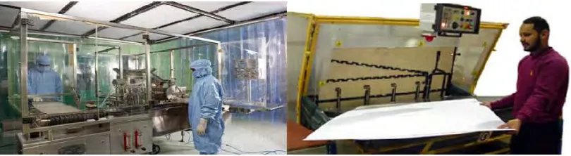
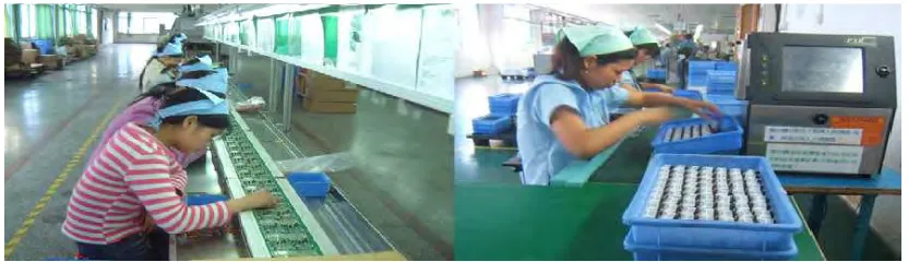
[image:18.595.114.529.298.421.2]Typically a production system in industries can be classified into three types, which are manual, semi automated machines and fully automated machines in nature. Manufacturing Data Management System (MDaS) can be integrated in any type of these production cells.
Figure 1.1: Automated production line
Production process using automated machineries as shown in Figure 1.1 is a process with high proportion of machinery in relation to workers. This type of process is suitable to serve large, relatively homogeneous populations consumers whose demand long production run and high quality output [1].
[image:18.595.115.520.613.724.2]3
[image:19.595.113.529.152.272.2]Semi automated production line as shown in Figure 1.2 consist of human and machineries working together to accomplish certain task. This type of production can only produce medium scale production output [1].
Figure 1.3: Manual production line
Manual production line is shown in Figure 1.3. Most of the work stations have their craftsman in the workbench. This type of process required skillful workers to follow procedures in producing parts. Such production lines practice for low production output [1].
1.2 Objectives
The main target of the project is focusing on designing a system which can automatically collects production data in order to improve the conventional data collection method. The objectives of the project are listed as below:
i. To design and develop an automatic data collection system.
ii. To have a systematic data collection system for each work cell in manufacturing company.
4
1.3 Problem Statement
The current collection method used in industry is not managed to provide accurate data to the management. As a solution to overcome this problem, the whole data collection system has to be automated without human intervened.
The percentage data error of manual data collection method is high due to human intervened. For example, the operator may misread an instrument or make a mistake in a calculation when they are collecting the production information. Other than that, random error also contributes a lot for the error in manual data collection. An example of random error could be when the operator making timings with a stopwatch. Sometimes operator may stop the watch too soon and sometimes too late. These two errors may cause the valuable production data inaccurate and eventually, the management makes the decision using fault data because of the deviation of the data.
Manufacturing Data Management System (MDaS) will overcome these problems since the system collect data automatically without human intervened and interference all times. MDaS is built with custom made software which is able to analyzed collected data accurately.
1.4 Scope of Work
This system will show the current status of the work cell. It consists of a hardware display and software. Sensors will be integrated to the machine which will be link to programmable logic controller (PLC). All the signals received by programmable logic controller will be sent to the customized software. MDaS shows all the collected information on the display board as well as software.
5
(OEE) and find out the weaknesses of current production cell.
6
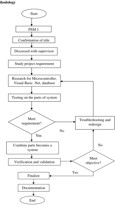
[image:22.595.167.534.71.739.2]1.5 Methodology
Figure 1.4: General methodology of the project Combine parts becomes a
system Yes Yes No Troubleshooting and redesign Yes No Start FYP 1
Confirmation of title
Discussed with supervisor
Study project requirement
Research for Microcontroller, Visual Basic .Net, database
Testing on the parts of system
Meet requirement? Finalize Documentation End Troubleshooting and redesign
Combine parts becomes a system
Verification and validation
Meet objective? Start
PSM 1
Confirmation of title
Discussed with supervisor
Study project requirement
Research for Microcontroller, Visual Basic .Net, database
Testing on the parts of system
7
1.6 Existing Production Monitoring System
Monitoring system is a necessary tool to the industry. It is being used to improve the industries daily production output and monitor the production outcome.
The following are the existing methods used in industries to provide information on the status of each work station, machineries or production line.
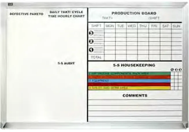
[image:23.595.156.483.298.526.2]1.6.1 White Board
Figure 1.5: Production status indicator board
8
[image:24.595.178.462.114.353.2]1.6.2 Machine Controllers and Programmable Logic Controller (PLC)
Figure 1.6: Tracking software
For automated machineries, they often have a real time tracking system as shown in Figure 1.6. This tracking software is customized made for each machine. This software can provide accurate production information but it comes at very high cost. Generally, the production output tracking system which uses a PLC or a computer based controlled machinery can only track a limited number of parameters on a fixed schedule.
1.7 Introduction to Manufacturing Data Management System (MDaS)