FATIGUE STUDY OF ALUMINIUM ALLOY AT DIFFERENT TEMPERATURES IN FACULTY OF MECHANICAL ENGINEERING,
UNIVERSITI TEKNIKAL MALAYSIA MELAKA.
MOHAMAD HANIF BIN PUZIZER
The report submitted in partial fulfillment of the requirements for the award of Bachelor of Mechanical Engineering (Plant and Maintenance)
i
DECLARATION
“I hereby declare that the work in this report is my own except for summaries and quotations which have been duly acknowledged.”
ii
ABSTRACT
iii
ABSTRAK
iv
ACKNOWLEDGEMENT
My deepest appreciation goes to the acting supervisor, En. Omar Bapokutty for his continuous guidance, effort and time invested in helping me to finish this final year project report.
Many thanks also to the lecturers and technicians of Faculty of Mechanical Engineering, Universiti Teknikal Malaysia Melaka for providing the essential knowledge regarding my study.
v
TABLE OF CONTENT
DECLARATION ... i
ABSTRACT ... ii
ABSTRAK ... iii
Acknowledgement... iv
Table of content... v
List of figures ... viii
Chapter 1 ... 1
Introduction ... 1
1.1 Background ... 1
1.2 Problem statement ... 2
1.3 Objectives ... 3
1.4 Scope of study ... 3
1.5 Research outline ... 3
1.6 Project planning ... 4
1.6.1 Flow chart ... 4
Chapter 2 ... 5
Literature review ... 5
2.1 Introduction ... 5
2.2 Yield stress ... 6
2.3 Ultimate tensile stress ... 7
vi
2.4.1 Definition ... 8
2.4.2 Nature of Fatigue... 8
2.4.3 Fatigue under ambient and elevated temperature... 9
Chapter 3 ... 11
Methodology ... 11
3.1 Introduction ... 11
3.2 Specimen preparation ... 12
3.3 Material specification ... 14
3.4 Specimen designs and requirement ... 14
3.5 Fabrication process of fatigue specimen ... 15
3.5.1 Part 1 : Cutting process of raw material ... 16
3.5.2 Part 2 : Surface finishing ... 17
3.5.3 Part 3 : Center drilling ... 19
3.5.4 Part 4: Final fabrication process by using CNC lathe turning machine ... 21
3.6 Tensile test procedures ... 23
3.7 Fatigue Testing procedures ... 26
Chapter 4 ... 29
Results ... 29
4.1 Tensile test results ... 29
4.2 Fatigue test calculations : ... 31
4.3 Stress determination ... 32
4.4 Fatigue test results ... 34
4.5 S-N Curves ... 36
Chapter 5 ... 38
vii
Chapter 6 ... 40
Conclusion ... 40
References ... 42
viii
LIST OF FIGURES
Figure 1: Stress amplitude versus number of cycles to failure curves (Richard A.
Flinn, 1995) ... 6
Figure 2 : Micro inter-granular void nucleation to failure process (Anderson, 1995) . 9 Figure 3 : Flow of specimen preparation ... 12
Figure 4 : Fatigue testing flow ... 13
Figure 5 : Dog bone specimen design according to ASTM E8 standards ... 14
Figure 6 : Operating Scantool Bandsaw machine ... 15
Figure 7 : Cutting process ... 16
Figure 8 : Cutting angle error ... 17
Figure 9 : Conventional Lathe machine ... 18
Figure 10 : Surface finishing process ... 18
Figure 11 : All specimens have undergone surface finishing process ... 19
Figure 12 : Center drills ... 20
Figure 13 : Final result of center drilling ... 20
Figure 14 : CNC Lathe turning machine ... 21
Figure 15 : Finished specimen ready to be tested ... 22
Figure 16 : Instron 8802 Universal Testing Machine ... 24
Figure 17 : Jig holder ... 24
Figure 18 : Jig holding the specimen at half the jig’s depth ... 25
Figure 19 : Specimen breaks after tensile testing is done ... 25
ix
Figure 21 : Heating chamber used for elevated temperatures variable ... 27
Figure 22 : Broken specimen after fatigue test under room temperature ... 28
Figure 23 : Tension-tension loading amplitude range in general ... 33
Figure 24 : S-N curve for test in room temperature ... 36
Figure 25 : S-N curve for test in 70 degree Celsius surrounding ... 36
1
CHAPTER 1
INTRODUCTION
1.1 Background
2 Fatigue is a condition whereby a material cracks or fails as a result of repeated (cyclic) stresses applied below the ultimate strength of the material; in this case, aluminium. It generally involves three stages : crack initiation, crack propagation and fast fracture. In worst cases of fatigue failure, catastrophic events occurred, for example in 1998, the Germans high speed train ICE derailed due to fatigue fracture of vibration-proof tire and in 2007, a roller coaster of an amusement park in Japan also derailed due to fatigue failure of an axle.
From back then until now, continuous researches have been done so that kind of accidents did not happen again. It is important to know the reliability of the design by conducting study of the fatigue strength of certain material.
1.2 Problem statement
Fatigue failure is a major mode of failure where cyclic load is applied to the machine element. Therefore it is essential in knowing what effects elevated temperatures could have on aluminium alloy fatigue development, which is excessively used in industries like aerospace and automobile industries because of its non-corrosive properties and light in weight. Theoretically, aluminium tensile behavior increases as temperature increases; as the atomic bonds are energized from the change in temperature.
3
1.3 Objectives
i. To determine the effects of elevated temperatures on AA6061-T6 aluminium alloy.
ii. To study cyclic fatigue life trend of AA6061-T6 aluminium alloy in different temperatures(room temperature, 270C; 700C; and 1500C)
iii. To estimate the approximate value of ultimate tensile strength and tensile stress based on tensile and fatigue tests.
1.4 Scope of study
The main scope will be to establish the effects of three elevated temperatures (270C;
700C; and 1500C) on the cyclic fatigue of a AA6061-T6 aluminium alloy.
1.5 Research outline
Overall, the study will be done over the course of two semesters, and the work outline is summarized into five chapters.
Chapter 1 Introduction on general project background, objectives, problem statement and research outline.
Chapter 2 Review on aluminium properties, studies related to fatigue testing conducted on aluminium alloy
Chapter 3 Methodology on basically how to proceed with the experiment, specimen preparation and conducting the experiment.
Chapter 4 Data mining from previous researches.
4
1.6 Project planning
1.6.1 Flow chart
Journal/ article Review
Gathering information of fatigue
testing in UTeM facilities
Basic experiment preparation
Conducting the experiment
Collection of data and analysis
5
CHAPTER 2
LITERATURE REVIEW
2.1 Introduction
The fatigue life (Nf) of a material is defined by the total number of stress cycles
require to cause failure. Fatigue life can be separated into three stages where
Nf = Ni + Np
1.Crack initiation (Ni) – Cycles required to initiate a crack. Generally results
from dislocation pile-ups and/or imperfections such as surface scratches, voids, etc.
2.Crack growth (Np) – Cycles required to grow the crack in a stable manner
to a critical size. Generally controlled by stress level. Since most material contains flaws, the prediction of crack growth is most studied aspect of fatigue.
6 (S-Nf) curve
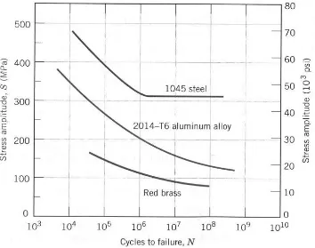
Most fatigue tests are conducted at what is referred to as “Constant Amplitude” which merely refers to the fact that maximum and minimum stresses are constant for each test cycle. S-Nf refers to a plot Constant Amplitude Stress Level(S) versus the Number of Cycles to Failure (Nf).
[image:16.612.173.527.263.542.2]A prediction of failure for various stress levels can be made by studying the material’s S-Nf curve
Figure 1: Stress amplitude versus number of cycles to failure curves (Richard A. Flinn, 1995)
2.2 Yield stress
7 deform plastically. Prior to the yield point the material will deform elastically and will return to its original shape when the applied stress is remove. Any point further than the yield stress, then the material will deform plastically that means it will not return to its original shape, or break, or fracture in the process (Callister & Kethwisch 2010)
2.3 Ultimate tensile stress
8
2.4 Fatigue
2.4.1 Definition
The process of progressive localized permanent structural damage occurring in a material subjected to conditions that produce fluctuating stress and strain at some points and that may culminate in cracks or complete fracture after sufficient number of fluctuations (Liu 2005)
Fatigue is one of the principle damage mechanisms for materials operating at elevated temperatures. Fatigue at elevated temperature produces larger strain deformation, crack initiation and growth for the material under elevated fatigue, there is serious influence on the properties and fatigue life of the material (Mao & Mahadevan 2000)
2.4.2 Nature of Fatigue
Fatigue failure resulted from simultaneous action of cyclic stress, tensile stress and plastic strain. The crack will not initiate and propagates if there is none of these stress and strain.
Fatigue can be stress based, strain based, and fracture mechanics based (Liu 2005). Plastic strain initiates the cracks; while the tensile stress promotes crack growth (propagation).
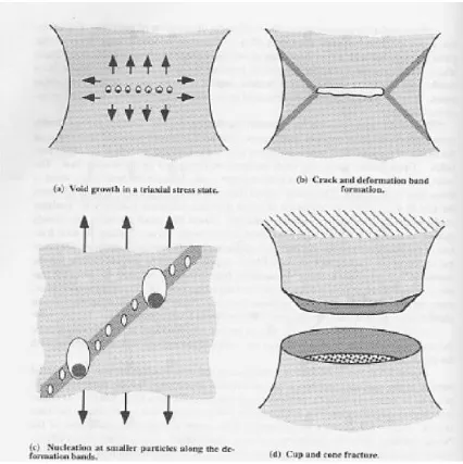
9 2.4.3 Fatigue under ambient and elevated temperature
When tested at ambient temperature and an elevated temperature of 190
0C, aluminium tensile behavior increases as the temperature increases. As the
[image:19.612.115.541.232.659.2]temperature is increased the atomic bonds are weakened as the atoms are energized (Leong 2008). This will result in the nucleation of micro inter-granular voids as shown in Figure 2.
11
CHAPTER 3
METHODOLOGY
3.1 Introduction
12
3.2 Specimen preparation
Specimen dimensions for fatigue specimen
Specimen design
Fabrication process
Raw material into 360mm long solid aluminium shaft
Center drilling at the ends of the specimen
Fabrication of designed specimen using CNC turning
machine ASTM 8M Scantool Bandsaw Machine Conventional Lathe Machine Run the specimen using CNC coding Specimen prepared
13
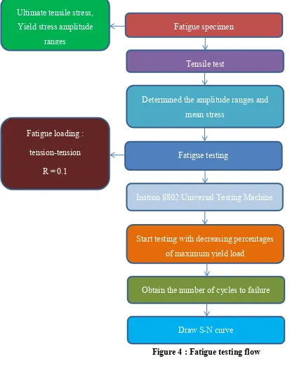
Fatigue specimen
Determined the amplitude ranges and mean stress
Tensile test
Fatigue testing
Instron 8802 Universal Testing Machine
Start testing with decreasing percentages of maximum yield load
Obtain the number of cycles to failure
Draw S-N curve Ultimate tensile stress,
Yield stress amplitude ranges
Fatigue loading :
tension-tension
[image:23.612.51.464.83.634.2]R = 0.1
14
3.3 Material specification
Fatigue material : Aluminium alloy Grade designation : AA6061-T6
Chemical composition : 95.8% Al, 0.35% Cr, 0.4% Cu, 0.7% Fe, 1.4% Mg, 0.15% Mn, 0.4% Si, 0.15% Ti, 0.25% Zn.
Tensile strength : 45000 psi ( 310 MPa) Yield strength : 40000 psi ( 276 MPa) Elongation : 12-17%
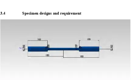
[image:24.612.112.543.361.625.2]3.4 Specimen designs and requirement