Volume 2013, Article ID 735981,10pages http://dx.doi.org/10.1155/2013/735981
Research Article
Magnesium Coated Bioresorbable Phosphate
Glass Fibres: Investigation of the Interface between
Fibre and Polyester Matrices
Xiaoling Liu, David M. Grant, Andrew J. Parsons, Lee T. Harper,
Chris D. Rudd, and Ifty Ahmed
Division of Materials, Mechanics and Structures, Faculty of Engineering, University of Nottingham, Nottingham NG7 2RD, UK
Correspondence should be addressed to Xiaoling Liu; [email protected]
Received 19 April 2013; Revised 22 July 2013; Accepted 22 July 2013
Academic Editor: Zbigniew Gugala
Copyright © 2013 Xiaoling Liu et al. This is an open access article distributed under the Creative Commons Attribution License, which permits unrestricted use, distribution, and reproduction in any medium, provided the original work is properly cited.
Bioresorbable phosphate glass fibre reinforced polyester composites have been investigated as replacement for some traditional metallic orthopaedic implants, such as bone fracture fixation plates. However, composites tested revealed loss of the interfacial integrity after immersion within aqueous media which resulted in rapid loss of mechanical properties. Physical modification of fibres to change fibre surface morphology has been shown to be an effective method to improve fibre and matrix adhesion in composites. In this study, biodegradable magnesium which would gradually degrade to Mg2+in the human body was deposited via magnetron sputtering onto bioresorbable phosphate glass fibres to obtain roughened fibre surfaces. Fibre surface morphology after coating was observed using scanning electron microscope (SEM). The roughness profile and crystalline texture of the coatings were determined via atomic force microscope (AFM) and X-ray diffraction (XRD) analysis, respectively. The roughness of the coatings was seen to increase from40 ± 1nm to80 ± 1nm. The mechanical properties (tensile strength and modulus) of fibre with coatings decreased with increased magnesium coating thickness.
1. Introduction
Bioresorbable polymers have shown great potential in ortho-paedic applications due to their advantages over traditional metals and alloys such as allowing gradual transfer of loads to the healing bone, in order to reduce or eliminate stress shielding effects and avoiding secondary surgery for removal
[1]. Stress shielding in bone repair applications occurs as
the result of the reduction of stress from the bone via use of an implant. A variety of resorbable polymers have been identified as suitable for clinical use in orthopaedics, such as the polyesters: polylactic acid (PLA), polyglycolic acid (PGA), polycaprolactone (PCL), and their copolymers. How-ever, the mechanical properties of these resorbable polymers are often insufficient especially for load bearing bone repair applications. As such reinforcing resorbable polymers is an attractive approach to overcome these limitations, which can be obtained via fabrication of fibre reinforced composites.
Bioresorbable phosphate glass fibre (PGF) reinforced polymer composites have attracted much interest, and researchers investigating these composites have indicated that the mechanical properties of these materials are
eas-ily tailored by adjusting their fibre volume fraction [2–4].
However, studiesin vitro have shown an initial rapid loss
of composite mechanical properties in the very early stages of immersion within aqueous media. This phenomenon is believed to be due to plasticisation of the matrix and degradation of the interface between the fibres and matrix
when exposed to an aqueous media [2–5].
The interface is crucial for the performance of the com-posites, and typically, interfacial adhesion can be improved by chemically linking the glass fibre and polymer or via
mechanical interlocking between the fibre and the matrix [6].
Methods used successfully to improve interfacial adhesion in glass fibre-reinforced polymers have involved coupling
polymerisation [12–15] of fibres. However, improving the interfacial strength in biodegradable systems has proved rather challenging due to the degrading nature of the mate-rials concerned. The phosphate glass fibre/PLA interface
studied by Haque et al. [16] found that the silane and
compatibilizing agent treatments on fibre the surface showed initial improvement in interfacial properties, but, revealed a decrease in properties to the same value as the control fibres after 3 days of immersion within deionised water.
CH4plasma treatment of a CaP fibre/PGA composite
stud-ied by Ibnabddjalil et al. [17] revealed a 30% increase in
interfacial shear strength; however, this decreased to even lower than the control fibres after immersion in phosphate buffered saline (PBS) for only a few hours. The treatments for PGF/polymer interface improvement as mentioned above rely on the chemical bond formed between fibre surface and the coupling agents or matrix. Additionally, as these composites are intended for implantation within the body, all coupling agents used must be biocompatible, which limits the selection.
Physical treatments can change the structural and surface properties of the fibre and thereby influence mechanical
bonding with the matrix [18]. To date, no physical
modifi-cation treatment has been investigated for the PGF/polymer composite system, whilst it has been used successfully in
carbon fibre reinforced composites [6]. The objective of
this study was to investigate improvement of the interfacial adhesion between PGF and polyester (polycaprolactone and polylactide) matrices through physical surface modification of the fibres.
Magnetron sputtering is a promising coating technique and has been widely used to fabricate thin metal nanos-tructured films with varying morphologies and roughness
[19]. For medical applications, magnetron sputtering has been
used for coating CaP/HA onto medical devices to create
a bioactive implant [20]. During the sputtering process,
target atoms are sputtered by ions and neutrals, and a thin film layer is formed on the substrate surface. The process does not require any solvents and can be conducted at near room temperature. Magnesium alloys have been used as degradable implants in the clinic since 1878 and show
good biocompatibility [21]. Previous studies on sputtered Mg
films, which were conducted mainly for hydrogen storage applications, have shown that thin nanocrystalline Mg films
were formed exhibiting a rough morphology [22]. The surface
topography can easily be modified by adjusting the coating
conditions [23,24].
In this study, bioresorbable PGFs were coated with mag-nesium via magnetron sputtering, with the aim of modifying the PGF surface morphology to investigate improvement of the PGF/PLA or PGF/PCL interface. The crystalline textures and roughness profile of the coatings in this study were investigated using X-ray diffraction (XRD) and atomic force microscope (AFM), respectively, and coating morphologies were observed by scanning electron microscope (SEM). The effects of these coatings on the mechanical properties of PGFs were studied. The interfacial properties were investigated using single fibre fragmentation tests to examine the effects
of physical modification using PGF/PLA or PCL single fibre composites.
2. Materials and Methodology
2.1. Phosphate Glass and Fibres Production. Sodium
dihydro-gen phosphate (Na2HPO4), calcium hydrogen phosphate
(CaHPO4), phosphorous pentoxide (P2O5), magnesium
hydrogen phosphate trihydrate (MgHPO4⋅3H2O), and iron
phosphate dihydrate (FeHPO4⋅2H2O) precursors
(Sigma-Aldrich, UK) were used without further purification. The precursors were weighed according to the composition
45% P2O5—16% CaO—24% MgO—11% Na2O—4% Fe2O3
(mol%), and the mixture was placed into a Pt-5% Au crucible type BC18 (Birmingham Metal Company, UK) and dried in
at 350∘C for 30 minutes, before being transferred to another
furnace at 1100∘C for 90 minutes. The molten glass was then
poured onto a steel plate and left to cool to room temperature.
Phosphate glass fibres (PGFs) (ca. 26𝜇m in diameter)
were manufactured via a melt-draw spinning process using an
in-house built fibre drawing facility [25]. Pulling temperature
and speed were adjusted to ca. 1250∘C and ca. 1060 rpm.
Both glass and glass fibres produced were kept in a desiccator before use.
2.2. Deposition of Magnesium Thin Films. Both glass slides (Fisher Scientific, UK) used for analysis and glass fibres were subjected to magnetron sputtering for the deposition of magnesium films. Samples were loaded onto a spindle shaped sample holder and placed into a magnetron sputtering rig with two circular superVac magnesium targets (76.2 mm, 99.99%, Testbourne Ltd, UK); one was placed above and one below the fibre samples. The sample holder rotated at a speed of 2 rpm. The nearest distance of the target to glass/fibre is 62 mm; the farthest distance is 128 cm. Magnesium thin films were deposited by sputtering these magnesium targets in an argon atmosphere using a DC magnetron system at 30 W.
The system vacuum was 7 × 10⁻⁶mbar, and the working
pressure was3.3 × 10−3mbar. The target surface was cleaned
prior to deposition by presputtering for 10 minutes at 30 W. Coating times of 10, 30, 60, and 120 minutes were investigated.
The coating thickness was 0.8𝜇m, 2𝜇m, 4𝜇m, and 9.5𝜇m,
respectively.
2.3. Characterisation of Magnesium Films. Film thicknesses were confirmed using a Philips JEOL XL30 scanning electron microscope (SEM) at an accelerating voltage of 20 kV. The roughness of the films deposited was obtained using Atomic Force Microscopy (AFM) in tapping mode. Magnesium distribution on the fibre surface was measured using Energy Dispersive X-ray (EDX) via mapping scans of the cross-sectional area of fibre. The crystal structure of the films was examined via X-ray diffraction performed on a D500
diffrac-tometer using CuK𝛼radiation (𝜆 = 0.154nm), operating at
40 kV and 25 mA with a step size of 0.02∘and dwell time of
a function of coating time were calculated using the following formula:
𝑇𝑐 = 𝐼𝑚(ℎ𝑘𝑙) /𝐼0(ℎ𝑘𝑙)
(1/𝑛) ∑𝑛1𝐼𝑚(ℎ𝑘𝑙) /𝐼0(ℎ𝑘𝑙), (1)
where 𝐼𝑚(ℎ𝑘𝑙) is the measured relative intensity of the
reflection from the(ℎ𝑘𝑙)plane,𝐼0(ℎ𝑘𝑙)is the relative intensity
from the same plane in a standard reference sample, and
𝑛is the total number of reflection peaks from coating. The
grain size of the deposited Mg films was estimated from the following Scherrer formula:
𝐷 = 0.9𝜆
𝐵cos𝜃, (2)
where𝐵is the corrected fullwidth at half maximum (FWHM)
of a Bragg Peak,𝜆is the X-ray wavelength, and𝜃is the Bragg
angle.
2.4. Characterisation of Coated Fibres
2.4.1. Fibre Tensile Properties. Fibre tensile properties were measured using a sensitive linear tensile test facility (LEX810, Diastron Ltd, Japan) coupled with a laser diameter gauge (Mutitoyo Series 544 LSM-500S). The crosshead speed of the machine was 1 mm/min, and the load cell capacity was 2000 N. A minimum of 20 samples were tested, and the Weibull parameters of the fibre tensile properties were calculated using Minitab 16 (version 16.2.2).
2.4.2. Interfacial Shear Strength (IFSS) Measurement. Two types of matrix, polylactide (PLA, 6201D NatureWorks Mw 90,000–120,000) and polycaprolactone (PCL, 181609 Sigma-Aldrich Mw ca. 65,000), were used in this study. The interfacial shear strength (IFSS) between fibre and (PCL or PLA) matrix was measured via the single fibre fragmentation test (SFFT). Single glass fibres were embedded between
80 × 20mm films of polymer and then hot pressed (120∘C
for PCL matrix, 210∘C for PLA matrix) at 10 bar for 10
minutes to make 0.25 mm thick single fibre composites. The
single fibre composites were cut into65 × 10 × 0.25 (𝑙 ×
𝑏 × ℎ) mm shaped specimens. These
dog-bone-shaped specimens were loaded axially in a tensile testing machine (Hounsfield series S testing machine, UK) using a
1 kN load cell and a crosshead speed of 1 mm min−1. After
tensile testing, the specimens were observed under an optical microscope (Nikon Optiphot, Japan) in order to ascertain the number of fibre fragments generated. The Kelly-Tyson model
[26] was then used to calculate the IFSS values:
𝜏 = 𝜎𝑓𝑑
2𝑙𝑐 , (3)
where𝜏is the IFSS value,𝑑is the fibre diameter, and𝜎𝑓is the
fibre strength at a length equal to the critical fibre length𝑙𝑐.
The critical fibre length (𝑙𝑐) was calculated by
𝑙𝑐= 43𝑙,
𝑙 = 𝑙0
𝑁,
(4)
where𝑙is the average fragment length,𝑙0is the gauge length,
and𝑁is the number of fibre fragments.
Fibre strength, 𝜎𝑓, can be calculated from the Weibull
distribution as follows [27]:
𝜎0
𝜎𝑓 = (
𝑙𝑐
𝑙0)
1/𝑚
, (5)
where𝜎0is the fibre strength at a particular gauge length𝑙0
and𝑚is the Weibull modulus (in this study the gauge length
investigated was 25 mm).
2.4.3. Statistical Analysis. Statistical analysis was performed using the Prism software package (version 3.02, GraphPad
Software, San Diego, CA, USA,http://www.graphpad.com/).
A one-way analysis of variance was calculated with the Tukey
multiple comparison posttest (𝑃 < 0.05) to compare the
significance of change in one factor at one time point.
3. Results
3.1. Magnesium Film Characterisation
3.1.1. Film Thickness and Roughness. Initially, thin magne-sium films were deposited onto flat microscope glass slides in order to investigate their thickness and roughness features. The film thickness was measured from the cross-sectional view of the micrographs obtained. Representative transverse section images of the magnesium films deposited onto glass
slides are presented in Figures 1(a) and 1(b) and revealed
columnar growth structures. A linear increase in Mg film
thickness from 0.8𝜇m to 9.5𝜇m with coating time (from 10
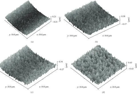
to 120 minutes) was shown inFigure 2. Film roughness
mea-sured by AFM was also observed to increase from40 ± 1nm
to80 ± 1nm with increased coating time (3D topographical
images obtained for magnesium films are shown inFigure 3).
3.1.2. Crystalline Structure. XRD profiles for magnesium
films deposited at 30 W are shown in Figure 4. A
crys-talline magnesium phase was identified for all the samples investigated (ICDD patent PDF-2 database File number 00-035-0821) with peaks observed at 2-theta values of 34.40,
47.83, 63.06, and 81.50.Figure 4exhibited a (002) preferred
orientation during the initial coating which then changed to a mixed orientation with more (102) orientation after 120 min
coating. From the calculated texture coefficients,Figure 5, it
was seen that the (002) orientation decreased with coating time, whereas the (102) and (103) orientations were seen to increase with coating time.
3.2. Characterisation of Magnesium Film Deposition on Phosphate Glass Fibres
3.2.1. Fibre Surface Morphology and Element Analysis. Phos-phate glass fibres (PGF) were sputter coated with pure magnesium for 10, 30, 60, and 120 min. Sample surface morphologies observed under SEM are presented in Figures
(a) (b)
Figure 1: Transverse view of magnesium film deposition onto a glass slide after coating at 30 w for 120 min.
0 0.8
2 4
9.5
40 44
61.4
80.4
0 10 20 30 40 50 60 70 80 90 100
0 2 4 6 8 10 12
0
50 100 150
Thickness Roughness
Ro
ug
hness (nm)
Coating time (min)
y = 0.0762x
y = 0.3816x + 35.462
Thic
kness (
𝜇
m)
(a)
0 20 40 60 80 100
0 2 4 6 8 10 12
Ro
ug
hness (nm) y = 4.706x + 37.273
Thickness (𝜇m)
(b)
Figure 2: (a) Magnesium coating thickness and roughness variation with coating time, (b) the coating roughness variation with coating thickness.
a roughened surface morphology using a plasma sputter-ing process. Magnesium films deposited over time on the fibre surface showed separated granular morphologies in comparison with the continuous coatings observed on the
glass slides (see Figure 1). It was seen that rougher films
(compared with pristine fibre inFigure 6(a)) were created on
the fibre surface with increased coating time which correlated well with the observations made for the coated glass slides (Section 3.1.1).
Magnesium coated fibres were then embedded in casting resin and polished to observe their cross-sectional view. As
seen inFigure 7(a), the fibres had an outer Mg coating layer
that was clearly visible using backscattered SEM imaging. EDX analysis in mapping mode gave a clearer view of the magnesium distribution on the fibre cross-sectional area (see Figure 7(b)). A continuous magnesium coating was observed on the fibre periphery which was easily distinguished from the Mg contained within the glass formulation (seen as speckles within the white outer ring). The fibres were held at a radius of 33 mm from a rotating spindle such that the side of the fibre that faced the target was closer to the two targets, while the other side was 66 mm further away resulting in the observed variation of thickness.
3.2.2. Fibre Mechanical Properties. PGFs before and after coating were measured by single fibre tensile test. Tensile
strength obtained decreased from 569 ± 46MPa to 463 ±
15MPa, whilst, the modulus decreased from 57 ± 1GPa
to48 ± 0.2GPa after 10 min coating (Mg coating thickness
0.8𝜇m). Further reduction of properties was observed with
increased coating time (seeFigure 8). Fibre tensile strength
decreased by57%± 6% after 120 min coating, whilst tensile
modulus decreased by38%± 2%.
3.2.3. Interfacial Shear Strength Test. The single fibre frag-mentation test (SFFT) was used to investigate the interfacial properties between fibres and matrix. The constant shear
model of Kelly and Tyson was used to calculate IFSS [26].
The validity of the Kelly and Tyson model for the calculation of IFSS from the fragmentation (SFFT) test requires that the
samples are fully saturated with fragments [28]. Thus, before
calculating IFSS with SFFT data, the numbers of fragments obtained were checked for full saturation using as received phosphate glass fibres.
[image:4.600.83.519.241.425.2]0.21
−0.21 (𝜇m)
y:10.0 𝜇m x: 10.0 𝜇m
(a)
(
𝜇
m)
0.30
−0.17
y:10.0 𝜇m x: 10.0 𝜇m
(b)
(
𝜇
m)
0.34
−0.27
y:10.0 𝜇m x: 10.0 𝜇m
(c)
(
𝜇
m)
0.43
−0.43
y:10.0 𝜇m x: 10.0 𝜇m
[image:5.600.64.544.73.404.2](d)
Figure 3: AFM of magnesium films deposited on glass slides at 30 W for (a) 10 min, (b) 30 min, (c) 60 min, and (d) 120 min.
20 30 40 50 60 70 80 90
Int
en
sit
y
2𝜃
10 min 30 min 60 min 120 min
Mg (002) Mg (102)
Mg (101)
Mg (103)
[image:5.600.61.283.448.602.2]Mg (004) Mg (104)
Figure 4: XRD of magnesium films deposited at 30 W.
fragments obtained versus strain are shown in Figures9(a)
and 9(b). For the PLA single fibre composite samples, the
number of fragments was seen to increase with increasing
strain (Figure 9(a)). Increasing the strain further past 4.5%
resulted in failure of the PLA matrix. However, the number of fragments increased with increasing strain and reached a
plateau after 10% for PCL based samples (seeFigure 9(b)).
This observation confirmed that full saturation of fragments
0 0.5 1 1.5 2 2.5 3 3.5 4
10 30 60 120
(002) (101)
(102) (103)
T
ext
ur
e co
efficien
t
Coating time (min)
Figure 5: Texture coefficients of magnesium films deposited at 30 W. The dotted line represents the value of a randomly oriented sample.
was achieved using PCL, thus PLA was not used for further investigations.
As fibre strength was seen to decrease after magnesium
coating (Figure 8), the Weibull parameters (shape and scale)
[image:5.600.315.541.452.596.2](a) (b) (c)
[image:6.600.81.519.71.326.2](d) (e)
Figure 6: SEM of magnesium coated fibres with (a) pristine fibre, (b) 10 min, (c) 30 min, (d) 60 min, and (e) 120 min coating.
(a) (b)
Figure 7: (a) SEM cross-sectional view of Mg coated fibre, (b) magnesium distribution observed using EDX in mapping mode.
(10, 30, 60, and 120 min) fibres were 490.1, 405.3, 371.8, and 264.5, respectively. Whilst the Weibull shape values obtained were 8.3, 5.6, 4.6, and 4.6, respectively. Utilising these Weibull parameters, the IFSS values calculated for the
magnesium coated fibres are shown inFigure 10. The highest
value achieved was approximately8.9±1MPa obtained for the
4𝜇m Mg coated samples. From one-way ANOVA analysis,
significant difference was observed from 2𝜇m (𝑃 < 0.05) and
4𝜇m (𝑃 < 0.001) coating as compared with the control single
fibre composite.
4. Discussion
In this study, bioresorbable PGFs were coated with degrad-able magnesium via magnetron sputtering to try and create a rougher fibre surface in order to initiate a mechanical
interlock between the fibre and matrix, thus improving the composite interfacial properties. The roughness and thickness of these deposited magnesium films were seen to increase linearly with increasing coating time as shown inFigure 2(a). Figure 2(b)shows that the roughness varies with thickness over this range of 40–80 nm. This is typical
of sputtered coatings [23]. The coatings columnar structure,
[image:6.600.145.458.365.508.2]0 10 20 30 40 50 60 70 80 0 200 400 600 800 1000
0 2 4 6 8 10 12
Tensile strength Tensile modulus T ens il e st re ng th ( M P a) T en sile mo d u lu s (GP a)
[image:7.600.54.287.72.245.2]Coating thickness (𝜇m)
Figure 8: Mechanical properties of control fibre and coated fibres measured via the single fibre tensile test.
the incidence angle varies at any one spot on the fibre with time unlike a flat substrate in which the incidence angle would be constant. It has been shown that the angle of incidence of a substrate to a sputtered magnesium target strongly influences the preferred crystal growth direction.
St¨ormer et al. [29] studied Mg coating on a silicon wafer
with varied deposition angle from 0∘ to 70∘. It was found
that the coating morphology was strongly depends on the deposition angle and argon pressure. Increased roughness of Mg coating with higher deposition angle was observed. In the experiment presented here the angle was constantly changing thus the preferred orientation was also changing resulting in less orientation specific coating, with a more granular appearance from above and disrupted boundaries between grains.
XRD analysis of the Mg films on the glass slides revealed a hexagonal closed packed (hcp) structure. A highly intense (002) orientation (at 34.40 2-theta) peak was observed, which was suggested to be due to the low surface energy
configu-ration corresponding to the (002) plane [23]. Competition
between strain energy and surface energy during film growth may also have contributed to changes in preferred orientation
during deposition [30]. The thickness increase of the coating
led to additional strain energy resulting in the (102) and (103) orientations dominating to reduce the total energy in the system. The difference in growth rates for the different crystal
planes created a roughened surface texture [31].
Mechanical testing of the fibres with coating (via single
fibre tensile tests) showed a significant reduction (𝑃 < 0.05)
in strength and modulus after coating with magnesium. The breaking force for Mg coated fibres versus coating thickness
seen in Figure 11showed a decrease of force during initial
coating which indicated that the fibres must have been dam-aged during the early stages of the coating process. According
to Griffith’s theory of brittle fracture [32], the strength of
glass fibres is related to the fine cracks or flaws on the fibre surface. When fibres are under tension, stress concentrates at these fine cracks, and the cracks propagate into brittle
fractures. During the coating process, magnesium atoms were sputtered towards the fibre surface at several hundred eV. It is suggested that this type of atomic bombardment may have created flaws on the fibre surface or potentially enlarged the already existing inherent flaws. Moreover, the thermal expansion coefficient for a phosphate glass with a formulation similar to the one used in this study has been reported as
12 × 10−6K−1 [33], whilst for pure magnesium a thermal
expansion coefficient of28.4 × 10−6K−1 [34] was reported.
As such, this difference in thermal expansion coefficients may have contributed additional stress concentrations during the coating process, as heat produced within the chamber during the sputtering process may have resulted in contraction of the Mg coating more so than the fibre upon cooling. This could have placed the fibre surface under compression and the internal fibre under tension leading to the fibre being more susceptible to cracking and ultimately resulting in a
decrease of the properties as observed [35].
It was suggested that flaws were created on the fibre surface during the early stages of coating which resulted in the mechanical property decrease. Once the coating had reached a certain thickness, the decreasing mechanical properties were due to Mg deposition, as Mg has lower mechanical properties than phosphate glass fibre. Bulk Mg has a mod-ulus of 45 GPa. However, the sputtered Mg coating in this study contained voids, thus the mechanical properties were expected to be even lower.
Characterisation of the interfacial properties between the fibre and matrix was conducted using the single fibre
fragmentation test (SFFT) and Kelly Tyson model [26]. In
order to use the Kelly Tyson model, the fibre fragments of the samples should be fully saturated before failure of the matrix. In addition, as a general guideline, in this model the strain required for saturation should be at least three times the
fibre failure strain. However, a study by Netravali et al. [36]
observed that the strain required for saturation depended on the ductility of the embedding resin. Thus, in this study, two bioresorbable polymer matrices (PLA and PCL) were chosen as matrix and investigated. Single fibre composites of PGF/PLA and PGF/PCL were prepared and tensile tested at varying strains to investigate saturation effects. The max-imum critical strain obtained using PLA was approximately 4.5% due to its intrinsic brittle nature. Further strain resulted in matrix failure before saturation with fibre fragments had occurred. However, using PCL strain limits of approximately 15% was obtained, due to the ductile properties of PCL. As
seen fromFigure 9, a plateau in fibre fragments was seen at
10% strain for PCL. This result revealed that the SFFT was not suitable for the PGF/PLA system (using NatureWorks 6201D PLA) in order to determine the IFSS value. Thus, only the SFFT using the PGF/PCL system was deemed suitable from which to calculate IFSS.
From the interfacial studies conducted, an increase in
IFSS properties was seen with an increase in 4𝜇m thick Mg
coated PGF using the PGF/PCL system. Significant increase
was seen in 2𝜇m and 4𝜇m coating, which resulted in a
0 5 10 15 20 25 30 35 40
0 0.01 0.02 0.03 0.04 0.05
N
u
m
b
er o
f f
ragmen
ts
Strain
Number of fragments versus strain—PGFs/PLA
(a)
N
u
m
b
er o
f f
ragmen
ts
0 2 4 6 8 10 12
0 0.02 0.04 0.06 0.08 0.1 0.12 0.14 0.16 Strain
Number of fragments versus strain—PGFs/PCL
[image:8.600.68.533.72.238.2](b)
Figure 9: Number of fragments versus strain for (a) PGF/PLA and (b) PGF/PCL single fibre composites.
5.2 6.0
7.7
8.9
5.1
0.0 2.0 4.0 6.0 8.0 10.0 12.0
0 0.8 2 4 9.5
IFSS (MP
a)
∗
∗∗∗
[image:8.600.61.283.292.427.2]Coating thickness (𝜇m)
Figure 10: Comparison of IFSS value of control fibre and coated fibres measured by single fibre fragmentation test (the star symbols show significance value: one star (∗) for𝑃 < 0.05and three (∗∗∗) for
𝑃 < 0.001).
0.45
0.4 0.35 0.3 0.25 0.2 0.15 0.1 0.05 0
0 2 4 6 8 10
F
o
rce (N)
Coating thickness (𝜇m)
Figure 11: The breaking force for Mg coated fibres versus coating thickness.
creating a stronger interlock with the polymer matrix. Studies
by Lin et al. [6] showed a 110% increase in interfacial
strength for ZnO nanowire coated carbon fibre which was suggested to be due to the ZnO nanowires penetrating the epoxy matrix creating a strong interlock, and further
modification of the nanowire dimensions resulted in the
interfacial strength increasing by up to 228% [37]. In addition,
an increase in surface area (as evidenced by increasing surface roughness) at the fibre surface would also have contributed to enhancing the fibre and matrix contact. The IFSS value was seen to decrease to a similar value as the control for
the (longer) 120 min coating time (9.5𝜇m coating) which
indicated that another mechanism dominates, such as the energy of bombardment due to the Mg deposition and/or the elevated temperature in the chamber deteriorating the fibre properties.
The work presented here showed that a roughened fibre surface increased the IFSS properties of a single fibre com-posite; however, the effect of coating parameters on the fibre surface (especially regarding the type of bonding between the coating and fibre surface) requires further investigation. In addition, prevention of possible damage to the fibres during the coating process also needs to be explored.
5. Conclusions
Magnesium thin films were deposited onto glass slides and bioresorbable phosphate glass fibres using magnetron sputtering. Four different coating times were investigated, and both roughness and thickness were seen to increase with increased coating time. Mg coating thicknesses of 0.8–
9.5𝜇m were deposited on the phosphate glass fibre surface.
A columnar structure was observed for the magnesium coating, and crystalline phases of magnesium were detected,
with growth preferred in the (002) orientation in 0.8𝜇m
coating gradually changed to mixed orientations in (002),
(102), and (103) planes with 9.5𝜇m coating. The coated fibre
[image:8.600.54.288.499.633.2]magnesium coating. A statistically significant increase in IFSS
was seen with 2 and 4𝜇m magnesium coating (𝑃 < 0.05).
Whilst, it was found that PGF/PLA (NatureWorks 6201D) single fibre composites had insufficient strain for single fibre fragmentation testing. Future investigations will focus on the prevention of damage to the fibre mechanical properties during the coating process.
Conflict of Interests
None of the authors have any financial or other link to Birmingham Metal Company (UK), Sigma-Aldrich (UK), Testbourne Ltd (UK), Fisher Scientific (UK), Diastron Ltd (Japan), NatureWorks LLC (USA), Hounsfield (UK), or Nikon (Japan) that could be considered a conflict of interests. The names of the companies are listed with the materials or equipment that they provided, as is common practice in journal publications to ensure transparency/reproducibility.
Acknowledgments
The authors would like to acknowledge the financial support of the China Scholarship Council and the Engineering Faculty Research Funding, University of Nottingham.
References
[1] Y. Shikinami and M. Okuno, “Bioresorbable devices made of forged composites of hydroxyapatite (HA) particles and poly-L-lactide (PLLA)—part I. Basic characteristics,”Biomaterials, vol. 20, no. 9, pp. 859–877, 1999.
[2] I. Ahmed, I. A. Jones, A. J. Parsons et al., “Composites for bone repair: phosphate glass fibre reinforced PLA with varying fibre architecture,”Journal of Materials Science, vol. 22, no. 8, pp. 1825–1834, 2011.
[3] R. M. Felfel, I. Ahmed, A. J. Parsons, G. S. Walker, and C. D. Rudd, “In vitro degradation, flexural, compressive and shear properties of fully bioresorbable composite rods,”Journal of the
Mechanical Behavior of Biomedical Materials, vol. 4, no. 7, pp.
1462–1472, 2011.
[4] I. Ahmed, P. S. Cronin, E. A. Neel, A. J. Parsons, J. C. Knowles, and C. D. Rudd, “Retention of mechanical properties and cytocompatibility of a phosphate-based glass fiber/polylactic acid composite,”Journal of Biomedical Materials Research Part B, vol. 89, no. 1, pp. 18–27, 2009.
[5] A. J. Parsons, I. Ahmed, P. Haque et al., “Phosphate glass fibre composites for bone repair,”Journal of Bionic Engineering, vol. 6, no. 4, pp. 318–323, 2009.
[6] Y. Lin, G. Ehlert, and H. A. Sodano, “Increased interface strength in carbon fiber composites through a ZnO nanowire interphase,”Advanced Functional Materials, vol. 19, no. 16, pp. 2654–2660, 2009.
[7] A. T. DiBenedetto, “Tailoring of interfaces in glass fiber rein-forced polymer composites: a review,” Materials Science and
Engineering A, vol. 302, no. 1, pp. 74–82, 2001.
[8] C. Varga, N. Miskolczi, L. Bartha, and G. Lip´oczi, “Improving the mechanical properties of glass-fibre-reinforced polyester composites by modification of fibre surface,” Materials and
Design, vol. 31, no. 1, pp. 185–193, 2010.
[9] J. F. Feller and Y. Grohens, “Coupling ability of silane grafted poly(propene) at glass fibers/poly(propene) interface,”
Compos-ites Part A, vol. 35, no. 1, pp. 1–10, 2004.
[10] V. Cech, R. Prikryl, R. Balkova, A. Grycova, and J. Vanek, “Plasma surface treatment and modification of glass fibers,”
Composites Part A, vol. 33, no. 10, pp. 1367–1372, 2002.
[11] K.-B. Lim and D.-C. Lee, “Surface modification of glass and glass fibres by plasma surface treatment,”Surface and Interface
Analysis, vol. 36, no. 3, pp. 254–258, 2004.
[12] D. J. Marks and F. R. Jones, “Plasma polymerised coatings for engineered interfaces for enhanced composite performance,”
Composites Part A, vol. 33, no. 10, pp. 1293–1302, 2002.
[13] D. C¸ ¨okeliler, S. Erkut, J. Zemek, H. Biederman, and M. Mutlu, “Modification of glass fibers to improve reinforcement: a plasma polymerization technique,”Dental Materials, vol. 23, no. 3, pp. 335–342, 2007.
[14] K. Sever, M. Sarikanat, Y. Seki, H. A. G¨ulec, M. Mutlu, and I. H. Tavman, “Improvement of interfacial adhesion of glass fiber/epoxy composite by using plasma polymerized glass fibers,”Journal of Adhesion, vol. 86, no. 9, pp. 913–936, 2010. [15] V. Cech, R. Prikryl, R. Balkova, A. Grycova, and J. Vanek,
“Plasma surface treatment and modification of glass fibers,”
Composites Part A, vol. 33, no. 10, pp. 1367–1372, 2002.
[16] P. Haque, I. A. Barker, A. Parsons et al., “Influence of compati-bilizing agent molecular structure on the mechanical properties of phosphate glass fiber-reinforced PLA composites,”Journal of
Polymer Science A, vol. 48, no. 14, pp. 3082–3094, 2010.
[17] M. Ibnabddjalil, I.-H. Loh, C. C. Chu, N. Blumenthal, H. Alexander, and D. Turner, “Effect of surface plasma treatment on the chemical, physical, morphological, and mechanical properties of totally absorbable bone internal fixation devices,”
Journal of Biomedical Materials Research, vol. 28, no. 3, pp. 289–
301, 1994.
[18] J. George, M. S. Sreekala, and S. Thomas, “A review on interface modification and characterization of natural fiber reinforced plastic composites,”Polymer Engineering and Science, vol. 41, no. 9, pp. 1471–1485, 2001.
[19] F. Ruffino, V. Torrisi, G. Marletta, and M. G. Grimaldi, “Growth morphology of nanoscale sputter-deposited Au films on amor-phous soft polymeric substrates,”Applied Physics A, vol. 103, no. 4, pp. 939–949, 2011.
[20] W. J. Lo, D. M. Grant, M. D. Ball, B. S. Welsh, S. M. How-dle, E. N. Antonov et al., “Physical, chemical, and biological characterization of pulsed laser deposited and plasma sputtered hydroxyapatite thin films on titanium alloy,”Journal of
Biomed-ical Materials Research, vol. 50, pp. 536–545, 2000.
[21] F. Witte, “The history of biodegradable magnesium implants: a review,”Acta Biomaterialia, vol. 6, no. 5, pp. 1680–1692, 2010. [22] F. Mehmet, F.W. Cansizoglu, I. Pei-Wang, and T. Karabacak,
“Evolution of crystal orientation in obliquely deposited Mg nanorod arrays for hydrogen storage applications,”MRS
Pro-ceedings, vol. 1042, 2007.
[23] Y. K. Gautam, A. K. Chawla, V. Chawla, R. D. Agrawal, and R. Chandra, “Influence of sputtering gas on morphological and optical properties of magnesium films,” Journal of Materials
Science and Technology, vol. 27, no. 1, pp. 51–58, 2011.
[25] I. Ahmed, A. J. Parsons, G. Palmer, J. C. Knowles, G. S. Walker, and C. D. Rudd, “Weight loss, ion release and initial mechanical properties of a binary calcium phosphate glass fibre/PCL composite,”Acta Biomaterialia, vol. 4, no. 5, pp. 1307–1314, 2008. [26] A. Kelly and W. R. Tyson, “Tensile properties of fibre-reinforced metals: copper/tungsten and copper/molybdenum,”Journal of
the Mechanics and Physics of Solids, vol. 13, no. 6, pp. 329–338,
1965.
[27] D. Tripathi, T. Turton, F. Chen, and F. R. Jones, “A new method to normalize the effect of matrix properties on the value of interfacial shear strength obtained from the fragmentation test,”
Journal of Materials Science, vol. 32, no. 18, pp. 4759–4765, 1997.
[28] D. Tripathi, F. Chen, and F. R. Jones, “The effect of matrix yield strain on the data reduction technique of the single-filament fragmentation test,”Composites Part A, vol. 27, no. 9, pp. 709– 715, 1996.
[29] M. St¨ormer, C. Blawert, H. Hagen, V. Heitmann, and W. Dietzel, “Structure and corrosion of magnetron sputtered pure Mg films on silicon substrates,”Plasma Processes and Polymers, vol. 4, no. 1, pp. S557–S561, 2007.
[30] V. Chawla, R. Jayaganthan, and R. Chandra, “Structural char-acterizations of magnetron sputtered nanocrystalline TiN thin films,”Materials Characterization, vol. 59, no. 8, pp. 1015–1020, 2008.
[31] D. M. Mattox,Handbook of Physical Vapor Deposition (PVD)
Processing, William Andrew Publishing/Noyes, 1998.
[32] A. A. Griffith, “Phenomena of rupture and flow in solids,”ASM
Transactions Quarterly, vol. 61, pp. 871–906, 1968.
[33] S. Shaharuddin, Manufacture and Characterisation of Novel Resorbable Phosphate Based Glass Fibres for Biomedical
Appli-cations, University of Nottingham, Nottingham, UK, 2012.
[34] S. F. Hassan and M. Gupta, “Development of high performance magnesium nanocomposites using solidification processing route,”Materials Science and Technology, vol. 20, no. 11, pp. 1383– 1388, 2004.
[35] R. E. Cuthrell, D. M. Mattox, C. R. Peeples, P. L. Dreike, and K. P. Lamppa, “Residual-stress anisotropy, stress-control, and resistivity in post cathode magnetron sputter deposited molybdenum films,”Journal of Vacuum Science & Technology A, no. 6, pp. 2914–2920, 1988.
[36] A. N. Netravali, R. B. Henstenburg, S. L. Phoenix, and P. Schwartz, “Interfacial shear strength studies using the single-filament-composite test—I: experiments on graphite fibers in epoxy,”Polymer Composites, vol. 10, no. 4, pp. 226–241, 1989. [37] U. Galan, G. J. Ehlert, Y. R. Lin, and H. A. Sodano, “Effect
of morphology of ZnO nanowire arrays on interfacial shear strength in carbon fiber composites,”Functional Metal-Oxide
Submit your manuscripts at
http://www.hindawi.com
Scientifica
Hindawi Publishing Corporationhttp://www.hindawi.com Volume 2014
Hindawi Publishing Corporation
http://www.hindawi.com Volume 2014 Hindawi Publishing Corporation
http://www.hindawi.com Volume 2014
Hindawi Publishing Corporation
http://www.hindawi.com Volume 2014
Ceramics
Journal ofHindawi Publishing Corporation
http://www.hindawi.com Volume 2014
Nanoparticles
Journal ofHindawi Publishing Corporation
http://www.hindawi.com Volume 2014
Hindawi Publishing Corporation
http://www.hindawi.com Volume 2014 International Journal of
Biomaterials
Hindawi Publishing Corporation
http://www.hindawi.com Volume 2014
Nanoscience
Journal ofTextiles
Hindawi Publishing Corporation
http://www.hindawi.com Volume 2014
Journal of Hindawi Publishing Corporation
http://www.hindawi.com Volume 2014
Crystallography
Journal ofHindawi Publishing Corporation
http://www.hindawi.com Volume 2014
The Scientific
World Journal
Hindawi Publishing Corporationhttp://www.hindawi.com Volume 2014
Hindawi Publishing Corporation
http://www.hindawi.com Volume 2014
Coatings
Journal ofAdvances in
Materials Science and Engineering
Hindawi Publishing Corporation
http://www.hindawi.com Volume 2014
Hindawi Publishing Corporation
http://www.hindawi.com Volume 2014
Hindawi Publishing Corporation
http://www.hindawi.com Volume 2014
Metallurgy
Journal ofHindawi Publishing Corporation
http://www.hindawi.com Volume 2014
BioMed
Research International
Materials
Journal ofHindawi Publishing Corporation
http://www.hindawi.com Volume 2014
N
a
no
ma
te
ria
ls
Hindawi Publishing Corporation
http://www.hindawi.com Volume 2014
Journal of