Int. J. Electrochem. Sci., 11 (2016) 486 - 497
International Journal of
ELECTROCHEMICAL
SCIENCE
www.electrochemsci.org
Improving the Performance of a Graphite Electrode by Using
Polyaniline Coated Graphite and Its Application in Batch
Electrooxidation of Oxalic Acid
Y.A. Alhamed1, A.H. El-Shazly2,*, A.A. Al-Zahrani1, M.A. Daous1
1
Chemical and Materials Engineering Department, Faculty of Engineering, King Abdulaziz University, Jeddah, Saudi Arabia.
2
Chemical and Petrochemicals Engineering Department, Egypt-Japan University of Science and Technology, New Borg Elarab City, Alexandria, Egypt..
*
E-mail: [email protected]
Received: 31 August 2015 / Accepted: 27 October 2015 / Published: 1 December 2015
This work investigates the effect of electrolyte concentration (%NaCl) and organic loading (oxalic acid concentration) on the performance of a newly developed electrode of polyaniline coated graphite (PANG). The galvanostatic technique was used for building the new electrode under different aniline concentrations. The PANG electrode was characterized using different techniques such as FT-IR, XRD and SEM. The characterization results indicated that PANI was deposited on the graphite surface in the conductive form. The developed electrode was then investigated for its specific energy consumption and its kinetic performance in the electrooxidation of oxalic acid under different electrolyte concentrations (%NaCl) and different initial oxalic acid concentrations. The results showed that the PANG electrode is more efficient than the bare graphite electrode in both improving the reaction rate and increasing the energy efficiency of the process. The results showed that the mass transfer coefficient could be related to the concentrations of the different components by the relation: K= a CNaCl. Coxalic -0.556. The electrooxidation index (EOI) of the new PANG electrode was found to be much
higher than that of the bare graphite electrode by a factor ranging from 15 to 800% depending on the solution composition.
Keywords: Polyaniline, graphite electrode, electrooxidation, oxalic acid, wastewater treatment
1. INTRODUCTION
stable material against corrosion and a good catalysts for some electrochemical reactions [1-4]. Polyaniline (PANI), polypyrrole and other conducting polymers were proved and tested as active electrode materials in many applications, especially in fuel cells [5-8]. Patil et al [9] studied the chemical synthesis of highly stable polyvinyl alcohol (PVA)/polyaniline (PANI) films for super capacitor applications and found that the film is stable for more than 20,000 cycles. Patil et al [10] concluded that the composite electrode formed by activated carbon and PANI has a high specific capacitance and high energy density, which indicate a positive synergistic effect between the two materials.
Bleda-Martínez et al [11] found that the synthesis conditions strongly affect the electrochemical behavior of the produced composite of activated carbon/polyaniline. Potentiostatic polymerization was found to achieve the highest capacitance in the produced composite. The authors attributed this benefit to the enhanced electron delocalization along the polymer chains in the composites. Ma et al [12] found that polyaniline exhibited a significant promoting effect towards Pd for formic acid electrooxidation and concluded that the current densities of formic acid electrooxidation on the Pd catalysts with a PANI coating show a significant increase compared with that of the Pd reference catalyst without PANI as a promoter. The mass-specific activity (MSA) of Pd in 15PANI/Pd was 7.5 times that of the Pd catalyst. The enhanced performance of Pd catalysts is proposed as an electronic effect between Pd nanoparticles and PANI. Ficicioglu and Kadirgan [13] found that polyaniline films can be used as a convenient conducting substrate for the electrooxidation of ethylene glycol. In another study [14], the authors found that platinum doped polyaniline electrodes are promising for the direct oxidation of methanol, and the thickness of the polyaniline layer affected the rate of the reaction. A coated pyrolytic graphite electrode was found to exhibit a quick response time of 9 s and to perform satisfactorily over a wide pH range of 3.5-9. The sensor can work satisfactorily in water-acetonitrile and water-methanol mixtures [15]. This research investigates the method of preparation of a polymer modified graphite electrode by coating graphite with polyaniline electrochemically and its application in the electrooxidation of oxalic acid.
2. EXPERIMENTAL WORK
The experimental work was divided into two main parts: the development of the PANG electrode and the examination of the developed electrode in the electrooxidation of oxalic acid under different conditions.
2.1. Development of the PANG electrode
concentration, solution pH and time of reaction were kept constant at 20 mA/cm2, 0.3 M, 1.5 and 200s, respectively. After each experiment, the developed PANG electrode was rinsed with distilled water and methanol and left to dry. In all experiments, Ag/AgCl was used as the reference electrode, and a stainless steel sheet surrounding the graphite anode was used as the counter electrode. The formed PANI layer was characterized using different techniques such as FT-IR, SEM and XRD.
2.2. Examination of the developed PANG electrode in the electrooxidation of oxalic acid
The second part of this research is the examination of the developed PANG electrode in the electrooxidation of organic materials, represented by oxalic acid, in an electrochemical cell composed of the PANG electrode as the anode and a stainless steel cathode surrounding the PANG electrode. In this research, two main parameters were investigated for its effect on the electrooxidation reaction, namely, the electrolyte concentration (%NaCl) and the oxalic acid concentration. The rate of oxalic acid oxidation was determined by withdrawing 5 cm3 every 5 min for analysis by titration against standard permanganate solution [16].
The % removal of oxalic acid was calculated using the following equation:
(1)
where Co and Ct are the initial oxalic acid concentration and its concentration at any time t,
respectively.
3. RESULTS AND DISCUSSION 3.1. Development of the PANG electrode
In this stage, a layer of PANI has been successfully deposited on the surface of the graphite rod using the galvanostatic technique under different conditions of aniline concentrations, while other parameters such as current density, oxalic acid concentration, solution pH and time of reaction were kept constant at 20 mA/cm2, 0.3 M, 1.5 and 200s, respectively.
[image:3.596.183.414.581.730.2]
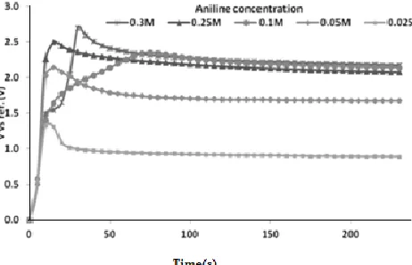
Figure 1 represents the results obtained during PANI layer formation on the graphite anode under different aniline monomer concentrations ranging from 0.025 to 3 M. The increased incubation period for PANI layer formation at higher aniline concentrations may be ascribed to the reduction in the diffusivity of aniline ions and the slow rate of transfer of the aniline ions at higher concentrations. The results also show that the cell potential increases by increasing the monomer concentration, which may be ascribed to the increased solution resistance due to the slow transfer of electrolyte ions and increased solution viscosity due to higher monomer concentration.
3.1.2. Characterization of the obtained PANI layer
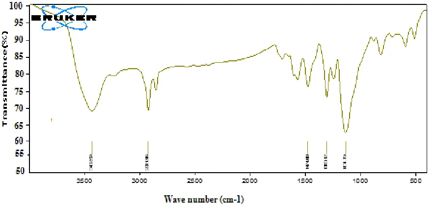
[image:4.596.75.518.495.706.2]Different characterization techniques such as FT-IR, SEM, and XRD were used for the characterization of the formed PANI layer. As shown in figure 2, the spectrum exhibits many peaks due to the structure of PANI. However, we are interested mainly in the peaks corresponding to quinonoid structure, benzenoid structure and C–H out-of-plane bending vibrations, which were assigned at 1480 (benzenoid form), 1570 (quinonoid form) and 800 (C-H out-of-plane bending vibration) cm-1 as shown. These results confirm that the produced PANI layer on the surface is of the conducting polyaniline structure, as it is neither fully oxidized (quinoid) nor fully reduced (benzenoid). Additionally, the peak at 3500 cm−1 is responsible for the N–H stretching of PANI. A peak at 2900 cm−1 accounts for the OH stretching of water molecules physisorbed by the PANI backbone. The XRD pattern of the PANG electrode is shown in figure 3. For PANI, the characteristic peaks appear at 15.3, 21.4 and 27, corresponding to the (011), (020) and (200) crystal planes of PANI [17]. The XRD pattern of graphite is known to have a diffraction peak at 2Ɵ=27, which is either to be overlapped with the peak of PANI or to result in the broad and intense peak in the composite.
Figure 3. XRD scan of the formed PANI layer on the graphite surface.
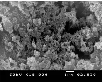
The data indicate that an additional crystalline order has been introduced into the structure by the new peak at 2Ɵ=29. Compared with graphite, the obvious characteristic peaks in PANG can be ascribed to the formation of crystal appearing on the outer layers of the graphite rod. This result shows that the PANI coating on the graphite is homogeneous, and the polymer matrix is well dispersed on the surface of the graphite rod, which can also be concluded from the SEM image in figure 4.
Figure 4. SEM scan of the formed PANI layer on the graphite surface.
3.2. Examination of the developed PANG electrode in the electrooxidation of oxalic acid
[image:5.596.135.462.359.622.2]
3.2.1. Effect of electrolyte concentration(%NaCl) 3.2.1.a. Electrolyte concentration vs kinetic data
The results, as shown in fig. 5, indicate that the % of oxidized oxalic acid is increased by increasing the NaCl concentration using either the PANG or bare graphite electrodes as anodes. The positive effect of NaCl on the electrochemical oxidation of oxalic acid can be explained by the fact that a series of chemical reactions will take place in the solution bulk starting with the chloride ion oxidation that leads to the formation of chlorine; chlorine, in turn, may react with either H2O or OH- to
form HOCl, which dissociates to OCl-, which can oxidize the oxalic acid [18,19]. The main reactions involved can be summarized in the following reactions:
(2)
(3)
Thus, increasing the available amount of NaCl will increase the produced hypochlorite and thus, increase the % of oxidized oxalic acid.
Figure 5. Percentage oxalic acid removal vs. time at different NaCl concentrations.
[image:6.596.135.431.338.504.2] [image:6.596.157.441.563.737.2]
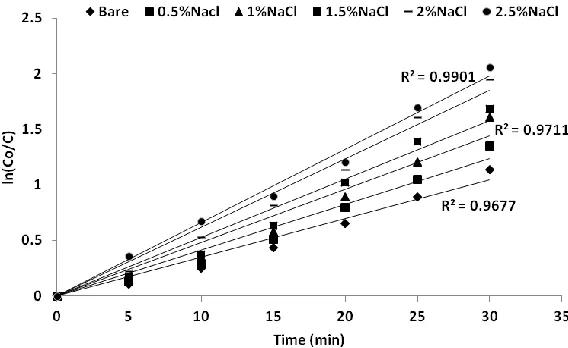
As shown in fig. 6, the kinetic evaluation of the process confirms that the electrooxidation of oxalic acid over graphite or PANG electrodes is of the first order kinetics, and the average R2 was calculated to be 0.975. The volumetric mass transfer coefficient K was calculated from the slope of the straight lines obtained by plotting ln(Co/C) vs t for different %NaCl. The results, as shown in fig. 7,
show that K is linearly proportional to the NaCl concentration.
Figure 7. K vs %NaCl for PANG electrode.
3.2.1.b. Electrolyte concentration vs. energy efficiency of the process
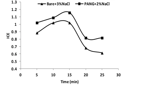
The instantaneous current efficiency (ICE) of the process was calculated using equation (4) [19]:
(4)
where Ct and Ct+∆t are the oxalic acid concentrations (g oxalic/dm3) at t and t+∆t, respectively; I
is the current (A); V is the electrolyte volume (dm3) and F is Faraday's constant (96487 C/mol).
0.4 0.5 0.6 0.7 0.8 0.9 1 1.1 1.2 1.3
0 5 10 15 20 25 30
IC
E
Time (min)
Bare+3%NaCl PANG+2%NaCl
[image:7.596.131.467.190.387.2] [image:7.596.174.420.597.745.2]
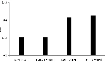
Figure 9. EOI for different electrodes at different NaCl concentrations.
For an energy efficiency comparison between the bare graphite and the developed PANG electrodes, the ICE was calculated for both electrodes in the presence of NaCl as electrolyte. The results show that the ICE for both has approximately the same performance with time. However, the ICE of the PANG electrode is higher than that of the bare graphite by approximately 15%. As shown in figure 8, the ICE increased to a higher value and then decreased with time for both electrodes. This behavior may be attributed to the higher amount of OCl- produced at the start of the process and then this amount decreases gradually with time. On the other hand, with time, some of the oxalic acid may be adsorbed on the electrode surface, which increases electrode polarization and decreases its efficiency.
From the ICE/t curve, the electrochemical oxidation index (EOI), which represents the average current efficiency of the electrochemical process under certain conditions, can be calculated as [19]:
(5)
where τ represents the time at which ICE approaches zero. Using figure 8, and from the equilibrium data, τ was assumed to be 60 minutes. Thus, the EOI was calculated under different conditions as shown in figure 9.
Fig. 9 shows that the EOI of the PANG electrode is higher than that of the bare graphite anodes even with higher NaCl concentrations. This result shows that the specific energy required by PANG electrodes is smaller than that required by the bare graphite electrode by approximately 17-17.5%, depending on the NaCl concentration for the electrochemical oxidation of oxalic acid.
3.2.2. Effect of oxalic acid concentration
3.2.1.a. Oxalic acid concentration vs. kinetic data
[image:8.596.195.410.74.202.2]
Figure 10. Percentage oxalic acid removal vs. time at different initial oxalic acid concentrations.
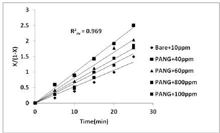
The kinetic data for the effect of initial oxalic acid concentration shows that the reaction kinetics do not fit first order kinetics, so the second order rate equation (6) was used
(6)
where X is the amount of oxidized oxalic acid, CAo is the initial oxalic acid concentration and t
is the reaction time. was plotted against t for different initial concentrations of oxalic acid, as shown in figure 11.
[image:9.596.77.515.437.702.2]
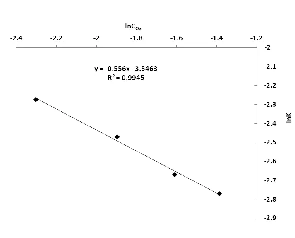
Figure 12. lnK vs lnCOx for electrooxidation of oxalic acid using the PANG electrode.
The rate constant was determined assuming the equation that:
K=αCOxn (6)
where COx is the oxalic acid concentration, and α and n are constants. Thus, by plotting lnK vs
lnCOx the value of n was found to be -0.556, as shown in fig. 12. Thus, the relation between K and COx
may be of the form:
K=αCOx-0.556 (7)
3.2.2.b. Oxalic acid concentration vs. energy efficiency of the process
[image:10.596.142.437.72.310.2]
Figure 13. ICE vs time at different electrode materials and different oxalic acid concentrations.
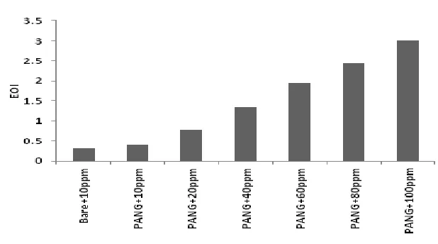
Figure 14. EOI for different electrodes at different initial oxalic acid concentrations.
4. CONCLUSIONS
An electrode of PANG was developed using the galvanostatic technique under different aniline concentrations. The PANG electrode was characterized using different techniques such as SEM, FT-IR and XRD. The characterization results indicate that PANI was deposited on the graphite surface in the conductive form. The developed electrode was investigated for its performance in the electrooxidation of oxalic acid under different solution compositions by changing the electrolyte concentration (%NaCl) and different initial oxalic acid concentrations. The results showed that the PANG electrode is more efficient than the bare graphite electrode in both improving the reaction rate and increasing the energy efficiency of the process. The mass transfer coefficient could be related to different component concentrations by the relation that:
[image:11.596.137.446.312.484.2]
The EOI of the new PANG electrode was found to be much higher than that of the bare graphite electrode by 800%, especially at higher oxalic acid concentrations.
ACKNOWLEDGEMENT
This project was funded by the National Plan for Science, Technology and Innovation (MAARIFAH)– King Abdulaziz City for Science and Technology-the Kingdom of Saudi Arabia–award number (12-ADV2760-03). The authors also acknowledge, with thanks, the Science and Technology Unit, King Abdulaziz University, for technical support.
References
1. M. Guerra-Balcázar, R.Ortega, F. Castaneda, L.G. Arriaga, J. Ledesma-Garcia, Int. J. Electrochem. Sci., 6 (2011) 4667 - 4675.
2. F. Yang, L. Ma, M. Gan, J. Zhang, J. Yan, H. Huang, L. Yu, Y. Li, C. Ge, H. Hu, Synth. Met. 205(2015)23-31.
3. B. Rajender, G. Ramesh, S. Palaniappan, Catalysis Commun.43(5)(2014)93-96. 4. A. H. El-Shazly, H. A. Al-Turaif, Int. J. Electrochem. Soc.,7(2012)5388-5399.
5. Y. Fang, Q. Jiang, M. Deng, Y. Tian, Q. Wen, M. Wang, J. Electroanal.Chem. 755(15)(2015)39-46. 6. C. Hui-Fang, D. Lin, G. Peng-Bo, Z. Bao, J.H.T. Luong, J. Power Sources 283 (2015)46-53. 7. L.Z. Pei, Z.Y. Cai, Y.K. Xie, D.G. Fu, Measurement, 53(2014)62-70.
8. D.S. Patil, S.A. Pawar, S.K. Patil, P.P. Salavi, S.S. Kolekar, R.S. Devan, Y.R. Ma, J.H. Kim, J.C. Shin, P.S. Patil, J. Alloys and Comp. 646(15)(2015)1089-1095
9. D. S Patil, J.S. Shaikh, D.S. Dalavi, S.S. Kalagi, P.S. Patil, Mater. Chem. Phys. 128, (3)(2011) 449-455.
10. D.S. Patil, S.A. Pawar, R.S. Devan, Y.R. Ma, W.R. Ba, J.H. Kim, P.S. Patil, Mater. Lett. 117(2014)248–251
11. M.J. Bleda-Martínez, C. Peng, S. Zhang, G.Z. Chen, E. Morallón and D. Cazorla-Amorósa, J. Electrochem. Soc. (155)(9)(2008)A672-A678.
12. X. Ma, Y. Feng, Y. Li, Y. Han, G. Lu, H. Yang, D. Kong, Chin. J. Catalys. (36)(7)(2015)943-951. 13. F. Ficicioglu , F. Kadirgan, J. Electroanal. Chem. 451(1998)95–99.
14. F. Ficicioglu , F. Kadirgan, J. Electroanal. Chem. 430(1997)179-182.
15. M. K. Sahani, A.K. Singh, A.K. Jain, Mater. Sci. Eng. C, 50(1)(2015)124-132. 16. A.A. Vogel, Text book of quantitative inorganic analysis. London: Longmans; 1961. 17. L. Ding, Q. Li, D. Zhou, H. Cui, H. An, J. Zhai, J. Electroanal. Chem. (668) (2012)44-50. 18. F. Bonfatti, A. Battisti, S. Ferro, G. Lodi, S. Osti, Electrochem. Acta. 46(2000)305-314. 19. Ch. Comninellis, A. Nerini, J. Appl. Electrochem. 25(1995)23-28.
20. N.A. Travlou, G.Z. Kyzas, N.K. Lazaridis, E.A. Deliyanni, Chem. Eng. J. 217(2013)256-265.