A Resource Management Architecture For Future Mobile
Communications Systems
R.C. Atkinson, J.M. Irvine & J. Dunlop
Mobile Communications Group
University of Strathclyde
Glasgow, UK, G1 1XW
[email protected]@[email protected]
ABSTRACT
This paper presents an overview of a hierarchical Re-source Management architecture for future mobile com-munications systems. The architecture is designed to be generic and can therefore be adopted for a range of Ra-dio Access Methodologies. In particular it provides a mechanism for radio resource management across air-interfaces such as those being defined for use with UMTS. Given the move towards packet-switched tech-nologies both in the Core Network and the Radio Access Network [1], the architecture embraces the concept of statistical QoS applied to individual flows in the form of a commitment level.
I. INTRODUCTION
The 3G cellular system UMTS has been designed to ac-commodate a number of different air-interfaces or Radio Access Methodologies including UMTS FDD, UMTS TDD, and GSM/EDGE. The distinct access methodolo-gies, however, operate largely in isolation. If they could be integrated such that they can be managed collectively, a number of potential benefits may be possible. The Re-source Management (RM) architecture that is the subject of this paper proposes a two level split in Radio RM (RRM) functionality. It defines access methodology-specific entities to manage radio resources on each air-interface, and a methodology-independent entity to man-age radio resources collectively across air-interfaces. With the drive towards packet-switching technologies first in the Core Network and latterly in the Radio Ac-cess Networks, much research has focussed on providing QoS on the bearers within the mobile networks. The RM architecture described proposes the assignment of a sta-tistical QoS parameter to individual flows within the mobile network. The parameter, known as a commitment level, indicates the degree to which the required QoS will be delivered by the network.
A high-level overview of the architecture is provided in Section 3 describing its potential benefits. Next, Section 4 presents a description of the logical RM entities and the interaction between them. Then Section 5 discusses what would be required to implement the architecture on a UMTS R99 system, thereby demonstrating its com-patibility with existing network architectures.
II. OVERVIEW OF RM ARCHITECTURE The RM architecture has two key characteristics:
• Two level radio resource management. The Radio Resource Manager (RRM) entity manages radio re-sources of particular air-interfaces. The Service Con-tract Manager (SCM) entity manages all radio re-sources across air-interfaces of a geographical area.
• Level of commitment for QoS request. Entities indi-cate which degree of confidence can be attributed to the QoS requirements of individual flows.
The two level split enables distinct flows 1 of an
individ-ual session to be carried over different access method-ologies, i.e. air-interfaces. It allows for co-ordinated RM in Hierarchical Cellular Structures (HCS) where all radio resources in a geographical area can be managed by a single SCM. The SCM can decide which calls (or flows) are most suited to particular HCS layers, e.g. high bit-rate service assigned to microcells, and the RRMs con-trol the radio bearers on each of the base stations, e.g. macro, micro, pico. This concept can also be extended to cover different access methodologies whereby the SCM can determine which air-interface is most appropriate for a flow. Furthermore, it may route the flows of a single call over different air-interfaces.
This division of responsibility allows the SCM to per-form traffic engineering function, e.g. traffic balancing. Furthermore, co-ordinated control of the diverse air-interfaces aids Mobility Management since the informa-tion pertaining to resource availability on different air-interfaces is available in one location. This facilitates inter-system handover which lessens call dropping prob-ability - an important QoS metric. Overall system capac-ity is also increased due to trunking gains resulting from the channel pooling of the various access methodologies. It is anticipated that a greater range of serv-ices/applications will be available to subscribers in fu-ture networks, the services will have diverse QoS re-quirements. The Wideband CDMA air-interface devel-oped for UMTS is designed to provide flexible band-width provision through the use of Orthogonal Variable Spreading Factor Codes. WCDMA therefore has the ability to support these new services through UMTS service negotiation. It is also anticipated that there will be a move from traditional circuit-switched operation towards packet-based networks. The move towards ad-vanced packet-based services (including circuit-switched
1 Within the context of this paper a flow is defined as a part of a
emulation) each with distinct QoS requirements, coupled with the flexible bandwidth provision over the air-interface gives rise to the requirement of flexible band-width provision within the mobile network itself, i.e. in the Radio Access Networks (RAN) and Core Network (CN). Thus, the bearers in a mobile network, including those between the CN and the air-interface, require some method of QoS specification.
The QoS requirements of users will be largely dependent on the service they require. Speech users may require some form of circuit-switched emulation, which pro-vides very tight bounds on the treatment of the flow to match latency and jitter requirements. Users requiring web access of file transfer facilities may be satisfied with a moderate QoS bounds whereby throughput and delay are within specified bounds. Other users may be satisfied with wide QoS bounds similar to ATM’s available bit-rate service whereby bandwidth is allocated to users when available, this type of service may be suitable for background download of emails etc. The QoS require-ments of these services could be specified statistically. Web applications could be offered, say, an average throughput of 64kbps over a given period of time as op-posed to a guaranteed constant throughput of 64kbps. Advanced MAC techniques may allow speech to be transported over the air-interface in packet form to take advantage of statistical multiplexing of users onto chan-nels which recognises that on average speech users are inactive more than 50% of the time. This would allow the QoS offered to speech traffic to be described statisti-cally, i.e. the delay perceived by the user will be within tight statistical bounds. This gives rise to assigning a statistical parameter to the QoS specification of network bearers. Therefore this architecture also introduces the concept of a commitment level. The commitment level is defined as the probability that the network will be able to meet the flow's specified QoS requirements on an ongo-ing basis without the need for re-negotiation. For exam-ple, for a speech flow it may be sufficient to state that the latency encountered by speech packets will be within prescribed bounds, say, 90% of the time. In this case a 90% commitment level is assigned to the flow – along with the associated bounds. Similarly for web traffic it may be sufficient to offer 64kbps over a given time pe-riod for only 80% of the time, i.e. an 80% commitment level is assigned to this type of flow.
Assigning a commitment level (i.e. a statistical measure) to a QoS request recognises that in a mobile network the characteristics of the radio link are statistical in nature; delay, throughput, and probability of error are deter-mined by the state of the radio channel. The challenge is to map the time-varying radio resource requirements of a flow onto the time-varying availability of channels, therefore it makes sense to adopt a statistical approach. The radio channel is not the only part of the network that can be described by statistical parameters: best-effort IP based services in the Internet exhibit variable delays and throughput therefore commitment levels are required not only across the air-interface but on an end-to-end basis
also. This gives rise to the concept of a hierarchy of QoS contracts within the proposed RM Architecture (each with their associated commitment level) covering end-to-end communication down to individual sections (con-nections) of the flow; through the CN and RAN. It is believed that adopting this statistical approach will fa-cilitate statistical multiplexing of traffic leading to greater system capacity by providing a mechanism through which operators can operate flow control and admission control. Section III describes the individual entities that make up the proposed RM architecture.
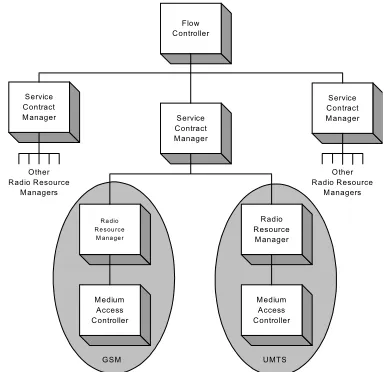
III. DESCRIPTION OF LOGICAL ENTITIES The architecture consists of a collection of RM entities with predefined functionality, as shown in Figure 1. The entities reside in a hierarchy whereby a portion of RM control is devolved to entities at lower levels.
Service Contract Manager
R a dio R e sou rce M ana ge r
Radio Resource Manager
Medium Access Controller Medium
Access Controller
Service Contract Manager Flow
Controller
Service Contract Manager
GSM UMTS
Other Radio Resource
Managers
Other Radio Resource
[image:2.595.328.522.265.451.2]Managers
Figure 1 Proposed RM Architecture
Flow Controller
The Flow Controller (FC) participates in QoS provision on a flow level, it implements a type of admission con-trol similar to Call Admission Concon-trol (CAC) function-ality within an organisation's network. The FC is also in control of routing within the network. This entity reflects the need to keep the architecture as generic as possible and this recognises current research that examines di-viding elements of a multimedia call into separate flows, e.g. a video call could be divided into speech and video flows; MPEG-4 allows this kind of separation [2]. The architecture is flexible enough to allow the operators to support different flows over different access methodolo-gies, e.g. objects in a web page could be simultaneously downloaded in parallel over Wireless LAN and cellular air-interfaces.
per hop behaviour where appropriate), required com-mitment level and direction. An FCon shares many similarities with that of a UMTS Bearer Service which describes the QoS that should be provided to a call be-tween the mobile and the edge of the UMTS network. At call set-up an FCon is sent to the FC describing the application’s QoS requirements. This information is used by the FC to implement a flow level admission control algorithm as follows. An FC has a number of SCMs un-der its supervision; one per cell-site. In case an HCS is implemented, the same geographical area may be served by more than one cell-site and hence SCM. At call set-up based on the parameters specified in the FCon, the FC compiles a Connection Contract (CCon) detailing the QoS requirements of one or more flows pertaining to an admission request across the Radio Access Network only, i.e. between the mobile and the core network. A copy of the CCon is sent by the FC to each of the SCMs under its supervision (serving the location of the user). The FC will receive messages from the SCM it super-vises indicating their ability to support the offered traf-fic. The FC selects the most appropriate group of SCMs since different flows may be supported by different SCMs, taking into account the degree of commitment with which each flow can be supported by the SCMs, the cost for supporting the traffic (including financial, and impact on radio resources), and user's mobility profile. The CCon contains many of the same fields as the FCon, however, there is a significant difference; the parameters specified in the CCon relate only to the bearer between the Core Network and the Mobile Terminal, i.e. these are not end-to-end attributes. The parameters may contain: throughput data, e.g. bit-rate bounds and burstiness, fi-delity (packet loss, Frame Error Rate, BLER, BER), la-tency (delay across the RAN only), jitter, flow treatment (priority, connectionless or connection-oriented, ATM adaption layer, SDU information2), required commitment
level, and direction. Just as the FCon has similarities with the UMTS Bearer Service, the CCon has similari-ties with the UMTS Radio Access Bearer Service. When informed by a SCM that a flow controlled by the FC can no longer be supported under the terms of the contract, the FC can then take the following actions: 1. Determine if another SCM can handle the flow. 2. Determine if QoS re-negotiation is achievable. 3. Drop the flow/call.
Service Contract Manager
The SCM assumes control of all radio resources at a cell-site, where a cell-site is defined as the graphical location of base station equipment of one or more air-interfaces, e.g. GSM and UMTS. Thus the SCM is air-interface independent and is unconcerned with the structure and type of radio bearers - defined by FDMA/TDMA time-slots or CDMA codes. The SCM receives estimates of radio bearer availability and quality from the RRM.
2 In the context of a Connection Contract, SDU information describes
the higher layer packet information: layer 3 & 4 protocol types, e.g. IP, UDP, packet size, need for packet reassembly.
Based on this information the SCM may instruct the RRM to: reserve resources for future calls, allocate bear-ers to traffic, cleardown a specific radio bearer, or han-dover a portion of traffic from one RRM to another at the same cell-site (inter-system handover). The SCM also receives indicators of the status of radio bearers that are currently carrying traffic. The SCM collates this in-formation and computes composite QoS indicators for flows where a single flow is mapped onto many bearers (where appropriate). Thus the SCM views QoS at a higher level than the RRM.
The SCM supervises one or more RRMs. By existing at a level of abstraction above the RRMs the SCM can fa-cilitate inter-system handover, mobility management, and traffic engineering right up to the air-interface. Where RRMs are unable to fulfil the QoS requirements of individual flows the SCM is informed. The SCM can take a range of actions to tackle the situation, including:
• Determine whether another subordinate RRM can handle the flow, e.g. a different RRM represents either a different layer in a HCS or a different air-interface.
• Inform the FC that QoS provision cannot be met. Each SCM keeps an internal database detailing the state of radio resources (for all air-interfaces) under its juris-diction. On receipt of a CCon from the FC, the SCM consults the database and determines whether the QoS requirements can be met given the current state of its radio resources. A CCon accept/reject message is re-turned to the FC with the estimated commitment level. Radio Resource Manager
The RRM is responsible for the control of radio bearers of a specific air-interface at a specific cell-site. The RRM continually monitors the state of radio bearers un-der its jurisdiction - bearer availability & quality esti-mates. The status of the radio bearers is periodically re-ported to the SCM that supervises the RRM. Such radio measurements are required in cellular systems. UMTS specification [3] requires the mobile to be able to meas-ure a range of metrics including: Received Signal Code Power, Carrier Received Signal Strength, and Transport Channel BLER3. The UTRAN is also required to
meas-ure a range of metrics which include: Received total wide band power, Signal to Interference Ratio, Transport Channel BER, and Physical Channel BER.
The RRM is also responsible for managing the state of flows over the radio channels. As the state of the radio channel changes the RRM intervenes to ensure the re-quested QoS requirements are met for these flows. This may include modification of modulation scheme or channel coding (Link Adaptation & AMR), and intra-system Dynamic Channel Allocation (DCA). If the RRM cannot meet these requirements the SCM is informed.
3The terminal is also able to measure BLER- this information is
Medium Access Control
The MAC entity resides at the lowest level in the re-source management hierarchy. It receives instructions from the RRM to allocate and de-allocate traffic to bear-ers, it is the MAC entity that decides which traffic is mapped onto which physical radio bearers. The MAC layer regularly reports the bearers quality to the RRM.
IV. MODIFICATION OF EXISTING SYSTEMS In order to implement the Resource Management Archi-tecture in a UMTS system, for example Release 99, ma-jor modification may not be necessary given the many similarities between the traffic descriptors (Flow & Con-nection Contracts) and the bearer services defined for UMTS. Furthermore many of the UMTS logical entities share similarities with the Resource Management enti-ties. These similarities are discussed in this section.
RRM
MAC
SCM FC
MSC/ SGSN RNC
[image:4.595.96.248.272.355.2]Node B
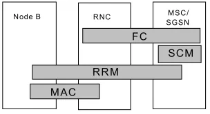
Figure 2 Mapping RM Architecture onto R99 Within the RM Architecture the FC is responsible for admission control and for management of flows once admitted into the system. Within the context of the UMTS Architecture CAC is governed by the RNC since the relative scarcity of radio resource in a particular area determines whether a call will be admitted. It is the (Controlling) RNC that has full knowledge of the state of radio bearers. Once a flow is admitted into the UMTS network it is the responsibility of the (Serving) RNC to manage that flow by the establishment of Radio Access Bearer Services that meet its QoS requirements. The FC is also responsible for routing flows within the mobile network - functionality that resides in the 3GMSC. Hence, as shown in Figure 2, the FC functionality re-sides in the UMTS RNC and MSC.
The SCM is responsible for managing all radio resources of all air-interfaces at a particular geographical location. Since the SCM is air-interface independent it must reside in a location outwith the Radio Access Network - at the edge of the Core Network (MSC/SGSN). The SCM re-ceives a CCon (essentially traffic QoS descriptor for the RAN) from the FC; based on this information it decides which HCS layer or air-interface is most suitable for the service. This involves the creation of bearer services across the RAN. In UMTS Radio Access Bearers are created on request of the MSC – this highlights a simi-larity between the two entities. Furthermore, UMTS specifications permit the MSC to initiate a handover for traffic engineering reasons, like the SCM. Therefore, the SCM functionality would reside within the MSC/SGSN. The RRM controls all the radio resources on a particular air-interface and perhaps on a particular HCS layer. The RRM is aware of the status of ongoing connections over
the air-interface, and of the availability of radio chan-nels. It responds to variations on channel conditions to maintain the QoS required for the flow, this may include link adaptation, power control, etc. In UMTS this func-tionality is devolved to three separate entities; the MSC, RNC, and Node B – therefore a portion of the RRM’s functionality would reside in all three entities.
In the UMTS Architecture the RNC controls and main-tains all radio resources on its associated base stations through Radio Bearer Services [4]. The centralised con-trol of all radio resources from the RNC includes: chan-nel allocation, adaptive multirate coding, and scheduling [5]. In the RM Architecture this functionality resides in the RRM and MAC entities therefore part of theses logi-cal entities reside in the RNC. The base station performs channel coding for example, within the scope of the RM Architecture this functionality resides in the MAC entity. Furthermore the base station is also involved in inner loop power control procedures therefore a portion of the RRM also resides in the base station. The base station contains radio transmission equipment (modulators, channel coding, rate adaption, spreading). Nonetheless some RM resides here; inner loop power control. The MSC is also involved to a limited extent in radio re-source management in that it can instruct the RNC to initiate handover for traffic engineering reasons.
The mapping of the functional entities of the RM Archi-tecture developed within MVCE, onto UMTS network elements is shown in Figure 2. The compatibility of the two architectures is not limited to the roles of the indi-vidual entities. As mentioned, the traffic descriptors (Flow and Connection Contracts) have similarities to the bearer service attributes defined for UMTS.
U M T S B e a r e r S e r v ic e
R a d io A c c e s s B e a r e r S e r v ic e C N B e a r e r
R a d io B e a r e r S e r v ic e
G M S C /G G S N M S C /S G S N
R N C N o d e B
T E T E
E n d - to - E n d S e r v ic e
E x t e r n a l B e a r e r
I u B e a r e r
B a c k b o n e B e a r e r
Figure 3 UMTS Bearer Services
[image:4.595.313.535.472.586.2]C om bine d R N C /BS C
T o C ore N etwork
G S M B S U M T S T D D BS
U M T S F D D BS
[image:5.595.88.251.56.172.2]M ulti a ir-in terface R N S
Figure 4 Ideal Arrangement
A CCon is passed to the SCM where it describes the QoS characteristics required by the flow over the RAN to the edge of the Core Network. As such it is analogous to the attributes that describe the Radio Access Bearer Service. Thus when implemented on the UMTS network, the CCon would simply take the form of a set of Radio Access Bearer Service attributes.
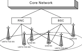
The RM Architecture does not map entirely onto the UMTS Network Architecture Release 99. The differ-ences relate to the separation of radio resource manage-ment functionality into air-interface independent and dependent entities. This requires a single entity (the SCM) to have control over all radio resources in a geo-graphical area, giving rise to the sort of architecture de-picted in Figure 4
Core Network
RNC BSC
G SM BS
G SM BS
G SM BS UMTS FDD BS
UMTS FDD BS
UMTS FDD BS
Figure 5 Release 99 Arrangement
However, Release 99 does not permit the radio technol-ogy to be connected to the network in this aggregated fashion. It is required that disparate radio technologies are operated as isolated units and connected to the CN, as shown in Figure 5. This difference highlights the need for integration of radio technologies at the RNC/BSC level, if the full benefit of the RM Architecture is to be realised (trunking gain, load sharing, etc.). The need for technology integration has fuelled recent research into units acting as joint RNCs/BSCs [6]. This represents a move away from distributed control of several radio ac-cess methodologies towards co-ordinated control from a centralised entity responsible for radio resources in a given area – the approach taken by the RM Architecture. Another area where the UMTS architecture would re-quire alteration is in the provision of commitment. As previously explained, commitment is related to bearer QoS. The real advantage of introducing the concept of commitment is that QoS parameters can be described in a statistical sense, which is particularly beneficial for data services. In fact, the need for a statistical description
of traffic is partially recognised in the UMTS specifica-tion of Radio Access Bearer Service attributes [6, p.22], which contains an attribute to state whether the flow is speech, i.e. conforms to the well known voice activ-ity/DTX model - this may be used to allow more flexible admission control and hence QoS provision. In order to permit the concept of commitment to be introduced to UMTS networks the attribute sets that describe each of the bearer services requires amendment to allow an op-tional commitment level attribute to be introduced.
V. SUMMARY & CONCLUSIONS
This paper has presented a generic RM Architecture that provides a means of co-ordinated radio resource man-agement. It includes an air-interface independent entity, i.e. Service Contract Manager, that controls radio re-sources irrespective of the access methodology, and an entity that exclusively controls resources for a particular access methodology, i.e. Radio Resource Manager. It also recognises the drive towards IP-based networks both in the Core and the RAN – such networks will be required to offer a range of service types. A mechanism for specifying the QoS at different levels in the network is proposed in the form of a commitment level.
By example it has been shown that the architecture is feasible and could be implemented with some modifica-tion in UMTS R99 networks. Potential benefits associ-ated with the concept of commitment level as a UMTS bearer attribute have been highlighted. The need for co-ordinated RM across methodologies is addressed by the SCM. Indeed a similar approach is being examined [6] whereby an additional entity, Common Radio Resource Management Server, exists between the RAN and the CN to facilitate co-ordination. This work will be ex-tended to examine ways in which the RM architecture can serve future mobile systems; UMTS R6 and beyond.
VI. ACKNOWLEDGEMENTS
The work reported in this paper has formed part of the WA2 of the Core II Research Programme of the Virtual Centre of Excellence in Mobile & Personal Communi-cations, Mobile VCE, www.mobilevce.com, whose funding support, including that of EPSRC, is gratefully acknowledged. More detailed technical reports on this research are available to Industrial Members of MVCE.
REFERENCES
[1] 3GPP, 3G TR 25.933 v 1.5.1: IP Transport in UTRAN Work Task Technical Report, December 2001.
[2] ISO/IEC, Information technology -- Coding of audio-visual objects -- Part 1: Systems, ISO/IEC 14496-1, 1999 [3] 3GPP, 3G TS 25.215 v 3.9.0: Physical layer -
measure-ments (FDD), December 2001.
[4] 3GPP, 3G TS 23.107 v 3.3.0: QoS Concept and Archi-tecture, June 2000.
[5] H. Holma and A. Toskala, WCDMA for UMTS: Radio Access for Third Generation Mobile Communications. Wiley, 1st ed., 2000.
[image:5.595.83.257.380.487.2]