Received July 23, 2019, accepted August 2, 2019, date of publication August 6, 2019, date of current version August 21, 2019.
Digital Object Identifier 10.1109/ACCESS.2019.2933470
Artificial Neural Network for LiDAL Systems
AUBIDA A. AL-HAMEED 1, SAFWAN HAFEEDH YOUNUS 1, AHMED TAHA HUSSEIN1,
MOHAMMED THAMER ALRESHEEDI2, AND JAAFAR M. H. ELMIRGHANI 1
1School of Electronic and Electrical Engineering, University of Leeds, Leeds LS2 9JT, U.K. 2Department of Electrical Engineering, King Saud University, Riyadh 11451, Saudi Arabia
Corresponding author: Jaafar M. H. Elmirghani ([email protected])
This work was supported in part by the Engineering and Physical Sciences Research Council (ESPRC) through INTelligent Energy awaRe NETworks (INTERNET) project under Grant EP/H040536/1, SwiTching And tRansmission (STAR) project under Grant EP/K016873/1, and the Terabit Optical Wireless Systems (TOWS) project under Grant EP/S016570/1, and by the Deanship of Scientific Research through the International Scientific Partnership Program ISPP at King Saud University, Saudi Arabia, under Grant ISPP#0093. The work of A. A. Al-Hameed was supported in part by the Higher Committee for Education Development in Iraq (HCED) and in part by the University of Mosul through the Ph.D. Scholarship. The work of S. H. Younus was supported by the Ninevah University through the Ph.D.
Scholarship.
ABSTRACT In this paper, we introduce an intelligent light detection and localization (LiDAL) system
that uses artificial neural networks (ANN). The LiDAL systems of interest are MIMO LiDAL and MISO IMG LiDAL systems. A trained ANN with the LiDAL system of interest is used to distinguish a human (target) from the background obstacles (furniture) in a realistic indoor environment. In the LiDAL systems, the received reflected signals in the time domain have different patterns corresponding to the number of targets and their locations in an indoor environment. The indoor environment with background obstacles (furniture) appears as a set of patterns in the time domain when the transmitted optical signals are reflected from objects in LiDAL systems. Hence, a trained neural network that has the ability to classify and recognize the received signal patterns can distinguish the targets from the background obstacles in a realistic environment, especially given the mobility of targets (humans) which distinguishes them from static obstacles (furniture). The LiDAL systems with ANN are evaluated in a realistic indoor environment through computer simulation.
INDEX TERMS Neural network, ANN, optical indoor localization, VLC systems, people detection,
counting, localization.
I. INTRODUCTION
Visible light communication (VLC) is part of optical wireless communication (OWC) that uses light as a carrier to modu-late the information signal in the visible spectrum (380nm to 780nm) [1]–[4]. VLC systems are becoming more pop-ular everyday due to their inherent advantages over radio frequency (RF) systems. The advantages include a large unregulated spectrum, low complexity of transceiver units, freedom from fading, confidentiality and immunity against interference from electrical devices [5]–[8]. VLC systems can support indoor high data rate communication [6], [8] under-water communication [9], [10], LED to LED communica-tion [1], [11] and indoor user localizacommunica-tion [12], [13]. In [14], a light sensing system using VLC (LiSense) was proposed to track human gestures and reconstruct human skeleton move-ments. The LiSense system makes use of 324 photodetector
The associate editor coordinating the review of this manuscript and approving it for publication was Mostafa Rahimi Azghadi.
array placed on the floor to sense the beacon signals sent from the light sources (VLC transmitters) to recover the human shadow pattern created by individual VLC transmit-ters. A laser radar in conjunction with VLC system was introduced in [15] to provide vehicle to vehicle ranging and VLC communication.
People detection and counting in an indoor environ-ment (such as in offices, exhibition halls and shopping malls) can provide useful information for different applica-tions [16]–[18]. For example, human presence detection is valuable for security purposes. Also knowing the number of people in a supermarket may have an important practical use in terms of marketing, management, optimization and maintaining a high quality of service.
an indoor environment passive infrared (PIR) sensors can be activated wrongly by heat currents from heating and air conditioning [19]–[21]; (ii) the reflected signal from the background is very similar to the one reflected by a person, thus separating a person from the background is an essential requirement for human sensing in a realistic environment. Also, for RADAR and LADAR sensing systems, the reflected received signal suffers from multipath propagation leading to fooling the sensing system and to false person detec-tion (phantom detecdetec-tion) [19]; and (iii) people behaviour is unpredictable with a high degree of similarity such as walking in random paths that may change suddenly result-ing in a serious challenge to localize and track individuals correctly [19].
Ultra-wideband (UWB) RADAR systems with a trans-mitted signal bandwidth greater than 500 MHz have been introduced to detect, localize and track humans in the indoor environment [20], [22], [23]. The UWB carrier signal with a typical frequency range of 3.1 GHz to 5.3 GHz can penetrate walls, furniture and human body [24]. This enables UWB RADAR systems to support various applications such as human movement detection through-walls for security appli-cations and biomedical appliappli-cations (i.e. monitoring human vital signs) [25], [26]. In UWB RADAR, detection of the target (human) depends on the target motion where the human movement causes changes in frequency, phase and time of arrival.However for UWB radar employed in an indoor environment, the effects of signal scattering and absorption by obstacles significantly impair the performance of UWB indoor radar [19], [20].
Binary sensors such as Passive Infrared (PIR) sensors, break beam and binary Doppler sensors have been used to detect human presence and rely on the human motion [19], [27], [28]. The main drawback of binary sensors is their large false detection. For example, the PIR system is temperature dependent, thus any change in the environment tempera-ture leads to a vast number of detection failures. Doppler shift sensors use the concept that signals reflected from a mobile object suffer a frequency shift depending on the object’s speed. The Doppler shift sensor can provide a speed measurement of the detected human unlike the PIR sensor. In [29] a one dimensional Doppler radar was proposed to detect stationary humans relying on the motion of human breathing lungs. A laser radar (LADAR) has been used to detect people based on their shape through extracting high resolution two and/or three dimensional snapshots of the environment [30], [31]. In [32] a single 360-degree LADAR system was introduced to detect and track people in an indoor environment. However, the main disadvantage is the system complexity, eye safety due to the laser beam and the relatively long time needed to scan the environment with high resolu-tion which may lead to miss detecting humans walking at a fast pace.
A light detection and localization (LiDAL) system was proposed in [33] for detection, counting and localization in an indoor setting. The LiDAL system focuses on human
sensing to provide people with spatio-temporal indoor local-ization information. It carries out presence detection, count-ing, localization and tracking. In this application, people can be distinguished from the background due to their dynamic characteristics that arise from their activity (siting/standing) and motion (walking), while stationary people are unde-tectable [33].
In this paper, we expand the work proposed in [33] for peo-ple detection, counting and localization using LiDAL systems namely; MIMO LiDAL and MISO IMG LiDAL systems. We introduce an intelligent LiDAL system that uses artificial neural networks (ANN). Based on our observations in the LiDAL systems introduced in [33], the received reflected signals in the time domain have different patterns correspond-ing to the number of targets and their locations in an indoor environment. The indoor environment with obstacles (furni-ture) appears as a set of patterns in the time domain when the transmitted optical signals are reflected from objects in MIMO LiDAL systems. The patterns appear in the spatial domain in the imaging receiver pixels in MISO IMG LIDAL systems. When targets enter the environment, they add to/ change the temporal and spatial reflection patterns in the room. Therefore, a trained neural network that has the ability to classify and recognize the received signal patterns can distinguish the targets from the background obstacles in a realistic environment.
The main contributions of this paper are as follows: (i) we have introduced for the first time an ANN and used it to learn the radar-like reflections induced by our LiDAL systems and used the ANN for localization and counting of targets; (ii) we used human mobility patterns with the trained ANNs to distinguish humans from sta-tionary obstacles (furniture); (iii) we introduced two main new ANN based systems: MIMO-LiDAL ANN and IMG-LiDAL ANN and compared their performance showing that the IMG-LiDAL ANN outperforms the other systems in this paper and other LiDAL systems (iv) we determined the impact of changes in the environment (furniture locations) on the ANN systems showing their robustness, but also their limits.
This paper is divided into section as follows: Section II considers the design of the MIMO LiDAL and MISO LiDAL systems. Section III introduces the ANN training used in the LiDAL systems. Section IV presents the simulation setup, the target mobility model and realistic indoor environment. Section V presents the results and discussion. Finally, con-clusions are drawn in Section VI.
II. LiDAL SYSTEMS
A. A. Al-Hameedet al.: ANN for LiDAL Systems
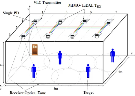
FIGURE 1. MIMO LiDAL System.
A. MIMO LiDAL SYSTEM
The MIMO-LiDAL system is used to detect, count and local-ize targets [33]. The system consists of multiple LiDAL trans-mitters and multiple LiDAL receivers. The MIMO-LiDAL system employs a single photodetector receiver collocated with each VLC transmitter (luminaire, light source) which represents a transceiver unit (TRX). The MIMO-LiDAL sys-tem has eight transceiver units placed in the room ceiling as can be seen in Fig. 1. Each transceiver unit covers a circular optical detection zone with a radius of 1.25m. The transceiver units are spaced by 2m [33]. In the MIMO LiDAL sys-tem considered, the total number of optical detection zones was 8. The MIMO-LiDAL system is designed to resolve the ambiguity of target detection and localization by imple-menting collaboration between the neighbouring transceiver units [33]. The target localization is tackled by joint use of three transceiver units working together through three sys-tem scans (three consecutive listening (frame) times). The MIMO-LiDAL listening time is divide into N time slots where the time slot width is 2ns (equal to the transmitted pulse width) which enables a1R=30 cm target detection resolu-tion for MIMO LiDAL system as reported in [33]. A time of arrival (TOA) technique is used to calculate the target range from a transceiver unit [33]. The target range calculation is based on the trip time of the reflected pulse from the target and the speed of light. The three ranges obtained from the transceiver units are used with a triangulation method to determine the intersection of the (circles) ranges resulting in an estimated target location on the detection floor [33].
B. MISO IMG LiDAL SYSTEM
The MISO IMG LiDAL system is used to detect, count and localize targets. The system employed multiple LiDAL transmitters units with a single imaging receiver. In the MISO IMG LiDAL system, the imaging receiver was placed in the centre of the room’s ceiling as can be seen in Fig. 2 [33]. In MISO IMG LiDAL system design, the imaging receiver has an array of (8 columns×16 rows) pixel receivers [33].
FIGURE 2. MISO IMG LiDAL System.
The MISO IMG LiDAL system forms an image ofNP=128
pixels where every pixel receiver covers a narrow optical detection zone. The benefits of the massive number of pixels are in enabling spatial selection to separate the targets in multiple narrow optical zones. Thus the MISO IMG LiDAL system can: (i) eliminate the ambiguity of target detection and localization and (ii) minimize the interference resulting from the reflections of the background obstacles [33]. In the MISO IMG LiDAL system, the target detection resolution1Swas 0.5m (i.e. the LiDAL system is able to separate two targets at a distance of 0.5m) [33]. The MISO IMG LiDAL system employs a direction of arrival (DOA) method to determine the target location where the image of the target in the pixels that cover the optical zones determines the target location [33]. It is worth mentioning that, the imaging receiver of 128 pixels was divided into 8 groups with 16 pixels per group [33]. Each group of receiver pixels (GRP), works separately with one transmitter during the MISO IMG LiDAL scan (snapshot).
C. BACKGROUND SUBTRACTION METHOD (BSM)
The background subtraction method (BSM) was introduced and examined in [33]–[35]. In this method, the received reflected signals during multiple radar scans are subtracted in order to distinguish the moving target. The BSM relies on the fact that the received signal from the background obstacles (furniture) is stationary (time-invariant) and the received signal reflected from the target is time-variant due to its motion. It is worth mentioning that subtracting two or more received signals leads to enhancing the variance of the white Gaussian noise. Moreover, the performance of BSM is significantly degraded in case the mobile target moves in the horizontal distance where its signal reflections arrive at the same time during radar scans resulting in miss-distinguishing the mobile target [34]–[36].
D. CROSS CORRELATION METHOD (CCM)
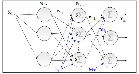
[image:3.576.300.533.66.237.2]FIGURE 3. Block diagram of the LiDAL neural network.
distinguished relative to the stationary background obstacles by correlating the received reflected signals through multi-ple LiDAL snapshot measurements in order to monitor the change due to target mobility. It is worth mentioning that the cross-correlation method has better performance than the Doppler method in terms of detecting the change of targets of interest when the targets move at low speed [37]. Also, the cross-correlation has the benefit of detecting weak received reflected signals and is more robust in the presence of noise [33], [38].
III. NEURAL NETWORK FOR LIDAL SYSTEMS
In this section, we introduce the ANN with the MIMO LiDAL and MISO IMG LiDAL systems. Many algorithms have been employed to train artificial neural networks. The backpropa-gation (BP) algorithm is one of the most popular approaches that have been used to train neural networks due to its effi-ciency and simplicity [39]–[41]. In this paper, a supervized learning algorithm with backpropagation is deployed to train multi-layer neural networks.
In the MIMO LiDAL systems investigated in this paper, we employed an ANN in each light unit (transceiver) and therefore this ANN covers one optical zone. This ANN has to measure one of the three distances needed to localize a target. The other two distance measurements (bistatic or monostatic measurements) are then carried out by uploading different weights in the ANN.
The received reflected signals were sampled at a sampling rate of 1/TsaMIMO, and the samples were grouped intoNslot
time slots. The number of input nodes in the ANN is equal to the total number of samples taken, with each group of samples (ie each group of ANN nodes) labelled as a time slot. The time slot duration is Ts and therefore, the total number of
input nodes in the ANN isNinMIMO=Nslot Ts/TsaMIMO
as can be seen in Fig. 3. The output of the ANN hasNslot nodes,
where the output of each node is a one or zero indicating the presence or absence of a target in that time slot. Hence, the ANN is firstly trained in the given optical zone in the presence of furniture (obstacles) and the absence of targets, resulting in an all zero output. The ANN is then trained in the presence of single or multiple targets, with the supervision indicating the time slot that has a target (one).
FIGURE 4. ANN receiver for MIMO LiDAL system.
For the MISO-IMG-LiDAL system, the number of ANNs used to cover the entire room is equal toLtx, the number of
active transmitters, ie the number of ‘groups of pixels’ (see Fig. 5) [33]. For example, in the room in Fig. 2,Ltx = 8,
thus 8 ANNs are needed in the room. The total number of pixels in the imaging receiver isNP, and therefore the number
of pixels observed by each ANN is NP/Ltx. A snapshot /
image is taken by the imaging receiver everyTsaIMG which is our sampling period here. Note that the input to the ANN should have more than a single time sample per pixel to result in improved robustness against variations in the envi-ronment. In the MIMO LiDAL system,Ts/TsaMIMOsamples
were taken per time slot to help the ANN deal with chan-nel and environment (obstacles) impairments. The imaging receiver pixels see 1S = 0.5m on the room floor, while MIMO LiDAL system has1R = 0.3m on the floor [33]. Therefore, we increased the number of samples taken by the MISO-IMG-LiDAL system by a factor1S/1R. For fairness, we also set the sampling rate in the two systems to the same value,TsaIMG=TsaMIMO. Hence, the number of input nodes in the MISO-IMG-LiDAL ANN,NinIMG, is
NinIMG = Ts
TMIMO sa
1S
1R
NP
Ltx
(1)
The MISO-IMG-LiDAL ANN hasNP/Ltx outputs where
each output represents a pixel and indicates in a binary fash-ion the presence or absence of a target in the FOV of that pixel. Next we will introduce the methods used in training the ANNs.
A. THE NEURAL NETWORK TRAINING PROCESS
[image:4.576.42.272.66.188.2]A. A. Al-Hameedet al.: ANN for LiDAL Systems
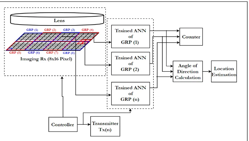
FIGURE 5. ANN receiver for MISO IMG LiDAL system.
a neural network with a few hidden neurons may have a lim-ited learning memory with inadequate performance (under-fitting) [42]. In this paper, we considered a pruning approach in order to optimize the number of hidden neurons (Nm) [43]. The number of hidden neurons is calculated as [44]:
Nm=
(Nin+Y)
βi
(2)
where Y is the number of output neurons (Y =
NP/Ltx or Y = Nslot for the MISO-IMG-LiDAL and
MIMO-LiDAL systems respectively), Nin is the number of
the input neurons (given byNinIMG orNinMIMOfor the MISO-IMG-LiDAL and MIMO-LiDAL systems respectively) and
βis an arbitrary pruning factor (hereβ ∈[1,2. . .Nin] [44]).
The training process uses the following steps:
i. Provide inputs to the neural network made up of the input samplesXi, the initial number of hidden neurons
Nmfor a givenβi, the initial weights (wij), connecting
the input layer and the hidden layer, the initial weights (wjk) connecting the hidden layer and the output layer;
and provide the initial biasing input weightsLjandMk.
ii. Calculate the outputs of the hidden neurons associated with the inputsXi,weightswijand biasing weights (Mk)
and apply the result as an input to the neuron activation function resulting in [45], [46]:
Nj=S Nm
X
i=1
wijxi+Lj
!
j∈[1, . . .Nm],
i∈[1, . . .Nin] (3)
whereSis the node activation function, and a sigmoidal function was used,S(t)= 1
1+e−t.
iii. Calculate the predicted output value (Yk) depending
on the outputs of the hidden neurons (Nmj) and their
weightswjk with basing weights (Mk), where the
out-putYk can be written as [46]:
Yk = m
X
j=1
Njwjk +Mk k∈[1, . . .Y] (4)
iv. Calculate the error associated with the predicted (yk)
considering the actual number of targets (ANk).
e=
Y
X
k=1
Ak−yk (5)
v. Optimize the weights and biasing. In our approach, we used the Levenberg-Marquardt algorithm (LMA) which is known to be a stable, fast and efficient algo-rithm with slow error convergence 45], [47]. According to LMA all the network connection weights and biasing weights are updated as defined in [48], [49]:
wn+1=wn−
h
JnTJn+µr I
i−1
Jnen (6)
whereµris the learning coefficient,Iis identity matrix and J is the Jacobian matrix which is calculated as in [48], [49].
significant. We tested a different number of hidden neurons using the pruning approach to find the optimal number of hidden neurons Nm which was 15 and 27 for the
MIMO-LiDAL and MISO-IMG-MIMO-LiDAL systems respectively. The mean square error in the training phase was about 10−5 validated through 20% of the snapshots.
During the system set-up, the neural network can be trained in situ in the scene, i.e. in the environment where it is to be used. Neural network retraining for any indoor environment can be done through scanning the pulse reflection patterns in the environment in the absence of any targets to determine the obstacles’ (furniture) reflection patterns. Targets are then inserted in the environment and the new reflection patterns in the presence of the targets are determined, thus training the ANN.
Fig. 4 presents the proposed block diagram of the ANN receiver for MIMO LiDAL systems. The controller conducts the targets detection and localization process as follows:
1) The control signal activates the transceiver unit of LiDAL to (i) transmit an optical pulse signal from the transmitterTx(n), and (ii) activates the receiverRx(n) to collect the reflected signal.
2) The receiver Rx(n)listens to the reflected signal in an observation widow of durationT. A trained ANN is activated to process the received signal to detect the targets’ presence and their ranges and update the counter as can be seen in Fig. 4.
3) For target localization, the controller finds theN neigh-bouring LiDAL transmitters. We considered N = 2 [33], the neighbouring transmitters areTx(n+1), and Tx(n+2) as can be seen in Fig. 4 in conjunction with the receiverRx(n). The three trip times (one fromTx(n), and two from neighbouringTx(n+1), andTx(n+2)) are then used to determine the targets’ locations using TOA.
4) Target elimination follows where the targets located in the overlap zones are counted only once in the MIMO LiDAL system (see Fig. 1). Due to position errors, duplicate targets are eliminated then the counter is updated accordingly.
Fig. 5 shows the proposed schematic ANN receiver dia-gram for MISO IMG LiDAL systems. The controller coordi-nates the targets detection and localization process as follows:
1) The controller activates a transmitterTx(n) which sends
an optical pulse, and also activates the group receiver’s pixelsGRP(n) to collect the reflected signals.
2) The controller then updates the value ofn, and ifLtx>
nstep (1) is repeated, whereLtxis the number of active
transmitter units (Ltx =8) of the MISO-IMG-LIDAL
system [33].
3) A trained ANN is used to process the received reflected signals from each group of receiver pixels to detect and count the targets.
4) Finally, pixel identification is employed to estimate the target location by using DOA method.
IV. SIMULATION SETUP AND RESULTS
In this section, we evaluate the performance of the ANN LiDAL systems. In [33] we considered four scenarios: (i) a baseline scenario which represents an empty room that has no furniture and with fully mobile users, ie targets. This is the least demanding environment / scenario; (ii) a challenging localization environment / scenario where there are obstacles in the form of furniture, but the users are fully mobile; (iii) a harsh localization environment scenario where obstacles in the form of furniture are present and in addition the users are nomadic, ie not fully mobile. Here the users move and then stay stationary at points of interests (for example desk areas) before becoming mobile again. This is the most challenging environment or scenario as it is hard to distinguish users or people from furniture; (iv) a case study, which represents a scenario made up of a room where people arrive and depart. In this paper we selected scenario (iii) from [33] as it is the most challenging scenario to compare the different LiDAL distinguishing, localisation and counting methods versus our ANN methods. The four scenarios are compared in [33]. We have avoided reproducing scenarios (i), (ii) and (iv) as these are less demanding scenarios and so as to avoid repetition.
We start by assessing the performance of ANN, BSM and CCM in terms of target distinguishing when the environment changes, ie when the locations of furniture change and con-sider a single target in this case. We then proceed to report results for the ANN-MIMO-LiDAL and ANN-MISO-IMG-LiDAL systems with multiple targets and compare these results to the results reported in [33].
For target mobility, we have considered the directed ran-dom walk with obstacle avoiding which was proposed in [33]. In this model, the target walks freely inside the realistic environment in all directions except directions that lead to background obstacles such as furniture [33].
We have considered a realistic office environment which was reported in [33]. The environment consists of a furnished room, with dimensions of 4 m (width)× 8 m (length) × 3 m (height). The reflection factors for the walls and ceil-ing were 0.8 and 0.3 respectively. The furniture consists of four office desks (1.54 m (width) ×0.76 m (length) × 0.75 m (height)) and one bookshelf (3 m × 0.8 m × 2 m) [33]. The office desks and bookshelf materials were finished-wood with a reflectivity factor of 0.55 and diffuse reflections [26].
The average target of interest (human) dimensions 15 cm×48 cm×170 cm (depth×width×height) were con-sidered [33]. The target reflection was concon-sidered a Gaussian random variable with a mean of 0.72 and a standard deviation of 0.3 [33].
A. A. Al-Hameedet al.: ANN for LiDAL Systems
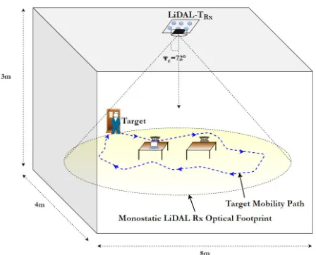
FIGURE 6. Simulation room setup with monostatic LiDAL.
The pedestrian movement speed affects the performance of the LiDAL methods. Higher pedestrian mobility leads to improved performance, especially in terms of target dis-tinguishing as studied on [33]. In particular, the nomadic user in [33], which is the scenario studied in this paper, has the worst performance in terms of target distinguishing. Our ANN methods have however produced a relatively low distinguishing error of 8% in this case as Fig. 7 shows. In the BSM there is high sensitivity to the learning rate due to the added noise that results from the subtraction process. The learning rate µr was set 0.05 which results in slower convergence, but also lower final error where the mean square error was 10−5. The value of the learning rate was set through experimentation using 20% of the development data set.
A. SINGLE TARGET DISTINGUISHING
We have evaluated the performance of the trained neural network when it distinguishes a single target in a realistic environment, as shown in Fig. 6. The evaluation is conducted in two scenarios, the first scenario included a static realistic environment where the background obstacles (furniture) are fixed over the simulation time with a single nomadic target that moves at a speed of 0.5m/s. The second scenario consid-ered a dynamic realistic environment where the positions of some of the background obstacles (furniture) change over the simulation time in the presence of a nomadic target. A mono-static LiDAL system (collocated transmitter and receiver) was used in the room setup as shown in Fig. 6. In addition, we have considered the pathway model proposed in [33] for target mobility with eight interesting locations (LD = 8) in
the room in Fig. 45. Five snapshot measurements per second were collected to capture the target movement during the 5 minutes simulation time. The total number of recorded snapshot measurements was 1500.
MAPE was evaluated for the scenario described above and shown in Fig. 6, where the number of targets is one, however, a large number of snapshot measurements were
FIGURE 7. BSM, CCM and ANN target distinguishing error.
taken as above, while the target moves. The ANN reports target results for each snapshot. The BSM and CCM used two consecutive snapshots. Fig. 7 presents MAPE results, referred to here as the average (over the 1500 snapshot exper-iment) false distinguishing error for the first scenario, ie the static environment. The ANN was pre-trained and optimized for the room shown in Fig. 6. As can be noted in Fig. 7, the ANN has better performance with 8% error compared to CCM and BSM which have 11% and 19% error respectively. Note that for BSM and CCM, LiDAL systems, an optimum detection threshold was derived in [33] taking into account the randomness due to the user clothing and cloth texture, ie reflection coefficient, the randomness due to the user vari-able cross-section at different orientations, the user location and the noise in the environment due to background induced shot noise attributed to lighting and the receiver noise. The optimum threshold was derived in [33]. Also note that in this experiment, there is a single moving target, the furniture is stationary and the percentage error reflects the ability of the methods to distinguish a moving target from furniture over the large number of snapshots considered.
The BSM has the worst performance due to the impact of target presence and movement on the reflections from the background furniture and the particular sensitivity of subtraction to such changes. The ANN and CCM perform better, however, this method fails to distinguish the target only when target-furniture ambiguity occurs. In other words, when the distance between the target and furniture is less than the LiDAL resolution of 0.3m and at the same time, the target remains stationary, (nomadic), for more than 5 snapshots in our experiment. The CCM performance can be improved if the number of processed snapshots is increased to accommo-date target mobility behaviour, however, this may slow the target detection process in LiDAL systems.
[image:7.576.45.269.63.244.2]FIGURE 8. False target distinguishing error in a dynamic environment.
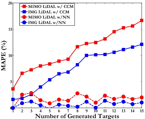
FIGURE 9. Counting MAPE of LiDAL systems using a trained neural network in a realistic environment.
environment, ie change in furniture configurations as can be seen in Fig. 6 where the furniture positons were changed in each simulation. Note that, the ANN was calibrated and optimized before and after the target presence, but the furni-ture locations remained fixed throughout the training phase. As can be noted in Fig. 8, the ANN has the best performance up to 40% change in the locations of furniture (tables in this case). If the furniture locations change by a larger percentage, the CCM performs better. This is attributed to the fact that a change in the furniture locations affects the CCM once only, ie when it happens. Beyond that point, the furniture remains static in its new position and the CCM is thus able to track the moving target. The ANN fails as the environment is now significantly different to that over which it was trained. The sensitivity of the BSM is high throughout as explained earlier. The ANN has an error of 35% with 100% change in the environment. This 100% change in our case means that the
TABLE 1.Simulation parameters.
two tables move from their initial positions at the centre of the room where they are each separated by 0.5m from the centre point of the room, to new locations next to the walls, a 2m movement for the 1.5m×0.9m table. The BSM and CCM performed better than the ANN at 100% change in the environment, with a maximum error of 27% and 13% for BSM and CCM respectively.
B. LiDAL SYSTEMS WITH ANN
[image:8.576.41.273.289.479.2]A. A. Al-Hameedet al.: ANN for LiDAL Systems
TABLE 2. Simulation flow and data collections for ANN training.
simulate and collect data (snapshot measurements) for the neural network training for both MIMO-LiDAL and MISO-IMG LiDAL systems. We set the number of iterations to Itr =250 with 10 snapshots per iteration withimax =15.
Following Table 2, the LiDAL simulation starts by select-ing a given number of targets, initially one target, increasselect-ing to K targets in the room. For the given number of targets selected, each iteration then selects a random reflection coef-ficient for each target (colour and texture of cloths for the target [33]), a random location for the target and random noise are generated at the target location. This is followed by applying the mobility pattern selected for the target using the mobility models in [33]. A number of snapshots are captured at each iteration, 10 snapshots in this paper. Finally, the LiDAL detection algorithm is applied. In this case MIMO-LiDAL ANN or IMG-MIMO-LiDAL ANN. The iterations are then incremented up to the maximum number of iterations of interest; to consider and average over a large number of realizations (250 iterations or realizations were considered in this paper). The number of targets is then increased by one and the entire process is repeated as shown in Table 2 until the maximum number of targets is reached, which is 15 targets / humans, in this paper in the 8 m × 4 m × 3 m room considered. The MAPE and DRMSE are then calculated.
The performance evaluation thus used 250 iterations per target, 10 snap shots per iteration and 15 targets in the study, ie a data set made up of 37,500 snap shots (equivalent to images) of the room were used for the evaluation. The train-ing data set had 10,000 snapshots and while developtrain-ing the algorithms, a data set of similar size was used to select and tune the ANN parameters.
[image:9.576.45.268.84.255.2]Fig. 9. shows the counting MAPE results for LiDAL sys-tems that include and exclude ANNs. The LiDAL syssys-tems that do not employ ANNs, use CCM, the better of the two distinguishing methods. It can clearly be seen in Fig. 9 that the counting MAPE of ANN MIMO-LiDAL is 2% which is significantly lower than the corresponding value, 16%,
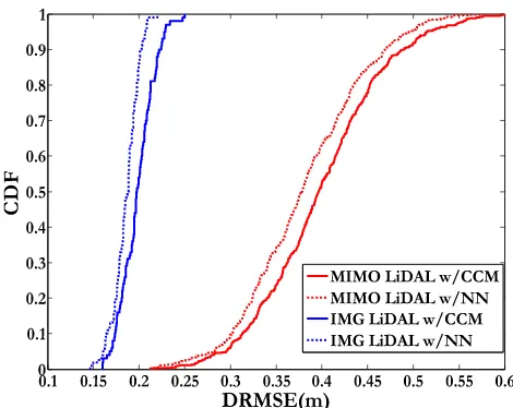
FIGURE 10. CDF of DRMSE of the MIMO LiDAL and IMG LiDAL systems with CCM and ANN.
for MIMO-LiDAL with CCM and the sub-optimum receiver reported in [33]. Furthermore, the performance of MISO IMG-LiDAL with ANN improves, with a maximum counting error of 1%.
Fig. 10 shows the cumulative distribution function of the DRMSE positioning error for the MIMO-LiDAL system and MISO IMG LiDAL with ANN and CCM. As can be noted, the 95% CDF confidence interval is at 0.5m and 0.42m positioning error for MIMO-LiDAL system with CCM and ANN respectively, while the average DRMSE is 0.37m and 0.4m respectively.
It should be observed that overall, the DRMSE values in MISO-IMG-LIDAL are smaller than the corresponding values in MIMO-LiDAL. In the MISO-IMG-LiDAL system, at the 95% confidence interval, Fig. 10, the DRMSE are 0.23m and 0.2m for MISO-IMG-LIDAL with CCM and ANN respectively, whereas the average values of DRMSE are 0.2m and 0.18m for CCM and ANN respectively.
Similarly, Fig. 10 shows that at the 95% confidence inter-val, DRMSE is reduced through the use of ANN from 0.5m to 0.42m for the MIMO-LiDAL system; and from 0.23m to 0.2m in the IMG-LiDAL system. The DRMSE is thus also reduced.
Our ANNs with one hidden layer have produced signifi-cant performance improvements as shown above. It should be noted that the introduction of deep neural networks in conjunction with LiDAL is of great interest. The addition of further hidden layers can enable such ANNs to learn the mobility pattern of users better and hence potentially reduce the distinguishing error below the current value of 8% (note that it is 16% for the non-ANN methods). Care has to be taken however in such cases where deep neural networks are used so as not to ‘over-learn’ the room configuration and human mobility patters presented by the training data.
We have added the following clarification in page 7: It should be noted that we have used the ANNs in this paper as classifiers as they are among the most versatile classifiers. Future work should consider the use of other classifiers including for example support vector machines (SVMs), logistic regression, decision trees and k-nearest neighbors and deep neural networks. An extensive compar-ison between these classifiers in different problems can be found here [50]–[52].
V. CONCLUSIONS
This paper presented new localization systems that employ artificial neural networks with MIMO LiDAL and MISO IMG LiDAL systems for people detection, counting and localization. The results of intelligent LiDAL systems with the trained neural network show that significant improve-ment in the counting and localization are achieved compared with traditional LiDAL systems with distinguishing methods namely; BSM and CCM.
The best performance for our LiDAL systems was obtained when an ANN with forward backward propagation was used for target detection. The MIMO-LiDAL system with ANN in scenario 2 reduced the counting MAPE to 2% from the 16% associated with the MIMO-LiDAL system. In the MISO-IMG-LiDAL system the use of the ANN reduced the count-ing MAPE from 12% to approximately 1%. Furthermore, we studied the impact of training the ANN on a given room, and subsequently changing the furniture locations in the room. In a monostatic configuration with a single target, the counting MAPE was below 11% for up to 40% change in the room furniture locations showing high ANN robust-ness. For furniture location changes beyond 40%, the CCM performs better than ANN as it is able to adapt to the new furniture locations, unlike the ANN which is pre-trained. It is highly likely though that typical changes in room furniture locations will be below 40%, and if above this level, the ANN can include new self-training routines.
ACKNOWLEDGEMENTS
All data are provided in full in the results section of this paper.
REFERENCES
[1] S. Schmid, G. Corbellini, S. Mangold, and T. R. Gross, ‘‘LED-to-LED visible light communication networks,’’ inProc. 14th ACM Int. Symp. Mobile Ad Hoc Netw. Comput., 2013, pp. 1–10.
[2] L. Grobe, A. Paraskevopoulos, J. Hilt, D. Schulz, F. Lassak, F. Hartlieb, C. Kottke, V. Jungnickel, and K.-D. Langer, ‘‘High-speed visible light com-munication systems,’’IEEE Commun. Mag., vol. 51, no. 11, pp. 60–66, Dec. 2013.
[3] S. Arnon,Visible Light Communication. Cambridge, U.K.: Cambridge Univ. Press, 2015.
[4] M. Nakajima and S. Haruyama, ‘‘New indoor navigation system for visu-ally impaired people using visible light communication,’’EURASIP J. Wireless Commun. Netw., vol. 2013, no. 1, p. 37, Dec. 2013.
[5] J. Luo, L. Fan, and H. Li, ‘‘Indoor positioning systems based on visible light communication: State of the art,’’IEEE Commun. Surveys Tuts., vol. 19, no. 4, pp. 2871–2893, 4th Quart., 2017.
[6] D. Karunatilaka, F. Zafar, V. Kalavally, and R. Parthiban, ‘‘LED based indoor visible light communications: State of the art,’’IEEE Commun. Surveys Tuts., vol. 17, no. 3, pp. 1649–1678, Aug. 2015.
[7] T.-H. Do and M. Yoo, ‘‘An in-depth survey of visible light communication based positioning systems,’’Sensors, vol. 16, no. 5, p. 678, 2016. [8] H. Haas, L. Yin, Y. Wang, and C. Chen, ‘‘What is LiFi?’’J. Lightw.
Technol., vol. 34, no. 6, pp. 1533–1544, Mar. 15, 2016.
[9] H. Burchardt, N. Serafimovski, D. Tsonev, S. Videv, and H. Haas, ‘‘VLC: Beyond point-to-point communication,’’IEEE Commun. Mag., vol. 52, no. 7, pp. 98–105, Jul. 2014.
[10] C. Wang, H. Y. Yu, and Y. J. Zhu, ‘‘A long distance underwater visible light communication system with single photon avalanche diode,’’IEEE Photon. J., vol. 8, no. 5, pp. 1–11, Oct. 2016.
[11] S. Schmid, G. Corbellini, S. Mangold, and T. R. Gross, ‘‘An LED-to-LED Visible Light Communication system with software-based synchroniza-tion,’’ inProc. IEEE Globecom Workshops, Dec. 2012, pp. 1264–1268. [12] Z. Zhou, M. Kavehrad, and P. Deng, ‘‘Indoor positioning algorithm using
light-emitting diode visible light communications,’’Opt. Eng., vol. 51, no. 8, 2012, Art. no. 085009.
[13] W. Zhang, M. I. S. Chowdhury, and M. Kavehrad, ‘‘Asynchronous indoor positioning system based on visible light communications,’’Opt. Eng., vol. 53, Apr. 2014, Art. no. 045105.
[14] T. Li, C. An, Z. Tian, A. T. Campbell, and X. Zhou, ‘‘Human sensing using visible light communication,’’ inProc. 21st Annu. Int. Conf. Mobile Comput. Netw., 2015, pp. 331–344.
[15] A. J. Suzuki and K. Mizui, ‘‘Laser radar and visible light in a bidirectional V2V communication and ranging system,’’ inProc. IEEE Int. Conf. Veh. Electron. Saf. (ICVES), Nov. 2015, pp. 19–24.
[16] J. Luo, J. Wang, and H. Xu, ‘‘Real-time people counting for indoor scenes,’’
Signal Process., vol. 124, pp. 27–35, Jul. 2016.
[17] S. Khan, G. Vizzari, S. Bandini, and S. Basalamah, ‘‘Detecting dominant motion flows and people counting in high density crowds,’’ inProc. 22nd Int. Conf. Central Eur. Comput. Graph., Vis. Comput. Vis., 2014, pp. 1–20. [18] J. Luo, J. Wang, H. Xu, and H. Lu, ‘‘A real-time people counting approach in indoor environment,’’ inProc. Int. Conf. Multimedia Mod-eling, in Lecture Notes in Computer Science, vol. 8935, Springer, 2015, pp. 214–223. doi:10.1007/978-3-319-14445-0_19.
[19] T. Teixeira, G. Dublon, and A. Savvides, ‘‘A survey of human-sensing: Methods for detecting presence, count, location, track, and identity,’’ACM Comput. Surv., vol. 5, no. 1, pp. 59–69, 2010.
[20] S. Chang, R. Sharan, M. Wolf, N. Mitsumoto, and J. W. Burdick, ‘‘UWB radar-based human target tracking,’’ inProc. IEEE Radar Conf., May 2009, pp. 1–6.
[21] J. A. Nanzer and R. L. Rogers, ‘‘Human presence detection using millimeter-wave radiometry,’’IEEE Trans. Microw. Theory Techn., vol. 55, no. 12, pp. 2727–2733, Dec. 2007.
[22] F. Liang, F. Qi, Q. An, H. Lv, F. Chen, Z. Li, and J. Wang, ‘‘Detection of multiple stationary humans using UWB MIMO radar,’’Sensors, vol. 16, no. 11, p. 1922, 2016.
[23] A. G. Yarovoy, L. P. Ligthart, J. Matuzas, and B. Levitas, ‘‘UWB radar for human being detection,’’IEEE Aerosp. Electron. Syst. Mag., vol. 21, no. 3, pp. 10–14, Mar. 2006.
[24] S. Singh, Q. Liang, D. Chen, and L. Sheng, ‘‘Sense through wall human detection using UWB radar,’’ EURASIP J. Wireless Commun. Netw., vol. 2011, no. 1, p. 20, Jun. 2011.
A. A. Al-Hameedet al.: ANN for LiDAL Systems
[26] C. G. Bilich, ‘‘Bio-medical sensing using ultra wideband communications and radar technology: A feasibility study,’’ inProc. Pervasive Health Conf. Workshops, Nov. 2006, pp. 1–9.
[27] Q. Hao, F. Hu, and J. Lu, ‘‘Distributed multiple human tracking with wireless binary pyroelectric infrared (PIR) sensor networks,’’ inProc. IEEE SENSORS, Nov. 2010, pp. 946–950.
[28] J. Singh, U. Madhow, R. Kumar, S. Suri, and R. Cagley, ‘‘Tracking multiple targets using binary proximity sensors,’’ inProc. 6th Int. Conf. Inf. Process. Sensor Netw., 2007, pp. 529–538.
[29] S. Z. Gürbüz, W. L. Melvin, and D. B. Williams, ‘‘Detection and identifi-cation of human targets in radar data,’’Proc. SPIE, vol. 6567, May 2007, Art. no. 65670I.
[30] L. E. Navarro-Serment, C. Mertz, N. Vandapel, and M. Hebert, ‘‘LADAR-based pedestrian detection and tracking,’’ inProc. 1st IEEE Workshop Hum. Detection Mobile Platforms, Pasadena, CA, USA, May 2008. [Online]. Available: https://www.ri.cmu.edu/pub_files/pub4/navarro_ serment_luis_ernesto_2008_1/navarro_serment_luis_ernesto_2008_1.pdf [31] T. Taipalus and J. Ahtiainen, ‘‘Human detection and tracking with knee-high mobile 2D LIDAR,’’ inProc. IEEE Int. Conf. Robot. Biomimetics, Dec. 2011, pp. 1672–1677.
[32] J. Shackleton, B. VanVoorst, and J. Hesch, ‘‘Tracking people with a 360-degree lidar,’’ inProc. 7th IEEE Int. Conf. Adv. Video Signal Based Surveill., Aug. 2010, pp. 420–426.
[33] A. A. Al-Hameed, S. H. Younus, A. T. Hussein, M. T. Alresheedi, and J. M. H. Elmirghani, ‘‘LiDAL: Light detection and localization,’’IEEE Access, vol. 7, pp. 85645–85687, 2019. doi: 10.1109/ACCESS.2019. 2925076.
[34] R. Zetik, S. Crabbe, J. Krajnak, P. Peyerl, J. Sachs, and R. Thomä, ‘‘Detection and localization of persons behind obstacles using M-sequence through-the-wall radar,’’Proc. SPIE, vol. 6201, May 2006, Art. no. 62010I. [35] M. Piccardi, ‘‘Background subtraction techniques: A review,’’ inProc.
IEEE Int. Conf. Syst., Man Cybern., vol. 4, Oct. 2004, pp. 3099–3104. [36] A. McIvor, Q. Zang, and R. Klette, ‘‘The background subtraction
prob-lem for video surveillance systems,’’ inProc. Int. Workshop Robot Vis.
Springer, 2001, pp. 176–183.
[37] A. P. Hoeks, T. G. Arts, P. J. Brands, and R. S. Reneman, ‘‘Comparison of the performance of the RF cross correlation and Doppler autocorrelation technique to estimate the mean velocity of simulated ultrasound signals,’’
Ultrasound Med. Biol., vol. 19, no. 9, pp. 727–740, 1993.
[38] Y. W. Lee, T. Cheatham, and J. B. Wiesner, ‘‘The application of correlation functions in the detection of small signals in noise,’’ Res. Lab. Electron., Massachusetts Inst. Technol., Cambridge, MA, USA, Tech. Rep. 141, 1949.
[39] R. Hecht-Nielsen, ‘‘Theory of the backpropagation neural network,’’ in
Neural Networks for Perception. Amsterdam, The Netherlands: Elsevier, 1992, pp. 65–93.
[40] V. V. Phansalkar and P. S. Sastry, ‘‘Analysis of the back-propagation algorithm with momentum,’’IEEE Trans. Neural Netw., vol. 5, no. 3, pp. 505–506, May 1994.
[41] B. M. Wilamowski, ‘‘Neural network architectures and learning algo-rithms,’’IEEE Ind. Electron. Mag., vol. 3, no. 4, pp. 56–63, Dec. 2009. [42] M. T. Hagan, H. B. Demuth, M. H. Beale, and O. De Jesús,Neural Network
Design. Boston, MA, USA: PWS Publishing, 1996.
[43] T. Rajkumar, C. Aragon, J. Bardina, and R. Britten, ‘‘Prediction of aerody-namic coefficients for wind tunnel data using a genetic algorithm optimised neural network,’’WIT Trans. Inf. Commun. Technol., vol. 28, pp. 1–15, Sep. 2002.
[44] J. Heaton,Introduction to Neural Networks With Java. Chesterfield, MO, USA: Heaton Research, 2005.
[45] H. Yu and B. Wilamowski,Levenberg–Marquardt Training, Industrial Electronics Handbook—Intelligent, Systems, vol. 5. Boca Raton, FL, USA: CRC Press, 2011.
[46] F. Hu, L. Wang, S. Wang, X. Liu, and G. He, ‘‘A human body posture recognition algorithm based on BP neural network for wireless body area networks,’’China Commun., vol. 13, no. 8, pp. 198–208, 2016. [47] D. W. Marquardt, ‘‘An algorithm for least-squares estimation of nonlinear
parameters,’’J. Soc. Ind. Appl. Math., vol. 11, no. 2, pp. 431–441, 1963. [48] H. Yu and B. M. Wilamowski, ‘‘Levenberg–marquardt training,’’ in
Indus-trial Electronics Handbook-Intelligent Systems, vol. 5. Boca Raton, FL, USA: CRC Press, 2011, pp. 12-1–12-15.
[49] B. M. Wilamowski, N. J. Cotton, O. Kaynak, and G. Dundar, ‘‘Comput-ing gradient vector and jacobian matrix in arbitrarily connected neural networks,’’IEEE Trans. Ind. Electron., vol. 55, no. 10, pp. 3784–3790, Oct. 2008.
[50] C.-W. Hsu and C.-J. Lin, ‘‘A comparison of methods for multiclass support vector machines,’’IEEE Trans. Neural Netw., vol. 13, no. 2, pp. 415–425, Mar. 2002.
[51] J. Maroco, D. Silva, A. Rodrigues, M. Guerreiro, I. Santana, and A. de Mendonça, ‘‘Data mining methods in the prediction of dementia: A real-data comparison of the accuracy, sensitivity and specificity of linear discriminant analysis, logistic regression, neural networks, support vector machines, classification trees and random forests,’’BMC Res. Notes, vol. 4, no. 1, 2011, Art. no. 299.
[52] T. Liu, A. Abd-Elrahman, J. Morton, and V. L. Wilhelm, ‘‘Comparing fully convolutional networks, random forest, support vector machine, and patch-based deep convolutional neural networks for object-based wetland mapping using images from small unmanned aircraft system,’’ GISci. Remote Sens., vol. 55, no. 2, pp. 243–264, 2018.
AUBIDA A. AL-HAMEED received the B.Sc. degree in electronic and electrical engineering and the M.Sc. degree in communication systems from the University of Mosul, Iraq, in 2010 and 2013, respectively. He is currently pursuing the Ph.D. degree with the school of Electronic and Elec-trical Engineering, University of Leeds, Leeds, U.K. He is also a Higher Committee for Education Developments in Iraq (HCED) Scholar.
SAFWAN HAFEEDH YOUNUS received the B.Sc. degree in electronic and electrical engineer-ing and the M.Sc. degree (Hons.) in communica-tion systems from the University of Mosul, Iraq, in 2008 and 2010, respectively. He is currently pursuing the Ph.D. degree with the School of Elec-tronic and Electrical Engineering, University of Leeds, Leeds, U.K. He was a Maintenance and Support Engineer of the NGN Local Network with the Ministry of Communication, Iraq, from 2010 to 2012. He was a Lecturer with the Communication Department, College of Electronics, University of Mosul, from 2012 to 2014. He is also a Ministry of Higher Education and Scientific Research (MOHESR) of Iraq Scholar. His research interests include performance enhancement techniques for visible light communication systems, visible light communication system design, and indoor visible light communication networking.
MOHAMMED THAMER ALRESHEEDreceived the B.Sc. degree (Hons.) in electrical engineering from King Saud University, Riyadh, Saudi Arabia, in 2006, and the M.Sc. degree (Hons.) in com-munication engineering and the Ph.D. degree in electronic and electrical engineering from Leeds University, Leeds, U.K., in 2009 and 2014, respec-tively. He is currently an Assistant Professor with the Department of Electrical Engineering, King Saud University. His research interests include adaptive techniques for optical wireless (OW), OW systems design, indoor OW networking, and visible light communications.
JAAFAR M. H. ELMIRGHANIreceived the Ph.D. degree in the synchronization of optical systems and optical receiver design from the University of Huddersfield, U.K., in 1994, and the D.Sc. degree in communication systems and networks from the University of Leeds, U.K., in 2014. He joined Leeds University, in 2007. Prior to that, he was the Chair in optical communications with the Uni-versity of Wales, Swansea, from 2000 to 2007. He has founded, developed, and directed the Institute of Advanced Telecommunications and the Technium Digital (TD), a tech-nology incubator/spin-off hub. He is currently the Director of the School of Electronic and Electrical Engineering, Institute of Communication and Power Networks, University of Leeds. He has provided outstanding lead-ership in a number of large research projects at the IAT and TD. He has coauthoredPhotonic Switching Technology: Systems and Networks(Wiley) and has published over 500 papers. His research interests include optical systems and networks. He is also a Fellow of the IET and the Institute of Physics. He received the IEEE Communications Society Hal Sobol Award, the IEEE Comsoc Chapter Achievement Award for excellence in chapter activities, in 2005, the University of Wales Swansea Outstanding Research Achievement Award, in 2006, the IEEE Communications Society Signal Processing and Communication Electronics Outstanding Service Award, in 2009, the Best Paper Award at the IEEE ICC’2013, the 2015 IEEE Comsoc Transmission Access and the Optical Systems Outstanding Service Award in
recognition of the Leadership and Contributions to the Area of Green Communications, the GreenTouch 1000x Award, in 2015, for pioneering research contributions to the field of energy efficiency in telecommunica-tions, the 2016 IET Optoelectronics Premium Award, and shared with six GreenTouch innovators the 2016 Edison Award in the Collective Disruption Category for their work on the GreenMeter, an international competition, clear evidence of his seminal contributions to Green Communications, which have a lasting impact on the environment (green) and society. He has been awarded in excess of the £30 million in grants to date from EPSRC, the EU, and industry and has held prestigious fellowships funded by the Royal Society and BT. He was the Co-Chair of the GreenTouch Wired, Core and Access Networks Working Group, an Adviser to the Commonwealth Scholarship Commission, and a member of the Royal Society International Joint Projects Panel and the Engineering and Physical Sciences Research Council (EPSRC) College. He was the Founding Chair of the Advanced Signal Processing for Communication Symposium, which started at the IEEE GLOBECOM’99 and has continued since at every ICC and GLOBECOM. He was also the Founding Chair of the first IEEE ICC/GLOBECOM Optical Symposium at GLOBECOM’00, the Future Photonic Network Technolo-gies, Architectures, and Protocols Symposium. He chaired this symposium, which continues to date under different names. He was the Founding Chair of the first Green Track at the ICC/GLOBECOM at GLOBECOM 2011 and is the Co-Chair of the IEEE Sustainable ICT Initiative within the IEEE Technical Activities Board (TAB) Future Directions Committee (FDC) and within the IEEE Communications Society, a pan IEEE Societies Initiative responsible for Green and Sustainable ICT activities across IEEE, since 2012. He has been on the Technical Program Committee of 38 IEEE ICC/GLOBECOM conferences, from 1995 to 2019, including 18 times as the Symposium Chair. He was the Chairman of the IEEE Comsoc Transmission Access and Optical Systems Technical Committee and the IEEE Comsoc Signal Processing and Communications Electronics Technical Committee. He was an Editor of the IEEE COMMUNICATIONSSURVEYS AND TUTORIALS and IEEE JOURNAL ONSELECTEDAREAS INCOMMUNICATIONSSERIES ONGREEN COMMUNICATIONS ANDNETWORKING. He was an Editor of theIEEE Communi-cations Magazine. He is currently an Editor of theIET Optoelectronicsand