FIELD AND LABORATORY EXPERIMENTS IN ROCK MECHANICS
A thesis submitted for the degree of
DOCTOR OF PHILOSOPHY
in
The Australian National University
by
EARL R. HOSKINS Jr.
Department of Geophysics and Geochemistry Research School of Physical Sciences
Institute of Advanced Studies
F IE L D AND LABORATORY EXPERIMENTS IN ROCK MECHANICS
CONTENTS
P a g e
STATS MB NT ( i v )
L IS T OF TABLES ( v i )
LIST OF FIG U RES ( v i i i )
CHATTER I INTRODUCTION 1
CHATTER I I TIES FAILURE OF TH IC K WALLED HOLLOW
CYLINDERS OF IS O T R O P IC ROCK 6 I n t r o d u c t i o n
P r e v i o u s W o rk
S t r e s s e s i n a H o l l o w C y l i n d e r
A p p a r a t u s a n d M a t e r i a l s 1 1 F a i l u r e C r i t e r i a l 4 E x p e r i m e n t a l R e s u l t s 1 8 N a t u r e o f t h e F r a c t u r e 2 0 C o m p a r i s o n w i t h o t h e r W o rk 2 6
D i s c u s s i o n 2 8
CHAPTER I I I ROCK FA ILU RE UNDER THE CONFINED BRA ZILIA N
T E ST 3 5
CHAPTER I V STRESSES AND FAILURE I N RINGS OF ROCK
LOADED I N DIAMETRAL TENSION OR COMPRESSION 3 7
V
O
00
o
Page CHAPTER V OBSERVATIONS ON THE FAILURE OF ANISOTROPIC
ROCK UNDER COMPIEX STRESSES 38
Introduction 38
Experimental Material and Apparatus 39
Experimental Results 4l
Fracture Descriptions 42
Diametral Compression Tests 43
Solid Cylinders 44
Hollow Cylinders 45
Discussion 47
(ii)
CHAPTER VI AN INVESTIGATION OF THE FLATJACK METHOD OF
MEASURING ROCK STRESS 50
CHAPTER VII AN INVESTIGATION OF BOREHOLE STRAIN ROSETTE RELIEF METHODS OF MEASURING ROCK STRESS 51
Strain Rosette Relief Measurements in
Hemispherically Ended Boreholes 51
Introduction 51
Theoretical Considerations 54
Experimental Design 58
Experimental Results 6l
Conclusions 6l
CHAPTER VIII LABORATORY EXPERIMENTS ON A BOREHOLE
DEFORMATION GAGE 63
Introduction 63
Theory 64
Experimental Materials and Procedures 66 Elastic Properties of the Rock 67
Experimental Results 69
(iii)
CHAPTER X
CHAPTER XI
CHAPTER XII
BIBLIOGRAPHY
APPENDIX 1
APPENDIX 2
APPENDIX 3
APPENDIX 4
APPENDIX 5
Page RESULTS OF STRESS MEASUREMENT TESTS AT
MT. ISA 76
Intr oduction
Results of the Borehole Deformation Gage and Borehole Strain
Rosette Relief Tests 82
Results of the Flatjack Tests 88
Measurements of Dolomite Twin Lamellae 89
COMPARISON OF IN SITU AND LABORATORY MEASURED VALUES OF DEFORMATION MODULI ON
ROCKS FROM MT. ISA 91
RESULTS OF LABORATORY STRENGTH TESTS ON
MT. ISA ROCKS 97
EXPERIMENTS ON THE EFFECT OF END LUBRICANTS ON THE MEASURED STRENGTH OF ROCK TESTED IN
TRIAXIAL COMPRESSION 1
R O C K FAILURE UNDER THE CONFINED BRAZILIAN
TEST (Reprint)
STRESSES AND FAILURE IN RINGS OF ROCK (Reprint)
A N INVESTIGATION OF THE FLATJACK METHOD
OF MEASURING ROCK STRESS (Reprint)
AN INVESTIGATION OF STRAIN ROSETTE RELIEF
(iv)
STATEMENT
Two of the p u b l i s h e d papers submitted as a portion of this thesis were done in collaboration w i t h Professor Jaeger. In these studies I di d the experimental work, Professor Jaeger derived the equ a t i o n s given in the appendix to appendix 3 and the d i s c u s s i o n was d e v e l o p e d jointly* A l l of the other w o r k
p r e s ented in this thesis is entirely my own apart from assistance given b y
(i) Mr E* P e d e r s o n and Mr A. P owell who prepared the r o c k specimens tested in the laboratory e x p e r i m e n t s ;
(ii) Mr ¥• McIntyre and Mr J.H. Angus and other tec h n i c a l staff of the R e s e a r c h School of P h y s i c a l Sciences workshop who constructed
some of the v a r i o u s pieces of apparatus used i n these experiments;
( i ü ) Mr G* M i l b u r n who prepared the thin and p o l i s h e d sections of rock.
Thsir h elp is g r a t e f u l l y acknowledged*
A c k n o w l e d g e m e n t s are a lso due to M t . Isa Mines Ltd* for their generous h o s p i t a l i t y a n d assistance w i t h the underground
It is a pleasure to record my thanks to Professor J.C* Jaeger for originally suggesting this study and for his helpful advice and criticism throughout his supervision of this work*
/P
LIST OF TABLES
(vi)
Table Follows
Number page
I Results of trachyte hollow cylinder tests 18 XI Results of marble hollow cylinder tests 18 III Results of sandstone hollow cylinder tests 18 XV Results of confined compression tests on solid
cylinders of slate 4l
V Results of confined compression tests on hollow
cylinders of slate 4l
VT Results of unconfined diametral compression
tests on slate 4l
VIX Results of confined diametral compression
tests on slate 4l
VIII Results of laboratory strain rosette relief
tests in hemispherically ended boreholes 6l IX Deformation moduli determined for borehole
deformation gage tests 68
X Results of laboratory borehole deformation gage
tests 69
XI Borehole deformation gage measurements at Mt•
Isa 83
XII Stresses from borehole deformation gage
Table Number
Follows Page
(vii)
XIII Results of borehole strain rosette relief
tests at Mt. Isa 87
XIV Summarized results of the flatjack tests 88 XV In situ deformation moduli determined from the
flatjack tests 92
XVI Results of laboratory tests for elastic moduli
of Mt• Isa rock, uniaxial compression 92
XVII Results of laboratory tests for elastic moduli
of Mt• Isa rock, diametral compression 92 XVIII Results of triaxial compression tests on Mt*
Isa "silica dolomite" 97
XIX Results of confined hollow cylinder tests and diametral compression tests on Mt. Isa
"silica dolomite" 97
XX Results of confined compression tests on
"altered greenstone 97
XXI Results of confined compression tests on
"unaltered greenstone" 97
XXII Results of confined compression and diametral
1 2
3 4
3
6
7 8 9
10 11 12
13
14
15
LIST OF FIGURES
( v i i i )
Follows Page Stress distribution in hollow cylinders 10
Hollow cylinder test apparatus 11
Failure surface for Carrara marble 17 curves for trachyte hollow cylinders 18 CT/ curves for marble hollow cylinders 18 CT/ 0~2 curves for sandstone hollow cylinders 18 Trachyte hollow cylinder triaxial test results 18 Marble hollow cylinder triaxial test results 18 Sandstone hollow cylinder triaxial test results 18 Trachyte hollow cylinder test results with (J~3 = 0 19 Marble hollow cylinder test results with (X3 = 0 19 Sandstone hollow cylinder test results with
a
~3 = o i9Trachyte hollow cylinder test results with
QI = 0.106C 19
3 o
Marble hollow cylinder test results with
Ql = 0.086C 19
w 3 o
Sandstone hollow cylinder test results with
0~3 = 0.14Cq 19
Trachyte hollow cylinder after fault plane
17
18
19
20 21
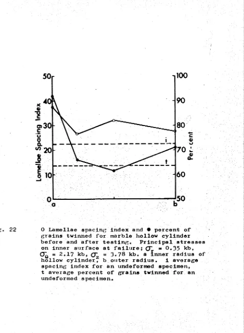
22
23
24
25
26
27
28
(ix) Follows
Page Trachyte hollow cylinder after extension and
fault failure 23
Marble hollow cylinder after an extension
fracture 23
Trachyte hollow cylinder after "collapse”
failure 23
Marble hollow cylinder after ’’collapse” failure 23 Trachyte hollow cylinder after conical fault
failure 23
Distribution of twinning in a marble hollow
cylinder before and after failure 26 OTj/0~2 curves for marble cylinders tested by
Boker and von Karman 27
O^/ 0~2 curves for sand and clay tested by Wu,
Loh, and Malvern 27
Results of solid and hollow cylinder tests on
concrete by Bellamy 27
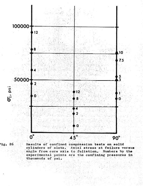
Results of confined compression tests on solid
cylinders of slate 42
Results of confined compression tests on hollow
cylinders of slate 42
Sketches of diametral compression specimens of
29
30
31
32
33
34
35
3 6
37
38
39
( x )
Follows Pa ge Sketches of solid cylinders of slate a f t e r
f a i l u r e 44
Sketches of hollow cylinders of s late a f te r
f a i l u r e 45
Coordinate system for hemispherically ended
borehole 54
Vertical s t r e s s in the rock near a hemispherically ended borehole due to a v e r t i c a l f i e l d s tr e ss 56 Stress in the rock near a hemispherically ended borehole due to a s t r e s s acting p a r a l l e l to the
borehole 56
Stress in the rock near a hemispherically ended borehole in a hydrostatic s t r e s s f i e l d 5 6
General view of s t r a i n ros e tt e r e l i e f
experimental apparatus 58
Experimental r e s u l t s of a s t r a i n r e l i e f t e s t
under an applied v e r t i c a l s t r e s s 6l Experimental r e s u l t s of a s t r a i n r e l i e f t e s t
under v e r t i c a l and longitudinal s t r e s s 6l Experimental r e s u l t s of a s t r a i n r e l i e f t e s t
under longitudinal s t r e s s 6l
(xi)
Figure Number
Follows Page 40 Calibration curve for borehole deformation gage 64 41 Variation of maximum and minimum principal
stresses with distance from the 14 Level cross
cut 87
42 Cross cut outline photograph at the 14 Level
stress measurement site 88
43 Dolomite “C11 axis orientation in an oriented
sample from 13 Level 90
44 Maximum principal stress directions determined from measurements of dolomite twin lamellae in
an oriented sample from 13 Level 90 45 Maximum principal stress directions determined
from measurements of dolomite twin lamellae in
an oriented sample from 13 Level 90 46 Dolomite "CH axis orientations in an oriented
sample from 14 Level
47 Maximum principal stress directions determined from measurements of dolomite twin lamellae in
an oriented sample from 14 Level 90 48 Minimum principal stress directions determined
from measurements of dolomite twin lamellae in
(xii)
Figure Follows
Number Page
49 Histogram of deformation moduli measurements 93 50 Histograms of in situ deformation moduli
measurements 94
51 Histogram of average in situ deformation moduli
measurements 94
Chapter I INTRODUCTION
The basic work undertaken in this thesis was a rock mechanics investigation of a portion of the Mt Isa mine, Mt Isa, Queensland, Australia* Both "in situ" measurements and laboratory tests were made* During the course of this study it was often necessary to
develop or at least investigate the various measurement, analysis, and testing techniques in the laboratory under controlled
conditions in uniform experimental materials before they could be applied with any confidence to the unkown and variable
conditions and materials found at M t . Isa. This development and testing work is presented as an integral part of the thesis, as the Mt Isa experiments could not proceed until the development w ork was done, and the analysis of the Mt Isa work depends in large measure upon these laboratory investigations*
The term "rock mechanics" has recently been defined by the Committee on Rock Mechanics of "the Geologic al Society of America in the following maimer:
"Rock mechanics is the theoretical and applied science of the mechanical behaviour of rock; it is that branch of mechanics concerned with the response of rock to the force fields of its physical environment*^
2
Workers in the subject, then, whether physicists, geophysicists, geologists, or engineers, are concerned primarily with two problems:
(1) determining the force fields of a particular physical environment, and
(2) measuring, understanding and perhaps predicting the response of the rock present to some
specified change in these force fields*
These two problems must be solved whether one is working on the mechanism of deformation of a fine grained monomineralic rock at high temperatures and pressures, trying to predict the occurrence
of the next major earthquake in an active fault zone, or designing a mining extraction sequence*
Rock mechanics as a science is quite young, certainly less than a century old* As an art it has been practiced by definition since the stone age* The overwhelming majority of scientific
papers and publications on the subject have appeared in the last
20 years arrL the definition of the subject given above was written only in 1963* Because the field is so new our fund of basic rock mechanics knowledge is still fragmentary and imperfect* Much of the applied rock mechanics work that is being done today must of necessity be based on poorly tested assumptions concerning both the force fields existing in nature and the response of rock
3
.
This particular rock mechanics investigation at Mt Isa was intended to be fairly complete and it included both measurements of the stress field acting in this portion of the mine and
measurements of the strength and elastic properties of the various rocks that are present. At nearly every step of the investigation it was necessary to retreat into the laboratory to make more basic investigations under controlled conditions. The first portion of the thesis, Chapters II through V, describes laboratory experiments on the failure of rocks under complex polyaxial stresses. The rock surrounding an underground
excavation is certainly not in a state of uniform uniaxial or triaxial compression or tension. The stress perpendicular to the surface of the opening is zero, (or really one atmosphere, approximately 14.7 psi. This will be taken as zero in both the laboratory and underground strength and stress measurements reported in this thesis). The other two principal stresses may be either tensile or compressive and may bear nearly any
relationship to each other. The failure criteria commonly used in rock mechanics have, however, in the main been derived from laboratory tests in which two of the stresses in a sample are held equal while the third stress is varied until the specimen fails. It has often been assumed (c.f. Brace [1964] , and
4
.
The experiments reported in Chapters II through V show that this assumption can be wrong, especially in stress fields similar to those around an underground opening.
Chapters VI through VIII deal with laboratory investigations of several stress measurement systems. These were full scale tests in which large blocks of rock were loaded to specified
stress levels and held there while the different stress measurement techniques were tried in the blocks. The results of the tests
were then compared with the known applied stresses. Full scale tests such as these were necessary because they were the only way that it was possible to study directly such problems as the effect of creep on flatjack measurements, or the effect of a stress
component acting parallel to the borehole axis on strain rosette relief techniques. The laboratory tests made it possible to study the use of flatjacks to measure an "in situ” modulus for rock
and also to empirically determine which of the different techniques of determining elastic moduli of rock gives the best value to use in analyzing the borehole deformation gage and borehole strain rosette relief measurements. In addition of course, many minor practical problems in equipment, techniques, and analysis were found and solved in the full scale laboratory tests and this made the underground work simpler and more efficient.
5
rocks collected at Mt Isa, The three stress measurement techniques studied in the laboratory were used at Mt Isa and the results are analyzed, compared, and discussed in Chapter X, Chapter XI gives a comparison, of the "in situ” and laboratory determined values of elastic moduli. The strength of the Mt Isa rocks determined by both the conventional uniaxial and triaxial tests, and some of
the more complex systems given in Chapters II through V, have been given in Chapter XII, and a general failure surface has been developed for the Mt Isa "silica-dolomite”,
Some of the work presented in this thesis was published as soon as it was completed. To avoid unnecessary duplication and bulk this work is introduced and briefly reviewed in short
6.
Chapter I I
THB FAILURE OF THICK WALLED HOLLOW CYLINDERS OF ISOTROPIC ROCK
I n t r oduc t i o n
A s e r i e s o f expe r i ment s on t h i c k - w a l l e d hollow c y l i n d e r s of
r o c k s u b j e c t e d t o s e p a r a t e l y c o n t r o l l e d and v a r i e d i n t e r n a l and
e x t e r n a l p r e s s u r e and a x i a l l o a d were performed. The immediate
o b j e c t o f t h i s work was t o e x p e r i m e n t a l l y map the ’’f a i l u r e
s u r f a c e ” i n p r i n c i p a l s t r e s s space of t h r e e d i f f e r e n t rocks to
see f i r s t i f such a unique s u r f a c e does e x i s t i n e a c h case and
second, i f i t does e x i s t , how c l o s e l y i t conforms to the v a r i o u s
’’f a i l u r e s u r f a c e s ” p r e d i c t e d by t h e commonly used f a i l u r e c r i t e r i a
such as Mohr, G r i f f i t h or t h e modified G r i f f i t h t h e o r y of
McClintock-Walsh. Hollow c y l i n d e r s were used because n e a r l y any
p r i n c i p a l s t r e s s r e l a t i o n s h i p a t f a i l u r e can be a t t a i n e d with
t h i s system. The specimens a r e e a s i l y p r e p a r e d and only minor
m o d i f i c a t i o n s need be made t o the u s u al simple t r i a x i a l t e s t i n g
equipment i n order t o perform t h e s e t e s t s . The s t r e s s e s i n the
sample a r e not homogeneous i n t h i s system, however, and must be
c a l c u l a t e d by e l a s t i c or e l a s t i c - p l a s t i c t h e o r y from the a p p l i e d
p r e s s u r e s and a x i a l l o a d . A l s o , s i n c e t h e s t r e s s e s a r e
inhoraogen/DUs, s t r e s s g r a d i e n t s e x i s t which i n themselves may
7
of end conditions or friction at the platens may be of more importance than in conventional triaxial compression tests on solid cylinders. These problems are very real and can not yet
be completely resolved. It is most important to make investigations of this type, however, as rock in nature and around engineering
works does not necessarily fail under uniform triaxial compression or extension stresses. Stress gradients on some scale will
nearly always be present and no two of the three principal stresses at a point of failure will in general be equal. It is clearly
impossible to study the effect of stress gradients or the relative value of the intermediate principal stress on the failure of rock unless experimental systems are used which allow these to be
varied.
The term ’'failure surface" is here used in the same sense as "yield surface" is in ductile materials, c.f. Nadai [jL950, except that most of these tests were performed in the brittle range of behaviour of the materials so that failure was mostly by fracturing with only minor amounts of yielding. This "failure
8
.
not to hold for the yield of ductile metals, c.f. Taylor and Quinney [l93l] and it has also been shown that it is not always valid for the brittle fracture of rocks or cast iron, Robertson £1955] » Grassi and Cornet [19^-9] • Variation of the intermediate principal stress appears to affect the strength of the rocks in the present series of experiments by upwards of several hundred per cent in some cases. Throughout this thesis compressive stresses will be reckoned positive and ^ 1 ^ 0~2 ^ . The term triaxial
will be restricted to the condition ^1 ^ ^ 2 = or the conventional confined compression test. Polyaxial will be used to describe
states of stress in which ^ @~2 jL ^3.
previous Work
Hollow cylinders of rock with axial load and external pressure have been studied by Adams [l912] , King [1912] ,
Bridgman [19I8J, Robertson [l955] » Obert and Stephenson [1965J and Jaeger and Hoskins [1966], (the work being included in Chapter III and appendix 2 of this thesis). Hobbs \i962] and Pomeroy and Hobbs [1962] have worked on coal. Bellamy [i960] has tested hollow cylinders of concrete and Wu et al [1963] and Broms et al ^1965j describe similar tests on soil materials.
compression have been extensively studied to determine their behaviour under combined stresses. Much of* this work has been
summarized by Nadai [l950, Chapter 17] .
Boker [l95l] and Handin, Higgs, and O ’Brien [i960] have performed experiments on solid cylinders of marble with
combinations of axial stress, torque, and confining pressure. Handin, Heard, and Magourik [1967] have tested thin walled
hollow cylinders of limestone, dolomite, and glass with combinations of internal pressure; external pressure, torque and axial stress at several strain rates and temperatures*
Paul [1961] , Marin [l966"] and Jaeger [1966] have given
recent theoretical discussions of the shape of the failure surface for brittle materials*
9
.
Stresses in a Hollow Cylinder
Let the external radius of the cylinder be b, the internal radius a, the internal pressure P ^ , the external pressure PQ , and the differential axial force applied by the testing machine P* The radial and tangential stresses C r and G~q at any radius r,
based on elastic theory are, Jaeger [1962J
, 2_ 2_
b p - a P . e______ x 0"r = 2 2
o - a
cr,
Q, 2- . 2_
b P - a P, e______ i
,2 2
b - a
a2b2 (p -P.) ____ v e i ' r2 (b2-a2 ) a2b2(Pe^Pi )
r2 (b2-a2 )
(1 )
10
The axial stress CT for the test geometry and apparatus z
used in these experiments is:
(3)
The distribution of radial and tangential stress through the cylinder walls for the two limiting conditions = 0 and = 0 is shown in Figures l(a) and (b). King [1912] has described the types of failure to be expected for different relative values of
0~T 1 0~q an<3 Q~z based on maximum shear stress failure criterion.
In some of these experiments, conducted with relatively high internal and external pressures, the stress distribution in the cylinders is probably not very well described by the equations of
equations based on simple plasticity first derived by Beliaev and Sinitskii for the stress distributions in hollow cylinders with external pressure and axial load. There are numerous treatments of the expansion of elastic—plastic cylindrical tubes in
connection with autofrettaging and pressure vessel design, c.f. Hill [l950» Chapter 5J • MacGregor et al jipU8j present a theory for the partial yielding of thick walled cylindrical tubes under internal pressure, external pressure, and axial load using von Mises yield condition. Wu et a 1 [1963] give a solution for the stresses in a hollow cylinder using a Mohr-Coulomb yield criterion. Jaeger discusses the various possible cases in some detail.
Fi g.
(a)
(b)
( a ) S t r e s s d i s t r i b u t i o n i n h o l l o w c y l i n d e r s 5 cm o u t s i d e d i a m e t e r b y 2 . 5 cm i n s i d e d i a m e t e r w i t h e x t e r n a l p r e s s u r e o n l y , a , i n n e r s u r f a c e t o b , o u t e r s u r f a c e .
11
The problem here is that the magnitudes of* the stresses calculated from the applied pressures and loads in the elastic-plastic
solutions depend on the yield criterion chosen and it is the form of the yield criterion that we are attempting to find with these experiments* It should be recognized that neither rocks nor very many other materials are perfectly elastic or elastic-plastic up to the point of rupture. Elastic theory was used to calculate the stresses in the experiments because it is the most reasonable
mathematical approximation to the behaviour of these materials in most of the tests*
Apparatus and Materials
The testing apparatus is shown diagrammatically in Figure 2* It basically consisted of a simple triaxial pressure cell and piston. The piston was hollow to allow the internal pressure to be applied and controlled independently. The rock specimens were
5 cm outside diameter, 2*5 cm inside diameter and 12 cm long.
They were jacketed both internally and externally with soft rubber tubing. Pressure was controlled through separate outlets on a hydraulic bench with needle valves and a screw press. Additional differential axial load was applied by an Avery 500 ton
12
placed between the paper and the anvils of the testing apparatus in an attempt to eliminate frictional restraints at the ends of the specimen. Several lubricants were investigated before
settling on this procedure. The main object was to find a material which would not inhibit any radial deformations that
the specimen tried to take without introducing other modifications of the stress distribution near the ends of the specimen or
intruding as a liquid into the ends of the specimen. Bowden and Tabor [1 9 6 4, Chapter Vll] give values for the coefficient of
sliding friction of various ionic brittle solids on steel from 0.4 to 0.9* They give a coefficient of sliding friction for
graphite on steel of approximately 0.1 so that the graphite should b© effective in reducing radial frictional restraints. The paper was placed between the rock and the graphite to preclude the
slight possibility of the graphite intruding into any open pores, grain boundaries, or cracks in the ends of the specimens under the
(up to 6.5 kb) end pressures reached in some of these tests. Xt is assumed that the paper has no significant strength and that it does not modify the stress distribution at the ends of the
hollow cylinder. Tests have been performed on solid cylinders of the same three rocks under confining pressure and with several different end lubricants and the results of these tests are
13
layer does not appear to affect the strength of solid cylinders of these rocks. Comparison tests were made on specimens with clean (wiped with acetone), dry, bare ends in direct contact with dry, hardened, steel end pieces of the same diameter. The axial load was applied through a spherical seat in all cases.
1
Due to the complicated geometry of the system the actual strain rates achieved are not accurately known. Additional load from the testing machine was applied to give axial strain rates
•"6 -7 JL
of between 10*” and 10~' sec"* during the linear portions of the stress strain curve.
The three rock types tested were:
(1) Bowral "trachyte”. This is the commercial name for a rock that has been more accurately described by Joplin [l964] as an altered micro-syenite. It is an even-grained, isotropic igneous rock consisting predominantly of orthoclase and aegerine-augite 1 mm in grain size with minor amounts of quartz, calcite, and altered ferro-magnesian minerals.
(2) Gosford Sandstone. A very uniform, isotropic, fine-grained, weakly cemented, quartz sandstone with a sugary texture.
l4.
Failure Criteria
Nadai [l950] > Jaeger [1962] , [1963] » and [1966] and Marin ["1966^ have given reviews of the various commonly used failure
criteria for brittle materials* Of these the octahedral shear
stress or distortional energy failure criterion and the three stress dimensional generalizations of Griffith and modified
Griffith failure criteria predict the dependence of the ultimate strength of a sample on the relative value of the intermediate
principal stress. The distortional energy or octahedral shear
stress criteria much used for the yield of metals under combined stresses predicts the same strengths in tension and compression. In terms of invariants the yield strength depends only on the
invariants of stress deviation and not on the invariants of stress. Since the measured strength of rock is lower in tension than in compression, the distortional energy criterion cannot be expected to be applicable to rocks unless all three principal stresses are
of the same sign. In practice the rock must deform plastically
as only then does its strength appear to be independent of the stress invariants.
Murrell £1963] and [1966j and Jaeger [196 6 ] have given and
discussed a three dimensional treatment of Griffith theory. The
"failure surface" derived on this basis is a paraboloid of
15
thorough the o rig in . In terras of* p rin c ip a l str e ss e s the equation of* th is surface is
( ° i - ° 2 ) 2 + (~cr2 - 0 j ' ) Z * fcnj-op2 = 24 To
(cr1+o^+c^)
(4) where T i s the uniaxial te n sile strength. From th is i t can beo
shown tha t the uniaxial compressive strength, CQ, should be -12Tq. The in te r s e c tio n of t h i s surface with any given s tr e s s plane can e a s i ly be found. For example, the in te r s e c tio n of the surface with the plane representing the conditioner^ = 0 i s an e llip s e
(c^ -ct, ) 2 + cr22 + 0 - J 2
= 24To(cr1+cr2)
(5)Hollow cylinders te s te d with external pressure and a xial load
only are t e s t s in which (7^ = 0 a t f a il u r e (assuming f a ilu r e occurs on the inner surface). I f t h i s three dimensional G r if f ith
c r i t e r i o n is valid then these hollow cylinder t e s t r e s u lt s should f a l l on t h i s e l l i p s e .
Jaeger [1 9 6 6J has proposed regarding the t r i a x i a l t e s t r e s u l t s as a fundamental measure of a ro c k ’s p ro p e rtie s. In
other words, the t r i a x i a l r e s u l t s give the in te r s e c tio n of the f a il u r e surface with the = Q~ plane for that p a rtic u la r rock regardless of f a il u r e mechanism or mechanisms acting. A complete f a il u r e surface might then be generated by r o t a ti n g a curve
f i t t e d to the t r i a x i a l t e s t r e s u l t s about the lin e - 0~2 = CJ^* I t was simpler and more i l l u s t r a t i v e for the purposes of this
16
point to the particular sections plotted. Using Jaeger*s notation this is done by means of equations (6) and (7)
CT^ + 2CT. = °1 + 0~2 * CTj (6)
2(criT-°3T >2 =
@~
2<r3)z
+(o~
3-oi
)2 + (G-1-05)2 (7) where (X andQ~
are the maximum stress at failure and theT JT
confining pressure from the conventional triaxial tests. If the triaxial points are rotated to the
(J~^
= 0 section of the failure surface for example they should fall on the same curve as the hollow cylinder tests conducted with = 0 if this criterion is valid.The McClintock-Valsh modification of Griffith theory to account for the effects of friction in the Griffith cracks under compressive stresses can similarly be rotated and made into a three stress
dimensional criterion. In two stresses it can be written
°i [(1+^2
- °~2 [h^x2)V ] = i
»To
[l+cg/Tj
* -
(8)
where
jX
is the coefficient of sliding friction in the crack surfaces and CT is the stress required to close enough of the cracks farc
17
stress region by a paraboloid the 07, = 07^ section of which is determined by the original Griffith theory. The magnitude of 07 »
c the stress required to close the cracks, has been variously taken as -3Tq by McClintock and Walsh [1962] , zero by Brace [196ÖJ and -4.19Tq (an experimentally determined value) by Murrell £1 9 6öj . There are two difficulties here, one, the crack length and shape are not accurately known and two, complete closure is apparently not required. -T was used in the present work not implying any fundamental relationship but merely as a small convenient quantity which seems to fit the trachyte data. The coefficients of friction,
jJL, for each of the three rocks used were experimentally determined using the techniques given by Jaeger [l959j^ for sliding friction on experimentally formed fracture surfaces and were found to be trachyte = 0.80, sandstone = 0.66, and marble = 0.90# These values are constant over the range of normal stresses of interest here.
In principle, any failure criterion which can be plotted in terms of principal stresses can be rotated in a similar manner and made into a three stress dimensional failure criterion.
Figure 3 is a drawing of the three dimensional failure surface for Carrara marble. This surface was developed by rotating the triaxial test results which lie on AB about the = 0~2 = axis. The experimental results lie between OAB and ODC and fit this
c
Fig* 3 Drawing of the three dimensional failure surface for Carrara marble. The conventional triaxial compression tests with = (X, fall on A B. Extension tests with = CT; lie on ODC. Tests
18
Experimental Results
Because of the lack of a generally accepted means of
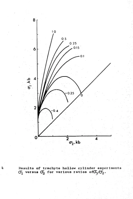
presenting these data, the results of the experiments are given in three forms. The values of the principal stresses on the inner surface of the cylinder calculated by elastic theory for each test are given in Tables I, IX, and III. Figures 4, 5> and 6 are graphs of Ö~1 versus G~2 for various ratios of C7^/G^ for the three materials.
In addition several sections of the failure surface for each rock type are given in Figures 7-15 along with the envelopes in the section representing three of the failure criteria which might be applicable•
Turning first to Figures 4, 5» and 6 the CT^/tTj? ratio of 1.0 represents the conventional triaxial compression tests. The other curves represent tests conducted on hollow cylinders with tire applied pressures arranged so that by various amounts. In practice, the experiments are performed with Pa P , the
principal stresses at failure are calculated and plotted and smooth curves are interpolated among the experimental results.
This is a simple means of presenting the data from all of the tests on a particular experimental material on a single diagram. It is difficult to show individual test results or to compare the
experimental results with the different failure criteria on these diagrams, however. Figures 7 through 15 are included to
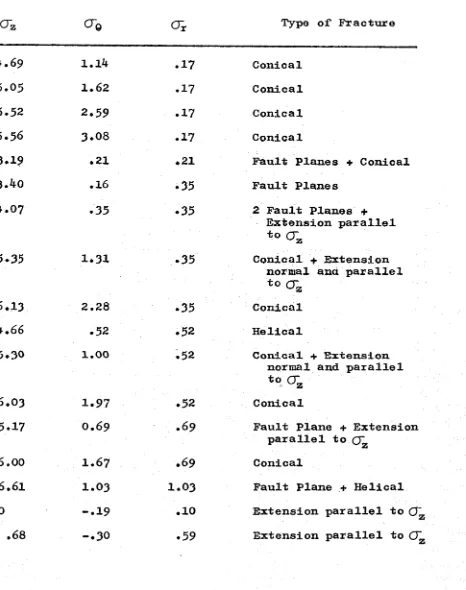
Table I
Principal stresses at failure on inner surface of trachyte hollow cylinders calculated on elastic theory and type of fracture observed in each case
O o Type of Fracture
1 . 6 3 0 0 Fault Plane + Extension
parallel to 0~z
2 . 2 9 . 1 9 0 Conical
2 . 5 3 . 3 ^ 0 Conical
3 * 0 0 . 4 6 0 Conical
3 . 3 0 . 7 7 0 Conical
3 . 5 1 . 9 7 0 Conical
3 . 8 9 1 . 4 5 0 Conical
3 . 9 2 1 * 9 3 0 Conical
4 . 4 o 2 . 3 2 0 Conical + Extension
parallel to CT
z
4 . 0 6 2 . 4 2 0 Collapse
3 . 3 9 2 . 7 0 0 Collapse
3 . 6 2 2 . 9 0 0 Collapse
2 . 7 6 3 . 3 8 0 Collapse
2 . 5 7 3 . 6 2 0 Collapse
2 . 6 2 3 . 8 6 0 Collapse
2 . 5 9 . 1 7 . 1 7 Fault Plane + Conical
3 . ^ 7 . 4 6 . 1 7 Fault Plane + Extension
normal to C z
Table X (continued) CTZ 4.69 5.05 5.52 5.56 3.19 3.40 4.07 5*35 6.13 4.66 5.30 6.03 5.17 6.00 6.61 .68
CT-e O r Type o f Fracture
1.14 .17 Conical
1.62 .17 Conical
2.59 .17 Conical
3.08 .17 Conical
.21 ♦ 21 Fault Planes + Conical
.16 .35 Fault Planes
.35 .35 2 Fault Planes +
Extension parallel to crz
1.31 ♦ 35 Conical + Extension
normal ana parallel to rr
2.28 .35 Conical
.52 .52 Helical
1.00 .52 Conical + Extension
normal and parallel to crz
1.97 .52 Conical
0.69 .69 Fault Plane + Extension
parallel to (j
1.67 ♦ 69 Conical
1.03 1.03 Fault Plane + Helical
-.19 .10 Extension parallel to CT
1
.
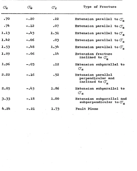
0 .59 Extension parallel to (J~_ [image:35.516.27.493.83.673.2]Table I (continued)
0~z 0 © CTr Type of* Fracture
.70 - . 2 0 .22 Extension parallel to
.74 -.12 .07 Extension parallel to Q~
1.13 -.43 1.31 Extension parallel to G~z
1.42 1 • O On .03 Extension parallel to 0~z
1.53
0
0
•
1
1.3^ Extension parallel t oO'
1.89 -.06 .14 Extension fracture
inclined to O' z
1.96 -.03 .12 Extension subparallel to
crz
2.22 -.16 .52 Extension parallel
perpendicular and inclined to O'
z
2.85 -.45 1.86 Extension subparallel to
O z
3.33 -.18 1.00 Extension subparallel and
subperpendicular to O"z
[image:36.516.18.501.81.680.2]Table II
Principal stresses at failure on inner surface of marble hollow cylinders calculated on elastic theory and type of fracture observed in each case
<xe Type of Fracture
0 . 8 0 0 0 Fault Plane + Helical +
Extension parallel to O'z
1 . 5 4 . 4 6 0 Conical
2 . 0 3 . 9 3 0 Conical
2 . 3 9 1 . 3 8 0 Conical
2 . 5 9 1 . 8 4 0 Conical
2 . 8 2 2 . 3 0 0 Conical
2 . 7 1 2 . 7 5 0 Collapse
H
H
•
H
. 0 7 . 0 7 Helical
1 . 6 3 . 4 4 . 0 7 Helical
2 . 1 4 . 8 0 . 0 7 Conical
3 . 0 2 1 . 7 2 . 0 7 Conical
3 . 2 8 3 . 0 9 . 0 7 Conical
2 . 1 3 . 3 5 . 3 5 Fault Plane
3 . 7 8 2 . 1 7 . 3 5 Conical
2 . 3 8 . 5 0 . 5 0 Conical
3 . 1 8 . 6 9 . 6 9 Fault Planes
3 . 9 7 1 . 6 7 . 6 9 Conical
H
H
Table II (continued)
CTz CTO
crr
Type of Fracture• 34 -.09 .05 Extension parallel to 0~z
.79 -.09 .32 Extension parallel to 0~z
• 59 -.18 .36 Extension parallel to (J~
z
.69 0 .54 Extension parallel to Q~z
.57 -.15 .76 Extension parallel to 0~z
1,09 -.24 1.21 Extension parallel to 0~z
2.0 6 -.11 1.24 Fault Plane + Extension
[image:38.516.41.495.92.685.2]Table III
Principal stresses at failure on inner surface of sandstone hollow cylinders calculated on elastic theory and type of fracture observed in each case
<Xe crr Type of Fracture
. 4 9 0 0 Helical
. 6 7 On
O
• 0 Conical
o
0
0
• . 1 8 0 Conical
1 . 0 8 . 4 6 0 Conical
1 . 1 2 . 7 7 0 Conical
1 . 2 9 . 9 2 0 Conical
1 . 0 0 1 . 1 6 0 Collapse
1 . 2 1 1 . 3 7 0 Collapse
. 7 3 1 . 4 5 0 Collapse
1 . 1 4 1 . 4 7 0 Collapse
0
0
• 1 . 6 6 0 Collapse
. 00 1 . 7 4 0 Collapse
o
0
0
. . 0 7 . 0 7 Conical
1 . 1 5 . 4 5 . 0 7 Conical
1 . 4 2 .62 .07 Conical
1 . 5 3 . 8 0 . 0 7 Conical
1 . 5 9 1 . 0 7 . 0 7 Conical
1 . 8 5 1 . 3 3 . 0 7 Conical
1 . 8 4 1 . 4 2 . 0 7 Conical
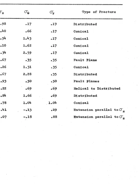
Table III (continued)
crz o-# Oi
00
o
\
•
.1 7 .1 7
1 .4 0 .6 6 .1 7
1.5^ 1 . ^ 3 .1 7
2 .1 0 1 . 6 2 .1 7
2 .3 4 2 . 3 9 .1 7
1 . 6 7 .3 5 .3 5
2 .2 6 1 . 3 1 .3 5
2 . 6 7 2 . 2 8 .3 5
1 .9 3 .5 0 .5 0
2 .2 2 .6 9 .6 9
2 .8 4 1 . 6 6 .6 9
2 . 7 8 l.o4 1 .0 4
.4 1 - . 1 3 .2 9
1 .0 7 - . 1 8 .8 8
Type of Fracture
Distributed Conical Conical Conical Conical Fault Plane Conical Distributed Fault Planes
Helical to Distributed Distributed
Conical
Extension parallel to (J~z
[image:40.516.29.502.66.690.2]8
Fig. It
L
10
,-025
Results of trachyte hollow cylinder experiments
[image:41.516.65.503.36.689.2]0.025
<-025
Results of sandstone hollow cylinder experiments. (T^ versus 0~2 for various r a t i o s cfCT^/O^»
lifT. 7 Results of trachyte hollow cylinder experiments conducted with QTj = CT^ plotter! in terms of the unconfined compressive strength C . "A" represents the McC1int ock-Wa1sh failure criterion plotted in the 0~n s CT section of the failure surface with coeffreient of friction jj, = 0.80 and the stress
required to close the Griffith cracks Q~ taken
equal to T . "B" represents the three dimensional Oriffith tfieorv failure criterion in the CTn = Q~^
8
0 --- -— --- ---1---1---1
2
4
(®2
/Co-O^/CoJv^-I'i^, H Results of marble hollow cylinder experiments
conducted with = CJ"~ plotted in terms of the
V i r , . 9 Results of' sandstone ho 1 low cylinder e x p e r i m e n t s conducted with (X, =
O'
plotted in terns of the unconfined compressive strength C • "A" r e p r e s e n t s the McClintock-Walsh failure criterion plo t t e d in the CX, = (X, section of the failure s u r f a c e with a c o e f f i c i e n t friction of O.06 and Q ~ = T . "H"represents the three dimensional d r i f f i V h failnre c r i t e r i o n in the (X> = ( X section. "f" repre •> r * - tiie distor tional ener f^yJfa i lure c r i t e r i o n in '' > > •
19
in the diagonal plane of* the three dimensional failure surface
of each of the three rock types« This is the section which
contains the usual triaxial compression tests* The experimental points are given and may be compared with curves representing the distortional energy, three dimensional Griffith and the three dimensional version of the McClintock-Walsh modification of Griffith failure criteria. None of these criteria are valid for all three of the rocks investigated. Figures 10, 11, and 12 are the oblique sections of the failure surface in which = 0, The intersections of the same three failure criteria with the <j~^ = 0 plane are plotted in these diagrams along with results of hollow cylinder tests in which = 0 at failure (P^ = O), Xn addition, the triaxial test results have been rotated into this section by means of equations (6) and (7)* The sandstone results given in Figure 12 show a great deal of scatter at the higher values of 0~0/C , These were tests in which OT>XT at failure and the failure occurred by a sudden violent inwards collapse of the specimen walls. The failure appeared to be time dependent in these tests and the plotted stresses which are
calculated on simple elastic theory are probably inaccurate. Figures 13» 14, and 15 are oblique sections of the failure surfaces when G ^ / C Q - 0,1, In these diagrams the experimental scatter is much reduced. Here again the intersections of the
three theoretical failure criteria with this plane are given along
with hollow cylinder test results in which (X,/C - 0,1 and the
°2/Co
10 Trachyte hollow cylinder tests when 0Z = 0. 0
Hollow cylinders witli internal pressure = 0, • hollow cylinders with internal pressure = to
the external pressure or (X, = Q~ when rotated about the
(X
=(X
=(X
axis into the(X =
0section. "A" M c H U ntoclc-Walsh failure cri t.orion rotated into the (X = 0 plane, "R" three
dimensional Griffith thoory rotated into the
Fi/T.
^2/Co
Marble h o l l o w cylin d e r tests w h e n QZ. = >. G
Hol l o w c y l i n d e r s w i t h 1* = 0 . • H o l l o w c v l i m l e i s ~ or (X0 = CTo w h e n i otated a bo > t t' e
a x i s ^ i n t o the Q ~ = 0 section. "A" alsli fa i l n r e r r i f e r i o n r otated into the Q ~ = 0 plane, "D" three d i m e n s i o n a l Griff it theory in the Q ~ = 0 plane, and "G" tlie
d i s t o r t i o n a l e n e r g y fai l u r e c r i t e r i o n in the OTj = G plane.
w n n r . a , - o ~ o
McC lin?ock-ti
6
Fi^.
° 2 / C 0
0. • T lollop evil rider S a n d s t o n e h o l l o w c y l i n d e r tests wlien (J,
" o l 1ow c y l i n d e r s with w i t h P
o ; = c j o
o.
P or
CT,
=O~o
w h e n r o t a t e d about the ^ - kj 2 ~ 0"^ ax:*-s ^ i n t o ilie (To = 0 section. "A"M c C l i n t o c k - w a l s h f a i l u r e c r i t e r i o n r o t a t e d into the 0~3 = 0 plane, "IV* t h r e e d i m e n s i o n a l Grif f ! th theory in the 0~3 = 0 plane, and "C" tlie
6 A
Fig.
I
13
o
u
\
b~
° 2 / C o
Trachyte hollow cylinder tests when (X, = 0.106 a tr _ 1 i ____ ____ 1 j ____ I ______ . . j i t . n a i r \ £ a J a i r . 1 1
0 Hollow cylinders with P _ cylinders with P, = P_ o r \ X about the C7~i = Q~
0.106 C # Hollow _ , w* v 2 - 0 1 when rotated
-KJ 2 = CJ^ axis into^theCT- = 0.106 Cq
section of the failure surface. nA" McClintock-0.106 eory Walsh failure criterion rotated into the 0 “~ C plane, f,B M three dimensional Griffith tn
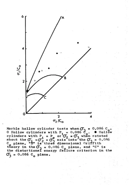
Fig. 14 Marble hollow cylinder tests when O"o = 0.086 C • 0 Hollow cylinders with P^ = 0.086 • Hollow cylinders with P. = p or (T? * CTo when rotated about the O', = (J~Z = (J? axis i n t o r h e (To = 0.086 C plane, "B" is three dimensional Griffith
[image:52.516.87.505.63.663.2]Fig. 15 Sandstone hollow cylinder tests whenQ". = 0.1*i C q . 0 Hollow cylinder tests with P. = 0.1** C Q . • Hollow cylinders with P^ ss P0 or (J‘p = (To when rotated about the ( L = 0~2 = 0~o axis into the
(31 = 0. l4 C section of the failure surface. "A” is the McCl?ntock-Walsh failure criterion rotated into the 0" = 0.1** C plane, "TV* is three
dimensional Oriffith°theory in the 0 1 = 0.1*1 C plane, and "CM is the distortional energy failure criterion in the 01 = 0.1*1 C plane.
[image:53.516.32.507.77.676.2]20
position of the triaxial test results when they axe rotated into this same section.
Nature of the Fracture
King £l912j has given the types of fracture to be expected in hollow cylinders based on the maximum stress difference
failure criterion. Robertson [l955j and Jaeger [1966J give further discussions of his treatment and Robertson loc. cit. and Jaeger and Hoskins £1966
J
(and in appendix 2) have compared their results of tests on hollow cylinders with external pressure and axial load with the types of failure predicted by King*Since the maximum stress difference or maximum shear stress
failure criterion takes no notice of stress sign only three stress conditions and families of fracture surfaces are possible. The strength of rock specimens is considerably lower in tension than in compression, however, and in some of the experiments in this investigation in which the internal pressure exceeded the
external pressure tensile stresses were developed and these
governed the failure rather than the compressive or shear stresses. If the positive compressive stress sign convention is used, six different arrangements of principal stresses at failure can be written:
(1) crz >O-
0?o-r
21
(3) crö>crz >crr
(*0 crr >crz >cre
(5) crz>crr >cre
(6) ö-9>crr7<Tz
Combinations ( l) and (2) based on King1s analysis give a s et of cone shaped fractu re surfaces, (3) and (4) a s et of equiangular s p i r a l fra c tu re s which Robertson \jL955~] called
hinged trap door f a i l u r e , and (5) and (6) y ie ld a set of h e lic a l f ra c tu re s which give r i s e to the commonly observed Luder's lin e s on the outer surface of the specimen. Of these, combinations
( l ) , (3)» (4) and (5) were achieved in t h i s serie s of t e s t s , Griggs and Handin [1960J recognized two types of fra c tu re s ,
(a) extension fra c tu re s or the separation of a specimen across a surface perpendicular to the d ire c tio n of minimum p rin cip al s tr e s s without
offset p a r a l l e l to the fra ctu re surface and (b) f a u lts which are localized o ff s e ts p a r a l l e l to
a more or less plane surface of non-vanishing shear s tr e s s th a ts surface may be inclined at from 45° to a few degrees to the d ir e c ti o n of maximum p rin cipal compressive s tr e s s in
homogeneous m aterials.
by the presence of powdered rock on the fault surface. In some cases slickensides and fault steps were also well developed, the fault steps invariably opposing the direction of motion.
In addition experimental fractures can be divided into primary and secondary types. Primary fractures result from the
stresses applied to the sample in its more or less original state and secondary fractures resulting from either continued
deformation of the already failed specimen or dynamic loading due to the release of the stored elastic energy of the testing
machine. In this series of tests an attempt was made to limit the development of secondary fractures by unloading the specimen as soon as there was an indication of the impending collapse of the specimen. In a few cases repeat tests were made in which total collapse was permitted allowing some direct comparisons to be made. It was not possible to control the failure of the specimens that collapsed inwardly as this was a violent, almost explosive phenomena, and complete control in any case is very difficult unless an extremely stiff testing machine is used.
A possibly separate type of secondary fracture is what Borg and Handin \l966~] term a release fracture. These are extension fractures formed perpendicular to the direction of maximum compressive stress. They are thought to develop as a result of differential expansion during release of differential
stress and/or confining pressure. If so, they may be associated
2 3
.
with the secondary changes in length of experimentally deformed
Tables I, II and III give the types of fractures observed in each test for each rock type for the different principal stress relationships at failure which were achieved. Figures 16, 17» 18, 19» 20 and 21 are examples of variously fractured specimens illustrating each of the major types. Transitional examples occurred when the cylinders were near to failure in both extension and compression. As an example, in a marble hollow cylinder in which the stresses on the inner surface at failure were CT = 2.06 kb, Q~ = 1.24 kb and Ol = -.111 kb, a
Z 1 ^
fault plane, extension fractures perpendicular to CTq and
helical fracture traces were all present in the cylinder after completion of the test.
The cylinders which failed by collapse deserve special mention. This was a sudden and extremely violent phenomena
in all three rock types. Usually one-half to two-thirds of the height of the cylinder collapsed inwardly on equiangular spiral
fracture surfaces. The hole in the remaining cylindrical portion was filled completely with densely packed powdered
Fig* 16 Trachyte hollow cylinder after fault plane failure. Stresses on inner surface at failure from equations (l)# (2) and (3)> O' = 0.69 kb, <J-Q = 0.69 kb, and <jy = 5.17
Fig, 17 Trachyte hollow cylinder after extension and fault failure showing the development of extension fractures perpendicular to the maximum principal stress. Stresses on inner surface at failure from equations (l), (2)
Fi g* Carr ar a marble a f t e r an e x t e n s i o n f r a c t u r e * S t r e s s e s on i n n e r s u r f a c e a t f a i l u r e from e q u a t i o n s ( l ) , (2) and (3)> Q~r = +0*5^»
Ö
q= °» <X
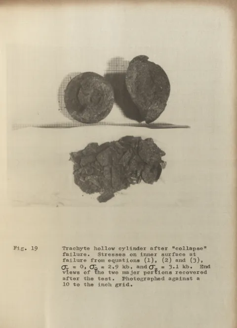
= +0*69* Photographed a g a i n s t a 10 to the i nch gri d*Fig. 19 Trachyte hollow cylinder after "collapse”
failure. Stresses on inner surface at
failure from equations (l), (2) and (3)»
QZ = 0, Oq = 2,9 k b , and Q ~ = 3.1 kb. End
views of the two major portions recovered
after the test. Photographed against a
[image:61.516.23.503.10.673.2]Fig* 20 Carrara marble specimen after a collapse or trap door type of failure. Stresses on inner surface at failure from equations
(1), (2) and (3), O ' = 0, = 2.75 Kb, and
Fig, 21 Trachyte hollow cylinder after conical fault
failure. Stresses on inner surface at failure
from equations (l), (2) and (3), CT = 0,17 kb,
0~q = 2*59 kb, and Q~ = 5*52 kb. Photographed
2 4.
the inner surface of the cavity apparently with great velocity. In the case of Bridgman's experiments, this powdered material completely filled the cavity creating eventually an internal
back pressure due to the increase in volume of the broken material and this internal pressure then inhibited further failure. In a few cases in the present investigation an experiment was stopped just short of failure and the specimen unloaded and inspected.
Only a small amount of spalling had occurred with the dozen or so spalled particles being flake-like in shape and a few
millimeters in diameter. When the specimens were subsequently reloaded they failed by collapse at only a slightly higher stress and when recovered the portion which did not collapse was
tightly filled with mostly fine, approximately equi-dimensional angular particles plus a few much larger fragments. When this material was dug out of the cavity, the cavity walls were found to be unmarked over most of this area. It seems clear that the majority of the powdered material in these cases did not come from spalling but from the almost explosive disintegration of the collapsed portion of the cylinder. The elastic strain energy density in a trachyte hollow cylinder which collapsed under an external pressure of 1*38 kb was approximately 4 x 10 J ergs/cc. This may be compared with estimates of the strain energy/unit volume liberated by rock bursts in deep mines of from 0.38 x 10 ergs/cc to 38 x 1 0 ^ ergs/oc, c.f. Duvall and Stephenson [l966j .