Int. J. Electrochem. Sci., 13 (2018) 305 – 314, doi: 10.20964/2018.01.05
International Journal of
ELECTROCHEMICAL
SCIENCE
www.electrochemsci.org
Periodic Change in the Ni Content in a Co-Ni Thin Film
Electrodeposited Using a Rectangular Pulse Current over a
Megahertz Frequency Range
M. Saitou
University of the Ryukyus, Department of Mechanical Systems Engineering, 1 Senbaru Nishihara-cho Okinawa, 903-0213, Japan.
E-mail: [email protected]
Received: 21 September 2017 / Accepted: 19 October 2017 / Online Published: 1 December 2017
Co-Ni thin films electrodeposited using a rectangular pulse current over a megahertz frequency range were investigated. Energy dispersive X-ray spectroscopy identified a resonant frequency at which the Ni content in the Ni thin film had a maximal value. A periodic change in the Ni content in the Co-Ni thin film emerged at a constant resonant frequency interval of 0.1 MHz between the neighboring resonant frequencies. X-ray diffraction analysis showed that a Co-Ni thin film containing more than 33 wt% Ni had a face-centered cubic (FCC) crystal structure, and that containing less than 28 wt% had a hexagonal close-packed (HCP) crystal structure. This indicated that the phase transition between the FCC and HCP structures occurred at the critical Ni content. The periodic change in the Ni content in the Co-Ni thin film was explained by an energy level transition of electrons that caused a resonant generation of Co and Ni.
Keywords: Co-Ni thin film; Energy level transition; Resonant frequency; Resonant frequency interval; Phase transition; FCC; HCP
1. INTRODUCTION
Co-Ni thin films have been studied because of their wide applications in magnetic tunnel junctions [1-2] and micro electro mechanical systems [3], and their advantageous wear performance [4] and corrosion resistance [5]. Electrodeposition is an attractive technique to form Co-Ni thin films because it provides advanced control of the physical properties of the film [6]. Many studies were performed to clarify the influences of the electrochemical parameters on Co-Ni film formation [7-8].
transition from HCP to FCC occurs at room temperature is not consistent among the reported phase diagrams [10-12]. A relationship was reported between the Ni content and the crystallographic structure for electrodeposited Co-Ni thin films [13-14]. A change in the crystallographic structure from HCP to FCC caused by an increase in the Ni content was qualitatively consistent with the phase diagram. In addition, the Co content in the electrodeposited Co-Ni film was much higher than the Co content in the electrolyte, which is called an anomalous deposition [7, 14]. In this study, we discuss anomalous deposition with respect to the reaction rate [15].
During Ni electrodeposition using a megahertz frequency, a resonant frequency and a resonant frequency interval between neighboring resonant frequencies were reported [16]. The resonant electrodeposition was interpreted as an energy level transition from the Fermi energy level of electrons in the electrode to a quantized rotational energy level of a Ni and sulfamate ions in the solution. The resonant frequency interval was 0.2 MHz.
When divalent Co ions with a mass close to that of the Ni atom are added to a solution containing Ni ions, the resonant frequency interval is expected to change. In addition, if resonant electrodeposition occurs during Co-Ni co-electrodeposition, the Ni content in the Co-Ni thin film will also largely change with respect to the frequency. This is our motivation for the present study in which we clarify the origin of the resonant frequency and the resonant frequency interval during Co-Ni electrodeposition, and the FCC to HCP phase transition.
The aims of the present study are to show the periodic change in the Ni content in the resonantly generated Co-Ni thin film, the presence of the resonant frequency interval, and the phase transition from HCP to FCC with an increase in the Ni content in the Co-Ni thin film.
2. EXPERIMENTAL SETUP
A copper plate of 30×10 mm2 and carbon plate of 50×40 mm2 were used for the cathode and anode. One side of the copper plate was electrically insulated so that deposition would only occur on the opposite side. Two aqueous solutions including the following chemical compounds (mol L-1) were prepared: solution A, NiSO4・6H2O (0.709); CoSO4・7H2O (0.236), and KNaC4H4O6・4H2O (0.65); solution B, NiSO4・6H2O (0.475), CoSO4・7H2O (0.475), and KNaC4H4O6・4H2O (0.65).
The two electrodes cleaned using a wet process were placed parallel to each other in an electrochemical cell filled with aqueous solution A or B. The solution was kept at 300 K during the electrodeposition.
The Co-Ni thin film was electrodeposited on the copper plate immersed to 15 mm in depth in the solution. As the area of the carbon electrode was about 27 times larger than that of the deposited area of the copper plate, the impedance in series of the carbon electrode in the solution can be neglected.
frequency below 80 MHz. The rectangular pulse current carried in the electrochemical cell was calculated from a voltage drop across the metal film resistor, which was measured using a digital storage oscilloscope (Yokogawa DL1720).
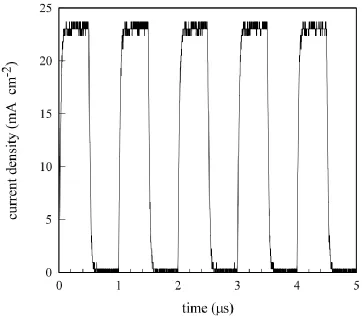
Figure 1. Rectangular pulse current with an amplitude of 23 mA cm-2 and frequency of 1 MHz. The amplitude of the rectangular pulse current was calculated from the voltage drop across the metal film resistor.
Figure 1 shows a typical rectangular pulse current with an amplitude of 23 mA cm-2 and frequency of 1 MHz, which was measured during electrodeposition using solution A. The rectangular pulse current was chosen with equal on and off-times.
After deposition, the Co-Ni thin film electrodeposited on the copper plate was rinsed with distilled water and dried in a vacuum chamber. The Co-Ni thin film was weighted to a precision of 0.1 mg with an electric balance (AND HR-60) to calculate the film thickness of the Co-Ni thin film.
[image:3.596.112.474.145.464.2]
3. RESULTS AND DISCUSSION
[image:4.596.130.465.150.478.2]3.1. Co-Ni thin films electrodeposited in solution A
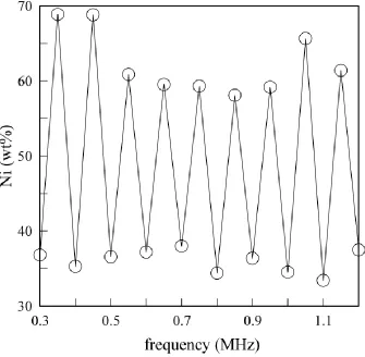
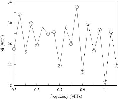
Figure 2. Frequency-dependence of the Ni content in a Co-Ni thin film electrodeposited in solution A.
Figure 2 shows the dependence of the Ni content in the Co-Ni thin film on the frequency. The Ni content periodically changes with the frequency and has a maximal value at the resonant frequency. The resonant frequency interval between the neighboring resonant frequencies is 0.1 MHz
We previously reported that the deposition mass of Ni periodically changes with the frequency during Ni electrodeposition [16]. The frequency-dependence of the Ni deposition mass was explained by the energy level transition between an electron at the Fermi energy level in the electrode and a Ni ion characterized by a quantized rotational energy level. The energy level transition causes a maximal deposition mass of Ni at the resonant frequency. The resonant frequency interval between the resonant frequencies in Ni electrodeposition is 0.2 MHz.
The deposition mass of Co is also expected to change with frequency. Hence, the Ni content in the Co-Ni thin film periodically changes with frequency. The lowest transition energy spacing of a linear molecule comprising a Ni ion and tartaric ion becomes [16],
where ħ is Planck’s constant, I is the moment of inertia (I=r2 where is the reduced mass and r is the distance from the pivot point). During Ni electrodeposition, we set the energy of the electron that is obtained by passing through the electric double layer as . Eq. (1) can be rewritten for Ni electrodeposition,
(2) where f is the resonant frequency interval.
On the other hand, the molecular weight of Co is almost the same as that of Ni. The number of electrons required for co-electrodeposition of Co and Ni is two times larger than that for Ni electrodeposition. An electron passing through the electric double layer in the co-deposition obtains half as much energy as that in Ni electrodeposition. Eq. (2) can be rewritten for Co and Ni electrodeposition,
(3)
where is the resonant frequency interval in the co-electrodeposition. Hence, we have Thus, the resonant frequency interval in the Co-Ni film will be half the value of that in the Ni film.
As shown in Fig. 2, the Ni content changes from 33 to 69 wt%. This makes it possible to generate a Co-Ni thin film containing a specified Ni content even if the appropriate frequency is chosen.
[image:5.596.99.499.417.698.2][image:6.596.63.537.262.437.2]
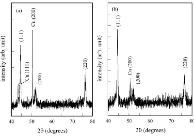
Figure 3 (a) and (b) show XRD patterns for two Co-Ni thin films: a Co-Ni thin film electrodeposited at 0.35 MHz containing 69 wt% Ni, and a Co-Ni thin film electrodeposited at 1.1 MHz containing 33 wt% Ni. The diffraction peaks are indexed as the (111), (200), and (220) planes, which are consistent with those in another study [17]. The crystal structure is FCC for both Co-Ni thin films. The XRD analysis concludes that the Co-Ni thin film is an alloy comprising Co and Ni. All the diffraction peaks in Fig. 3 are broad, which suggests that the Co-Ni thin film is composed of small grains. We estimate the mean grain size d using the Scherrer equation [18], where K is the shape factor, is the X-ray wavelength, and isthe line broadening of Bragg diffraction B. We obtain mean grain sizes of 22 nm and 21 nm from the diffraction peaks (111) in Fig. 3 (a) and (b) using K=1.
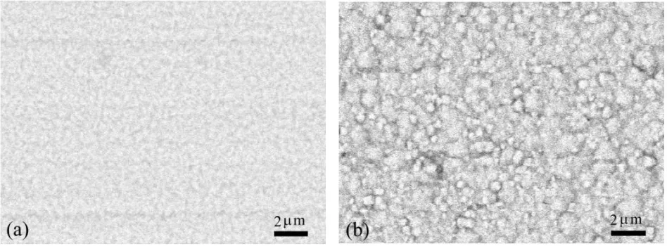
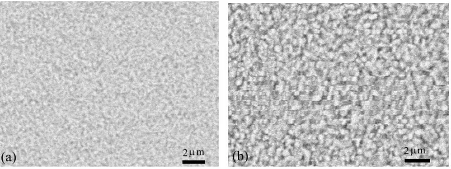
Figure 4. SEM images of Co-Ni films electrodeposited in solution A at 1.1 MHz. The Co-Ni films are (a) 2.5 m and (b) 5.0 m thick.
Figure 4 shows SEM images of the Co-Ni films electrodeposited at 1.1 MHz. The 2.5-m-thick Co-Ni thin film in Fig. 4 (a) shows a smooth, mirror-like surface. In Fig. 4 (b), the surface of the 5.5-m-thick Co-Ni thin film appears as an aggregation of small grains with an edged nodular shape [9,19]. This suggests that the growth mode is a Stranski-Krastanov (SK) mode [20] defined as a roughening transition from a smooth to a rough surface.
3.2. Co-Ni thin films electrodeposited in solution B
Figure 5. Frequency-dependence of the Ni content in a Co-Ni thin film electrodeposited in solution B.
We assume a first order reaction for the formation of a Ni atom and a Co atom from a Ni ion and Co ion. The rate equation [15] is defined by
i=Ni, Co, (4)
where ci is the content of i in the Co-Ni film, [i+2] is the content of the i ion in the solution, and
ki is the rate constant. Using Eq. (4), the Ni content in the Co-Ni thin film becomes
. (5) Taking the average of Eq. (5) over the frequency, we have
(6) and
, (7)
where the overline indicates the average value from 0.3 to 1.2 MHz. The value of kCo/kNi
[image:7.596.50.520.474.687.2]
This indicates that generation of a Co atom is about three times as fast as that of a Ni atom. In other experiments, the deposition rate of Co was larger than that of Ni [13].
[image:8.596.57.540.253.569.2]Figure 6 (a) and (b) show XRD patterns for two Co-Ni thin films: a Co-Ni thin film electrodeposited at 0.6 MHz containing 28 wt% Ni, and a Co-Ni thin film electrodeposited at 1.1 MHz containing 19 wt% Ni. The diffraction peaks are indexed as (002) and (110) planes, which are consistent with those of polycrystalline Co. Hence, the crystal structure is HCP for both Co-Ni thin films. According to the phase diagram for the Co-Ni alloy [12], the phase transition from HCP to FCC occurs at 29 wt% Ni content. Hence, in this experiment, the critical content of Ni for the phase transition is almost consistent with that in the phase diagram.
Figure 6. XRD patterns of Co –Ni films electrodeposited at (a) 0.6 MHz and (b) 1.1 MHz. The Co-Ni thin films are (a) 5.5 m and (b) 5.3 m thick.
Figure 7. SEM images of the Co-Ni films electrodeposited in solution B at 0.6 MHz. The Co-Ni films are (a) 2.8 m and (b) 5.5 m thick.
Figure 7 shows SEM images of the Co-Ni films electrodeposited at 1.1 MHz. The 2.8-m-thick Co-Ni thin film in Fig. 7 (a) shows a smooth, mirror-like surface. In Fig. 7 (b), small grains appear on the surface of the 5.5-m-thick Co-Ni thin film. The surface loses light reflectivity. This suggests that the growth mode of HCP is also the SK mode [21].
4. CONCLUSIONS
The Ni content in the Co-Ni thin films generated by a rectangular pulse current technique in the megahertz range showed the resonant frequency interval independent of the molar ratios between Co and Ni ions in the solution. The resonant frequency interval in Co-Ni electrodeposition was 0.1 MHz lower than that in Ni electrodeposition, which was explained by the energy level transition of electrons to the rotational energy of the linear molecule comprising the Ni ion, Co ion and tartaric ion. The Co-Ni thin films had FCC or HCP structures when the Co-Ni content was higher than 33 wt% or lower than 28 wt%. The growth seemed to be represented by the S-K mode.
References
1. M. Arora, R. Hübner, D. Suess, B. Heinrich, and E. Girt, Phys. Rev. B, 96 (2017) 024401. 2. I. Lytvynenko, C. Deranlot, S. Andrieu, and T. Hauet, J. Appl. Phys., 117 (2015) 053906.
3. N. V. Myung, D.-Y. Park, B.-Y. Yoo, and P. T. A. Sumodjo, J. Magn. Magn. Mater., 265 (2003) 189.
4. C. Liu, F. Su, and J. Liang, Surf. Coat. Technol., 292 (2016) 37.
5. B. Bakhit, A. Akbari, F. Nasirpouri, and M. G. Hosseini, Appl. Surf. Sci., 307 (2014) 351.
6. R. Oriňáková, A. Oriňák, G. Vering, I. Talian, R. M. Smith, and H. F. Arlinghaus, Thin Sold Films, 516 (2008) 3045.
[image:9.596.72.534.77.251.2]
8.A. Bai and C-C. Hu, Electrochim. Acta, 47 (2003) 3447.
9.C. D. Grill, J. P. Kollender, and A. W. Hassel, Phys. Status Solidi A, 212 (2015) 1216. 10.Z. Du and D. Lü, Intermetallics, 13 (2005) 586.
11.T. B. Massalski, Binary Alloy Phase Diagrams 2nd ed., ASM international, Materials Park, Ohio, 1990.
12.A. F. Guillermet, Z. Metallkd., 78 (1987) 639.
13.U. Sarac, M. C. Baykul, and Y. Uguz, J. Supercond. Nov. Magn., 28 (2015) 3105. 14.A. R. Sethuraman, R. J. De Angelis, and P. J. Reucroft, J. Mater. Res., 6 (1991) 749. 15.W. J. Moore, Physical Chemistry 4th ed., Prentice-Hall, New Jersey, 1972.
16.M. Saitou, Int. J. Electrochem. Sci., 11 (2016) 5535.
17.I. Kharmachi, L. Dhouibi, P. Berçot, and M. Rezrazi, J. Mater. Environ. Sci., 7 (2016) 1670. 18.J. I. Langford and A. J. C. Wilson, J. Appl. Crystallogr., 11 (1978) 102.
19.M. Hagarová, D. Jakubéczyová, and J. Cervová, Int. J. Electrochem. Sci., 10 (2015) 9968. 20.A. Baskaran and P. Smereka, J. Apply. Phys., 111 (2012) 044321.
21.M. Saitou, Int. J. Electrochem. Sci., 12 (2017) 2719.