Int. J. Electrochem. Sci., 12 (2017) 3652 – 3661, doi: 10.20964/2017.05.59
International Journal of
ELECTROCHEMICAL
SCIENCE
www.electrochemsci.org
Structure and Performance of Spherical Natural Graphite
Modified by Ag-C Double Coating
Chun-ping Hou1,2,Hao Zhang1, Yong Ma1, Wang-chang Geng1 and Qiu-yu Zhang1,*
1
School of Science, Northwestern Polytechnical University, Xi’an Shaanxi, 710129, P.R. China
2
Ningxia BOLT Technologies Co., Ltd., Yinchuan Ningxia, 750011, P.R. China
*
E-mail: [email protected]
Received: 11 February 2017 / Accepted: 22 March 2017 / Published: 12 April 2017
A liquid-phase method was used to prepare a novel Ag-C double-coated graphite composite anode material. In this method, Ag is deposited on the surface of spherical natural graphite by electroless plating, and the excessive glucose in the solution, which is used as a reductant in the silver mirror reaction, acts as a carbon coating. X-ray diffraction (XRD) and scanning electron microscopy (SEM) have been employed to investigate the microstructure and morphology of the as-prepared samples. Electrochemical tests showed that good low-temperature performance, large rate capability, and good cycle performance have been obtained from the Ag-C double coated graphite composite anode material; thus, it is suitable for power or energy storage batteries. The sample with a content of 0.9 wt% Ag showed the best comprehensive performance with a discharge capacity of 65.2 mAh g-1 when discharged at 0.1 C rate and at -20 °C, which is almost double the discharge capacity of the control sample.
Keywords: Natural graphite; Low-temperature performance; Liquid-phase; Double coating
1. INTRODUCTION
Unfortunately, without further treatment, natural graphite suffers from large potential hysteresis during the charge-discharge cycles and large irreversible reactions during the initial Li-ion intercalation. The above-metioned irreversible reactions are intricate electrochemical reactions involving the electrolyte, a solvent and a graphite electrode, which form a solid electrolyte interface (SEI) that inhibits electronic but not ionic conduction. Once it is completely formed, the SEI prevents further electrochemical irreversible reactions and allows the Li ions to diffuse through and intercalate into the graphite host reversibly.
The formation of metallic Li on the negative graphite electrode in a Li-ion battery, also known as Li plating, leads to severe performance degradation and may also affect battery safety [7]. In addition, graphite anodes undergo severe limitations when used at low temperatures, mainly because of the high polarization that occurs during the Li+ intercalation process. This behaviour can be ascribed to kinetic thresholds, such as the activation polarization that occurs during the charge-transfer processes, or to a reduced Li+ ion diffusivity, as well as to an increase in the ohmic resistance of the active material, the electrolyte and the SEI layer. All of these factors combine to produce an abrupt decrease in the Li intercalation capacity at temperatures below -20 °C. At -30 °C, graphite completely loses its intercalation ability [8-11].
To overcome these shortcomings, some modification methods have been adopted to improve natural graphite anode materials, such as surface modification [12-14], mild oxidation [15], carbon coating [16-18], metal-doping [10, 19], non-metal doping [20-25] and additive adding [26-28], which have been proven to be effective in enhancing rate discharge, low-temperature performance, and cycle performance, as well as reducing irreversible capacity.
The preparation of metal-graphite composites is a practical method used to increase the anode intercalation ability. In this way, a nanosized metallic powder (Ag, Al, Au, Cu, Ni, Sn) has been dispersed in the formulation of the graphite electrodes or a very thin metal coating (Ag, Al, Au, Cu, Ni, Sn, Zn) has been formed on the surface of electrode materials [19, 29, 30]. Among these metals, Ag has a high electroconductivity and has been employed to improve the electronic conductivity of the electrode materials for Li-ion batteries, including in LiNi1/3Co1/3Mn1/3O2 [31], graphite [29], and
silicon [32] electrodes. In addition, carbon coating with a core-shell structure is another effective technique to improve the electrochemical performances of electrode materials such as lithium titanate [3], graphite [17], lithium iron phosphate [33, 34], and lithium manganese phosphate [35, 36].
In this study, a liquid-phase method was adopted to form an Ag-C double coating on the surface of spherical natural graphite (SNG), markedly improving the electrode’s electrochemical characteristics, especially its low-temperature performance.
2. EXPERIMENTAL
2.1. Preparation of spherical natural graphite with Ag-C double coating
dispersed in the prepared silver-ammonia solution. An electroless plating method was used to obtain Ag-coated natural graphite via a silver mirror reaction. The excessive glucose in the solution, which was used as a reductant in the silver mirror reaction, subsequently formed a carbon coating. After drying and the carbonizing treatment, an Ag-C double-coated SNG was obtained. The detailed process was as follows.
AgNO3 solutions of 1.0, 2.0 and 3.0 ml of 1 mol L-1 were each transferred to 100 ml beakers
containing 10 ml of deionized water, and named samples 2#, 3#, and 4#. Sample 1# served as the control and did not undergo the following Ag-C coating treatment. Two drops of a 5 wt% NaOH solution were added drop wise into the above solutions, and the solutions were vibrated to generate a white deposit. Then, a 2 wt% aqueous ammonia solution was added drop wise into each solution until the deposit was completely dissolved. Afterwards a single drop of a 5 wt% NaOH solution was added to each solution.
Twenty-five grams of spherical natural graphite was added to each solution, and the resulting solution was agitated with a magnetic stirrer for 5 minutes. Deionized water was added to each beaker to bring the total solution volume up to 60 ml. Then, 10 ml of a 20 wt% glucose solution was slowly added to each solution and dispersed for 10 minutes in a 50 °C water bath by ultrasonic dispersion. Silver began to appear on the walls of beakers 2#, 3#, and 4#. Thereafter, the four beakers were transferred to an 80 °C water bath and agitated to form an anhydrous paste. Finally, the paste samples were sintered at 350 °C for 4 h to obtain Ag-C double coated spherical natural graphite.
2.2. Characterization
The crystalline form of the synthesized composite materials was characterized by an XRD-7000S diffractometer (Shimadza, Japan) using Cu Ka radiation (λ=0.15423 nm). The surface morphologies of the samples were observed with a scanning electronic microscope (JEOL JSM-6700F, Japan), and the phase compositions of these materials were investigated with an Inca X-act EDS analyser (Oxford Instruments, UK). The particle size distribution of the samples was analysed by Laser Particle Size Analyzers (BT-9000Z, Bettersize, China). The specific surface area and pore diameter were characterized with a NOVA 4000e (Quantachrome, USA).
2.3. Electrochemical studies
(1:1:1, v/v/v) (GuangzhouTinci) as the electrolyte. A LAND batteries testing system (LAND CT2001A, Wuhan, China) was used to perform the galvanostatic charge/discharge tests in the potential range of 0.03-2.0 V (vs.Li+/Li) at a rate of 0.1 C, 0.2 C, 0.5 C and 1C (where 1 C = 372 mA g-1). The conductivities of as-prepared samples were measured with a MCP-PD51 4-pin probe (Mitsubishi Chemical Co., Ltd. Japan).
3. RESULTS AND DISCUSSION
[image:4.596.167.432.225.389.2]3.1. The crystalline forms and morphologies
Figure 1. Schematic process of Ag-C double coating for SNG
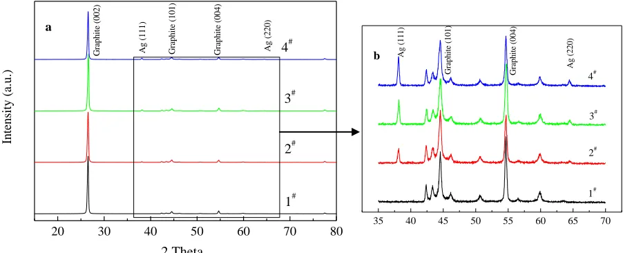
Figure 2. XRD patterns of the as-prepared sample 1# and samples 2#, 3# and 4# (a); Magnification of a single segment of the XRD pattern (b).
As shown in Figure 2 (a), the main diffraction peaks for sample 1# were situated at approximately 26.5º, 44.5º, and 54.6º, which is consistent with the (002), (101) and (004) lattice planes, respectively, and were indexed as the hexagonal structure of hexagonal graphite (PDF Card No.26-1080). No impurity peaks corresponding to Ag-related compounds were observed in the XRD patterns
35 40 45 50 55 60 65 70
b G ra p h it e (0 0 4 ) G ra p h it e (1 0 1 ) A g (2 2 0 ) A g (1 1 1 ) 4# 3# 2# 1#
20 30 40 50 60 70 80
[image:4.596.71.522.457.640.2]
of sample 1#. However, in Figure 2 (b), in addition to graphite, the XRD patterns of samples 2#, 3# and 4# show (111) and (220) lattice planes at approximately 38.1º and 64.4º, respectively, which could be indexed as the space group of Fm-3m cubic Ag (PDF Card No. 04-0783). There was no evidence of other possible, yet undesirable, products. With increasing Ag content, the diffraction peaks became shaper and stronger. This finding is in agreement with a recent study by X. He et al. showing that CH3COOAg is decomposed insitu into Ag NPs on the graphite surface via wetting-thermal
decomposition [29].
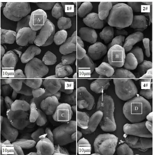
The morphologies of the control sample (1#) and the as-prepared SNG samples (2#, 3# and 4#) by liquid-phase Ag-C double coating are shown in Figure 3. The findings show that a coarse and distinctly lamellar structure was observed on the surface of sample 1#. However, with increasing amounts of Ag and carbon coating, the surfaces of the as-prepared samples look increasingly smooth, and a large number of silvery conglomerations of Ag-particles begin to appear, which was confirmed to be elemental silver by XRD and EDS tests.
Figure 3. SEM images of the control sample (1#) and as-prepared SNG samples (2#, 3# and 4#) by liquid-phase Ag-C double coating.
[image:5.596.139.439.312.615.2][image:6.596.86.508.429.557.2]
particles on the surface of the as-prepared samples but not on the control sample. The EDS dot analyses for dot E, shown as white arrows in Figure 3-4, illustrate that the silvery conglomeration contains 12.72 wt% of carbon and 87.28 wt% of silver. The carbon content occurs because the Ag particles or the conglomerations have been coated by pyrolytic carbon from the glucose.
Table 1. Element weight percentages (wt%) for areas A, B, C, D and Dot E.
Areas or Dot Weight percentages (wt%)
C Ag Total
A 100.00 - 100.00
B 98.27 1.73 100.00
C 97.18 2.82 100.00
D 96.77 3.23 100.00
E 12.72 87.28 100.00
3.2. Physical properties of the control sample and the as-prepared SNG samples
Table 2. Physical properties of the control sample (1#) and the as-prepared SNG samples (2#, 3# and 4#) by liquid-phase Ag-C double coating.
Sample
Particle size distribution (μm) SSA (m2 g-1)
Pore diameter (A)
Conductivity (S cm-1)
D10 D50 D90
1# 9.54 16.51 27.01 5.268 17.031 20.1*10-3
2# 9.76 16.86 27.73 2.330 16.971 23.62*10-3
3# 9.76 16.86 27.81 1.826 15.345 28.41*10-3
4# 9.72 16.76 27.60 1.698 15.337 40.84*10-3
[37]. The data also illustrate that the Ag-C double coating significantly improved the conductivity of the SNG sample. The conductivity of as-prepared samples is also enhanced with increasing Ag addition. Therefore, sample 4# shows the highest conductivity (40.84*10-3 S cm-1). Yang et al revealed that the values of Rct and Di of the as-prepared SS-LFP/C samples varied considerably at different temperatures [38]. As the temperature decreasing, the Rct values of the samples increase while the Di values decrease. The increase of the conductivity of the modified graphite anode material contributes to the improvement of the low-temperature performance for LIBs.
[image:7.596.170.413.229.412.2]3.3. Electrochemical measurements
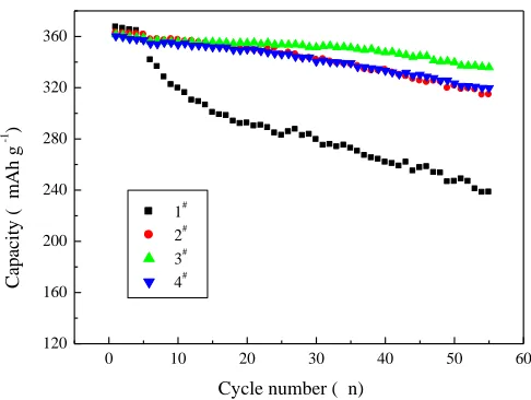
Figure 4. The cycling performances of the control sample (1#) and the as-prepared SNG samples (2#, 3# and 4#) by liquid-phase Ag-C double coating at room temperature and at a rate of 0.1 C.
Figure 4 compares the cycling performances of the control sample (1#) and the as-prepared SNG samples (2#, 3# and 4#) by liquid-phase Ag-C double coating at room temperature and at a rate of 0.1 C. Sample 1# exhibits a poor cycling performance with a capacity retention ratio of only 64.86 % after 55 cycles.
Figure 5. The discharge performances of the control sample (1#) and the as-prepared SNG samples (2#, 3# and 4#) by liquid-phase Ag-C double coating at room temperature and different discharge rates.
0 10 20 30 40 50 60
120 160 200 240 280 320 360 C ap ac it y ( m A h g -1 )
Cycle number ( n)
1# 2# 3# 4# 0 50 100 150 200 250 300 350 400 1.0 0.5 0.2 0.1 D is ch ar g e c ap ac it y ( m A h g -1 )
Discharge Rate (C)
1# 2#
[image:7.596.169.417.535.711.2]
In spite of having almost the same initial capacity, Ag-C coated samples have a fairly good discharge capacity during cycling. Sample 3#, with a content of 0.9 wt% Ag, delivers a discharge capacity of 335.8 mAh g-1 for the fifty-fifth cycle and has a high capacity retention ratio of 92.89 % due to both the formation of an Ag-C double conducting layer and the construction of an Ag-C conductive network on the surface of the SNG through the core-shell structure, as shown in Figure 1 [31]. Therefore, Ag and C double coatings may have a synergistic effect owing to their high electrical conductivities.
In addition to cycling performance, other important factors that should be considered to meet the requirement of EV, HEV or smart grids are the rate capability and the low-temperature characteristics. The discharge performances of the control sample and the as-prepared Ag-C coated samples at different rates are presented in Figure 5. By comparing the untreated SNG with the as-synthesized Ag-C coated SNG, it is shown that the coated electrodes have an excellent rate capability. For example, sample 4# delivers a discharge capacity of 103.2 mAh g-1 at a rate of 1.0 C, which is nearly three times the capacity of sample 1#. The improved rate capability is attributed to the enhanced electro-conductivities of the as-prepared samples that arise from the superior Ag-C combined conductivities. With the introduction of Ag and C, the formation of Ag-C hybrid conductive network can function as a conductive bridge to enhance the electron transfer efficiency among the active materials and reduce the inner resistance of the anode [31]. He’s research also reveals that the intercalation reaction of Li+ with graphite is catalysed by the Ag nanoparticles in the composite [29]. This Ag-C network has been fabricated to take advantage of the possible short and long range electron pathways that exist among the nanoparticles and therefore achieve a significantly improved rate capability.
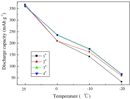
Figure 6. The discharge performances of the control sample (1#) and the as-prepared SNG samples (2#, 3# and 4#) by liquid-phase Ag-Cdouble coating at various temperature and at a rate of 0.1 C.
Figure 6 shows the discharge performances of the control sample (1#) and the as-prepared SNG samples (2#, 3# and 4#) by liquid-phase Ag-C double coating at various temperatures and at a rate of
50 100 150 200 250 300 350
-20 -10
0 25
D
is
ch
ar
g
e
ca
p
ac
it
y
(
m
A
h
g
-1 )
Temperature ( ℃)
[image:8.596.150.397.469.658.2]
0.1 C. In contrast to the pristine SNG sample, the Ag-C double-coated samples show a better low-temperature performance. At -20 °C, samples 3# and 4# (both Ag-C coated) deliver capacities of 65.2 mAh g-1 and 66.4 mAh g-1, respectively, which is nearly two times the capacity of the pristine sample. Thus, it can be inferred that the Ag-C double coating improves the kinetics of Li+ diffusion at low temperature due to the formation of a hybrid conductive network consisting of Ag and C [39, 40]. In addition, Ag and C coating can promote the formation of a compact SEI layer, which can protect the anode material from both the co-intercalation and exfoliation caused by solvent molecules in the electrolyte, and the formation of metallic lithium on the negative graphite electrode in a Li-ion battery.
4. CONCLUSIONS
In this work, Ag and C double coatings were uniformly introduced into the SNG anode to form a hybrid Ag-C conductive network. An abundant number of both short and long range electron pathways are fabricated to provide sufficient contact sites to the as-prepared SNG anode. Accordingly, due to the excellent electronic conductivity achieved, the obtained Ag-C double coated SNG anode exhibits much better cycling performance, rate capability and low-temperature characteristics than the control SNG anode. Furthermore, the Ag-C double coating modified anode shows additional charge transfer advantages due to the synergistic effect of the Ag and C. Sample 3#, with a content of 0.9 wt% Ag, has shown the best comprehensive performance with a discharge capacity of 65.2 mAh g-1 at -20°C and 0.1C rate, which is almost double the discharge capacity of the control sample. Thus, it can be concluded that the introduction of a hybrid Ag-C conductive network is a promising strategy to improve the performance of electrode materials for Li- ion batteries.
ACKNOWLEDGEMENTS
This work was supported by the Science and Technology Innovation Leader Program of Ningxia Hui Autonomous Region, the Key Research Project of Ningxia Hui Autonomous Region (2016), and the Key Research Project of Beifang Univesity of Nationality (grant 2015KJ30).
References
1. J. M. Tarascon, M. Armand, Nature, 414 (2001) 359. 2. J. B. Goodenough, Y. Kim, Chem. Mater., 22 (2010) 587.
3. L. Shen, H. Li, E. Uchaker, X. Zhang and G. Cao, Nano Lett., 12 (2012) 1.
4. W. Zhu, D. Liu, J. Trottier, C. Gagnon, J. Howe, A. Mauger, C. M. Julien and K. Zaghib, J. Power Sources, 298 (2015) 341.
5. K. Amine, I. Belharouak, Z. Chen, T. Tran, H. Yumoto, N. Ota, S. T. Myung and Y. K. Sun, Adv. Mater., 22 (2010) 3052.
6. T. S. Ong, H. Yang, Carbon, 38 (2000) 2077.
7. M. Petzl, M. Kasper and M. A. Danzer, J. Power Sources, 275 (2015) 799.
8. M. Yamagata, Y. Matsui, T. Sugimoto, M. Kikuta, T. Higashizaki, M. Kono and M. Ishikawa, J. Power Sources, 227 (2013) 60.
9. G. Park, N. Gunawardhana, H. Nakamura, Y. S. Lee and M. Yoshio, J. Power Sources, 199 (2012) 293.
11.E. Markevich, G. Salitra and D. Aurbach, J. Electrochem. Soc., 163 (2016) A2407.
12.H. L. Zhu, P. P. Lu, Z. Y. Chen, J. Li, F. Chen, B. L. Du and Y. Q. Lai, Chin. J. Nonferrous Met., 24 (2014) 779.
13.N. C. Gallego, C. I. Contescu, H. M. Meyer, J. Y. Howe, R. A. Meisner, E. A. Payzant, M. J. Lance, S. Y. Yoon, M. Denlinger and D. L. Wood, Carbon, 72 (2014) 393.
14.T. Xing, L. H. Li, L. Hou, X. Hu, S. Zhou, R. Peter, M. Petravic and Y. Chen, Carbon, 57 (2013) 515.
15.S. Y. Lee, H. K. Shin, M. Park, K. Y. Rhee and S. J. Park, Carbon, 68 (2014) 67. 16.F. S. Li, Y. S. Wu, J. Chou, M. Winter and N. L. Wu, Adv. Mater., (2014) 130.
17.H.L. Zhang, S.H. Liu, F. Li, S. Bai, C. Liu, J. Tan and H. M. Cheng, Carbon, 44 (2006) 2212. 18.M. Yoshio, H. Wang and K. Fukuda, Angew. Chem. Int. Edit., 42 (2003) 4203.
19.C. Ma, Y. Zhao, J. Li, Y. Song, J. Shi, Q. Guo and L. Liu, Carbon, 64 (2013) 553.
20.C. Ma, C. Ma, J. Wang, H. Wang, J. Shi, Y. Song, Q. Guo and L. Liu, Carbon, 72 (2014) 38. 21.K. Saravanan, N. Kalaiselvi, Carbon, 81 (2015) 43.
22.I. P. Asanov, A. V. Okotrub, A. V. Gusel’nikov, I. V. Yushina, D. V. Vyalikh and L. G. Bulusheva, Carbon, 82 (2015) 446.
23.M. Dubois, K. Guérin, Y. Ahmad, N. Batisse, M. Mar, L. Frezet, W. Hourani, J. L. Bubendorff, J. Parmentier, S. Hajjar-Garreau and L. Simon, Carbon, 77 (2014) 688.
24.H. Wang, Q. Guo, J. Yang, Y. Zhao, X. Wang, Z. Tao, Z. Liu, Z. Feng and L. Liu, Carbon, 52 (2013) 10.
25.M. S. Park, J. Lee, J. W. Lee, K. Jae, Y. N. Jo, S. G. Woo and Y. J. Kim, Carbon, 62 (2013) 278. 26.B. Yang, H. Zhang, L. Yu, W. Fan and D. Huang, Electrochim. Acta, 221 (2016) 107.
27.W. Lu, S. Xiong, K. Xie, Y. Pan and C. Zheng, Ionics, (2016) 2095.
28.S. Jurng, S. Park, T. Yoon, H. S. Kim, H. Jeong, J. H. Ryu, J. Kim and S. M. Oh, J. Electrochem. Soc., 163 (2016) A1798.
29.X. He, D. Hubble, R. Calzada, A. Ashtamkar, D. Bhatia, S. Cartagena, P. Mukherjee and H. Liang, J. Power Sources, 275 (2015) 688.
30.Y. Yan, L. Ben, Y. Zhan and X. Huang, Electrochim. Acta, 187 (2016) 186. 31.F. Zhou, K. Qiu, G. Peng and L. Xia, Electrochim. Acta, 151 (2015) 16.
32.Y. Yu, L. Gu, C. Zhu, S. Tsukimoto, P. A. V. Aken and J. Maier, Adv. Mater., 22 (2010) 2247. 33.J. K. Kim, CrystEngComm, 16 (2014) 2818.
34.J. Liu, G. Yang, X. Zhang, J. Wang and R. Wang, J. Power Sources, 197 (2012) 253.
35.Y. P. Huang, T. Tao, Z. Chen, W. Han, Y. Wu, C. Kuang, S. Zhou and Y. Chen, J. Mater. Chem. A, 2 (2014) 18831.
36.B. Ding, P. Xiao, G. Ji, L. Lu and J. Y. Lee, ACS Appl. Mater. Interfaces, (2013) 12120.
37.A. Senyshyn, M. J. Mühlbauer, O. Dolotko and H. Ehrenberg, J. Power Sources, 282 (2015) 235. 38.C. C. Yang, J. H. Jang and J. R. Jiang, Applied Energy, 162 (2016) 1419.
39.L. Co, O. Mn, J. Mater. Sci., 49 (2014) 7707.
40.S. Bae, H. D. Song, I. Nam, G. P. Kim, J. M. Lee and J. Yi, Chem. Eng. Sci., 118 (2014) 74.