Int. J. Electrochem. Sci., 14 (2019) 5154 – 5160, doi: 10.20964/2019.06.59
International Journal of
ELECTROCHEMICAL
SCIENCE
www.electrochemsci.orgShort Communication
Carpet-like TiO
2Nanofiber Interlayer as Advanced Absorber
for High Performance Li-S batteries
Pengfei Huang1, Yinwei Wang1, 2 *
1 School of Mechanical Engineering, Xijing University, Xi’an 710123, China
2 Intelligent Manufacturing Research and Development Center, Xijing University, Xi’an 710123,China *E-mail: yinweiwang@aliyun.com
Received: 6 Febraury 2019 / Accepted: 1 April 2019 / Published: 10 May 2019
It is evident that the polysulfide will take place the shuttle effect between the cathode and anode in the Li-S battery. This is proved by many experiment studies in the past decades. Therefore, the most efficient method for improving the electrochemical performance of Li-S battery is inhibiting this shuttle effect. Based on this idea, we design a free-standing carpet-like TiO2 nanofiber skeleton interlayer in the Li-S battery. This advanced interlayer could stem the transfer of soluble polysulfide, which shuttle between cathode and anode. Besides, the nanofiber structure in the carpet-like TiO2 nanofiber skeleton interlayer provides channels for the rapid transport of lithium-ions. Considering all these advantages, the as-prepared TiO2 interlayer shows perfect electrochemical performance for the Li-S batteries.
Keywords: Shuttle Effect, Electric Vehicles, New Energy, Li-S Battery, Electrochemical Performance.
1. INTRODUCTION
Lithium-sulfur batteries (Li-S) have become the new energy storage in the recent years due to their various advantages, such as high specific capacity, high energy density and power density [1, 2, 3]. Clearly, the most promising candidate for the automobile is the Li-S battery [4, 5]. The electronic automobile needs the energy storage systems which have high energy density. Therefore, many researchers and companies are devoted into the studies for the high-performance Li-S batteries [6, 7]. So far, the main works about Li-S battery focused on the cathode materials, anode modification and electrolyte [8-11]. There are few reports about the employment of functional interlayers in the Li-S battery system [12, 13].
Unfortunately, these two indexes for Li-S batteries are so bad that they cannot satisfy the requirements for new electronic automobile. The main reason for the bad performance is the shuttle effect of polysulfide, which is produced during the electrochemical processes [16, 17]. Consequently, the most efficient method for improving the electrochemical performance of Li-S battery is inhibiting this shuttle effect [18]. Many studies develop perfect cathode materials, while they ignore the design of advanced functional interlayer between the cathode side and separator side [19]. Only by this strategy, the radical problem in the Li-S batteries could be solved absolutely.
Based on this idea, in this study, we design a free-standing carpet-like TiO2 nanofiber skeleton interlayer in the Li-S battery. This advanced interlayer could stem the transfer of soluble polysulfide, which shuttle between cathode and anode. Besides, the nanofiber structure in the carpet-like TiO2 nanofiber skeleton interlayer provides channels for the rapid transport of lithium-ions. Considering all these advantages, the as-prepared TiO2 interlayer shows perfect electrochemical performance for the Li-S batteries.
2. EXPERIMENTAL
2.1. Materials Synthesis
1.2 ml Titanium isopropoxide (TIP) and 150 ml ethanol were mixed while stirring for 4 hours. Then, 1.6 ml NH3H2O was added step by step into the above solution. Until the reaction was completed, the precipitate was collected by centrifugation and washed three times using water and ethanol, and dried in a vacuum oven at 120 ° C for 12 h. Finally, the carpet-like TiO2 powder was obtained. Then, the carpet-like TiO2 (CP-TO) powder was added into the PTFE emulsion with a mass ratio of 2:1. The mixture was added into ethanol to form solution and dried at 80℃ to volatilize the ethanol. The as-prepared solid was pressed into a film by a twin roller and dried at 70 ℃. Finally, it was punched into a carpet-like TiO2 (CP-TO) interlayer with a diameter of 16 mm.
2.2. Materials Characterization
The structure and morphology of the samples were characterized by X-ray diffraction (Bruker D8 advance diffractometer with Cu-Kα radiation, 40kV and 200mA), scanning electron microscopy (SEM) (SU-70) and X-ray photoelectron spectroscopy (XPS) (ESCALAB 250Xi).
2.3. Electrochemical Tests
(DME) (volume ratio 1:1) in a glove-box filled with argon. The charge/discharge tests were applied on landian (LADCT 2001A) instruments with a voltage domain of 1.5 V~3.0 V. Electrochemical impedance spectroscopy (EIS) was measured on workstation (CHI660E) with a testing condition that alternating current voltage of 10 mV in the frequency range from 100 kHz to 0.01 Hz.
3. RESULTS AND DISCUSSION
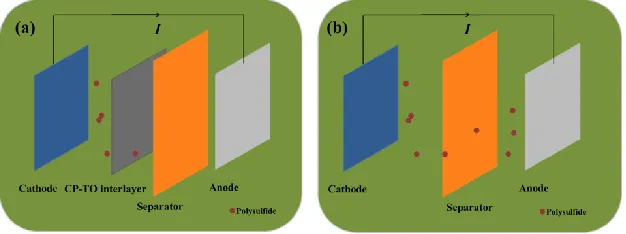
Figure 1 shows the preparation of Li-S battery used CP-TO interlayer. As shown in Figure 1c, the as-prepared CP-TO plasticine was rolled into flake and finally punched into circle-like interlayer. Then, this circle-like CP-TO interlayer was placed between the cathode and separator in the coin Li-S battery. Figure 1a and b compare the effect of the CP-TO interlayer in the Li-S battery. It can be concluded that the Li-S battery by using CP-TO interlayer could inhibit the shuttle effect of polysulfide. It can make the polysulfide stay at the cathode side. While the Li-S battery without interlayer, the severe shuttle effect of polysulfide exist in the whole system. This figure can explain the significant effect of CP-TO interlayer theoretically.
Figure 1. The comparison of Li–S batteries by using (a) CP-TO interlayer and (b) without CP-TO interlayer.
Figure 2. (a) SEM image of Carpet-like TiO2 Nanofiber Skeleton. (b) The Cross-SEM image of the CP-TO interlayer.
[image:3.596.143.456.361.478.2] [image:3.596.160.441.537.652.2]
of 2 µm. And the surface is smooth. The cross SEM image of the CP-TO interlayer (Figure 2b) indicates that the CP-TO interlayer is loose, which is good for the rapid transport of lithium-ions [20]. Besides, the loose structure could store the soluble polysulfide which is generated during the discharging charging process at various current densities.
The XRD pattern of the CP-TO is displayed in Figure 3a. The diffraction peaks of the CP-TO can be well matched with the anatase structure (JCPDS card No. 21-1272) [21]. This demonstrates that the CP-TO have been prepared successfully. XPS is also conducted for judging the synthesis of the sample. As shown in Figure 3b, from the Ti 2p spectra, the main peak at 459.1 eV could be clearly observed [22]. This main peak can be ascribed to the Ti-O bond. These results indicate that the chemical bond exists in the CP-TO interlayer, which is beneficial for the improvement of the Li-S battery.
Figure 3. (a) XRD pattern of CP-TO, (b) XPS of Ti 2p for the CP-TO.
The electrochemical performances are shown in Figure 4. Figure 4a is the discharge/charge curves of the Li-S battery by using CP-TO interlayer at the current densities of 0.1 C, 0.2 C, 0.5 C, 1 C and 2 C, respectively. It can be observed the specific capacity of CP-TO interlayer is 1106 mAh g-1 at 0.1 C. With the development of the current density, the capacity value varies slowly. This result demonstrates that the CP-TO interlayer could release sufficient capacity at the high current density. On the other hand, two voltage platforms are seen in the discharge profiles at 2.3 V and 2.1 V, respectively. This is the typical character of the discharge charge curves for the Li-S batteries [23].
Figure 4b shows the rate capability of the Li-S battery by using CP-TO interlayer and without CP-TO interlayer. The Li-S battery by using CP-TO interlayer could display capacity value of 701 mAh g-1 at the current density of 2 C. Moreover, the capacity value changes little when the current density is improved from 0.1 C to 2C. However, for the Li-S battery without CP-TO interlayer, the capacity fades rapidly with the enhancement of the current densities. This result demonstrates that the Li-S battery by using CP-TO interlayer could endure various current densities even at the very high current density. Therefore, the CP-TO interlayer could provide sufficient rate performance for the Lithium-sulfur battery [24, 25].
[image:4.596.130.470.275.411.2][image:5.596.128.465.170.405.2]
However, the capacity of Li-S battery without CP-TO interlayer fades rapidly with the discharge charge cycles. All of this improvement for the electrochemical performances can be ascribed to the carpet-like structure of the CP-TO interlayer, which could stem the transfer of soluble polysulfide and provide channels for the rapid transport of lithium-ions at the same time [26].
Figure 4. (a) Discharge-charge curves of Li-S battery by using CP-TO interlayer. (b) Rate capability, (c) Cycle stability of Li-S battery by using CP-TO interlayer and without CP-TO interlayer.
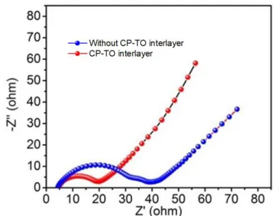
EIS measurement is applied for investigating the electronic conductivity of the Li-S battery. As shown in Figure 5, the EIS of the Li-S battery by using CP-TO interlayer and without CP-TO interlayer is similar. They are all consisted of semicircle in the high frequency and slant in the low frequency. The semicircle represents the electronic conductivity on the surface of the cathode electrode. The slant represents the transport of Li+ in the electrolyte [27]. Clearly, the smaller semicircle of the Li-S battery by using CP-TO interlayer indicates that more strong electronic conductivity than the battery without CP-TO interlayer. Besides, the Li-S battery by using CP-TO interlayer has much higher transmission coefficient of Li+, which could be observed from the slant in the low frequency. This result is accorded with the CP-TO structure. The fibers in the CP-TO structure could provide channels for the rapid transport of lithium-ions.
Figure 5. EIS of Li-S battery by using CP-TO interlayer and without CP-TO interlayer.
Table 1. Performance of CP-TO interlayer comparing with the reported interlayers for Li-S batteries.
Interlayers Initial Capacity Current Cycle Stability ref MWCNTs-OH 1100 (mAh/g) 0.5 C 601 (100 cycles) 28
MS-G 840 (mAh/g) 0.5C 620 (200 cycles) 29
P0.4/NG-1000 920 (mAh/g) 0.5 C 591 (200 cycles) 30 CP-TO 1052 (mAh/g) 0.5 C 906 (200 cycles) This work
4. CONCLUSIONS
In summary, we design a free-standing carpet-like TiO2 nanofiber skeleton interlayer in the Li-S battery. This advanced interlayer could stem the transfer of soluble polysulfide, which shuttle between cathode and anode. Besides, the nanofiber structure in the carpet-like TiO2 nanofiber skeleton interlayer provides channels for the rapid transport of lithium-ions. The as-prepared CP-TO interlayer shows the initial specific capacity of 1052 mAh g-1. Even after 200 cycles at 0.5 C, the capacity value could stay at about 906 mAh g-1.
ACKNOWLEDGEMENT
This research is financially supported by National Key S&T Special Projects (2017ZX04011010).
References
1. L. L. Fan, M. Li, X. F. Li, W. Xiao, Z. W. Chen and J. Lu, Joule, 3 (2019) 361.
2. X. L. Lu, Q. F. Zhang, J. Wang, S. H. Chen, J. M. Ge, Z. M. Liu, L. L. Wang, D. C. Gong and B. G. Lu, Chem. Eng. J., 358 (2019) 955.
3. J. Ni, L. M. Jin, M. Z. Xue, J. S. Zheng, J. P. Zheng and C. M. Zhang, Electrochim. Acta, 296 (2019) 39.
[image:6.596.197.398.74.232.2]
5. Q. S. Wang, L. H. Jiang, Y. Yu and J. H. Sun, Nano Energ., 55 (2019) 93.
6. Y. Liu, A. K. Haridas, Y. Lee, K. K. Cho and J. H. Ahn, Appl. Surf. Sci., 472 (2019) 135.
7. L. Y. Du, Q. Wu, L. J. Yang, X. Wang, R. C. Che, Z. Y. Lyu, W. Chen, X. Z. Wang and Z. Hu, Nano Energ., 57 (2019) 34.
8. R. L. Yang, H. W. Du, Z. Q. Lin, L. L. Yang, H. Zhu, Z. K. Tang and X. C. Gui, Carbon, 141 (2019) 258.
9. H. J. Zhao, N. P. Deng, J. Yan, W. M. Kang, J. G. Ju, Y. L. Ruan, Q. X. Li and B. W. Cheng, Chem. Eng. J., 347 (2018) 343.
10.L. Shan, C. Y. Rong, Y. Jing, R. F. Xia, W. Jun, S. B. Du, Y. Xin, G. J. Kuo and Y. J. Ming, J. Alloy Compd., 779 (2019) 412.
11.Q. F. Peng, F. Yu, W. K. Wang, A. B. Wang, F. Wang and Y. Q. Huang, Electrochim. Acta, 299 (2019) 749.
12.H. P. Li, L. C. Sun, Y. Zhao, T. Z. Tan Y. G. Zhang, Appl. Surf. Sci., 466 (2019) 309. 13.Q. Zhang, H. L. Wan, G. Z. Liu, Z. G. Ding and X. Y. Yao, Nano Energ., 57 (2019) 771. 14.P. H. Ji, B. Shang, Q. M. Peng, X. B. Hu and J. W. Wei, J. Power Sources, 400 (2018) 572. 15.W. Y. Li, Y. Pang, T. C. Zhu, Y. G. Wang and Y. Y. Xia, Solid State Ionics, 318 (2018) 82.
16.D. D. Cheng, P. P. Wu, J. W. Wang, X. W. Tang, T. An, H. Zhou and T. X. Fan, Carbon, 143 (2019) 869.
17.H. G. Feng, M. Zhao, J. W. Kang, Q. M. Su, G. H. Du and B. S. Xu, Mater. Res. Bull., 113 (2019) 70.
18.Z. W. Ding, D. L. Zhao, R. R. Yao, C. Li, X. W. Cheng and T. Hu, Int. J. Hydrogen Energ., 43 (2018) 10502.
19.A. Chen, W. F. Liu, H. Hu, T. Chen, B. L. Ling and K. Y. Liu, J. Power Sources, 400 (2018) 23. 20.S. Xu, Y. Y. Cheng, L. Zhang, K. H. Zhang, F. Huo, X. P. Zhang and S. J. Zhang, Nano Energ., 51
(2018) 113.
21.H. Zhang, P. J. Zuo, J. F. Hua, Y. L. Ma, C. Y. Du, X. Q. Cheng Y. Z. Gao and G. P. Yin, Electrochim. Acta, 238 (2017) 257.
22.L. Q. Lu, J. M. Hosson, Y. T. Pei, Carbon, 144 (2019) 713.
23.S. Q. Li, G. F. Ren, M. F. Hoque, Z. H. Dong and Z. Y. Fan, Appl. Surf. Sci., 396 (2017) 637. 24.Y. W. Zhu, J. Li and J. Liu, J. Power Sources, 351 (2017) 17.
25.Z. H. Wang, W. D. Wang, W. Sun and K. N. Sun, Electrochim. Acta, 252 (2017) 127. 26.D. K. Lee, C. W. Ahn and H. J. Jeon, J. Power Sources, 360 (2017) 559.
27.Z. Li, B. Y. Guan, J. T. Zhang and X. W. Lou, Joule, 1 (2017) 576.
28.Y. P. Huang, X. G. Sun, J. Wang, X. Li, W. Chen, C. C. Wei, H. Hu and G. D. Liang, J. Alloy Compd., 776 (2019) 187.
29.P. Q. Guo, D. Q. Liu, Z. J. Liu, X. N. Shang, Q. Liu and D. Y. He, Electrochim. Acta, 256 (2017) 28.