Recreating blood-brain barrier physiology and structure
on chip: A novel neurovascular microfluidic bioreactor
Jacquelyn A.Brown,1,2VirginiaPensabene,1Dmitry A.Markov,1,2 VanessaAllwardt,3M. DianaNeely,4MingjianShi,5Clayton M.Britt,3 Orlando S.Hoilett,3QingYang,3Bryson M.Brewer,6Philip C.Samson,1,2 Lisa J.McCawley,1,2,7James M.May,8Donna J.Webb,5DeyuLi,6 Aaron B.Bowman,4Ronald S.Reiserer,2,3and John P.Wikswo1,2,3,8 1
Department of Biomedical Engineering, Vanderbilt University, Nashville, Tennessee 37235, USA
2
Vanderbilt Institute for Integrative Biosystems Research and Education, Vanderbilt University, Nashville, Tennessee 37235, USA
3
Department of Physics and Astronomy, Vanderbilt University, Nashville, Tennessee 37235, USA
4
Department of Neurology, Vanderbilt Kennedy Center, Vanderbilt Brain Institute, Vanderbilt Center in Molecular Toxicology, Vanderbilt University, Nashville, Tennessee 37232, USA
5
Department of Biological Sciences, Vanderbilt University, Nashville, Tennessee 37235, USA
6
Department of Mechanical Engineering, Vanderbilt University, Nashville, Tennessee 37235, USA
7
Department of Cancer Biology, Vanderbilt University, Nashville, Tennessee 37232, USA
8
Department of Molecular Physiology and Biophysics, Vanderbilt University, Nashville, Tennessee 37235, USA
(Received 24 August 2015; accepted 10 October 2015; published online 26 October 2015)
The blood-brain barrier (BBB) is a critical structure that serves as the gatekeeper between the central nervous system and the rest of the body. It is the responsibility of the BBB to facilitate the entry of required nutrients into the brain and to exclude potentially harmful compounds; however, this complex structure has remained difficult to model faithfully in vitro. Accurate in vitro models are necessary for understanding how the BBB forms and functions, as well as for evaluating drug and toxin penetration across the barrier. Many previous models have failed to sup-port all the cell types involved in the BBB formation and/or lacked the flow-created shear forces needed for mature tight junction formation. To address these issues and to help establish a more faithful in vitromodel of the BBB, we have designed and fabricated a microfluidic device that is comprised of both a vascular chamber and a brain chamber separated by a porous membrane. This design allows for cell-to-cell communication between endothelial cells, astrocytes, and pericytes and independent perfusion of both compartments separated by the membrane. This NeuroVascular Unit (NVU) represents approximately one-millionth of the human brain, and hence, has sufficient cell mass to support a breadth of analytical meas-urements. The NVU has been validated with both fluorescein isothiocyanate (FITC)-dextran diffusion and transendothelial electrical resistance. The NVU has enabled in vitro modeling of the BBB using all human cell types and sampling effluent from both sides of the barrier.VC 2015 Author(s). All article content, except
where otherwise noted, is licensed under a Creative Commons Attribution 3.0 Unported License. [http://dx.doi.org/10.1063/1.4934713]
I. INTRODUCTION
The blood-brain barrier (BBB) is a critical structure acting as the gatekeeper between the cen-tral nervous system (CNS) and the rest of the body. Not only does this unique barrier regulate
traffic of small molecules, hormones, and nutrients between the body and the brain but it is also the principal means of regulating drug and toxin access into the brain. Because of these features, the ability to model the BBB is essential to testing the delivery and safety of drugs designed to act in the CNS.
The BBB is also a complex structure comprised of multiple cell types, of which endothelial cells have received the most attention. Tight junctions between endothelial cells form a physical link and prevent the passage of molecules from the blood directly into the brain. It has been shown that both cell-to-cell interactions and diffusible cues from the CNS, primarily originating from pericytes and astrocytes, are necessary for cell polarity and the proper formation of tight junctions.1,2 In addition to multiple cell types, true formation of a BBB requires shear forces experienced by endothelial cells from blood circulation, as well as the differential serum con-centration across the BBB.3,4 Thus, recapitulation of this complicated and dynamic barrier of the BBB requires innovation for high fidelity modeling.
Current animal models, while informative, are expensive and have been shown to lack con-sistent predictive value for humans.5–7Recent research has shown that microvascular cells have species-specific properties that may account for these differences between the human BBB and those of other mammalian species. Current computer models of the BBB are excellent for high-throughput studies and limit cost, but they are only useful for predicting basic permeability based on drug structure—they cannot provide information as to the efficacy of the drug in question or whether the drug itself may influence BBB permeability.8,9Traditional transwell cell culture mod-els have the advantage of being able to use actual human cells with relatively high throughput, but it has been demonstrated that many of the cell types used in these experiments do not main-tain their terminally differentiated state under these culture conditions, causing perturbations and abnormalities within the BBB.6,10–13 Three-dimensional dynamic models overcome the differen-tiation issues seen within transwells, but do not faithfully recapitulate the lumen and sub-lumen spaces which allow for endothelial cell specialization14–18 and polarization.5,19,20 In addition, these static models lack continually refreshed media.14,21–23All of the current models add to our understanding of the BBB formation and function; however, each still leaves room for improve-ment to better represent this complex, multi-dimensional, multi-cellular brain structure.
The organ-on-chip community is expending significant effort on the development of advanced, tissue-engineered microphysiological systems, typically using microfluidics.24–27Planar microfluidic BBB models are excellent for examining the BBB in cross-section, particularly to observe leukocyte extravasation, but lack the cell number to support in-depth secretome characterization.28–31 To address the limitations of the classic BBB models and extend the capabilities of planar microfluidic ones, we have developed a self-contained microfluidic bioreactor that recreates thein vivo-like con-ditions of the BBB in vitro. Our BBB organ-on-a-chip system, termed the NeuroVascular Unit (NVU), supports growth and development of primary cell-derived human neurons, astrocytes, pericytes, and microvascular endothelial cells, all of which are involved in the proper formation of the BBB. The NVU not only allows these cells to differentiate and survive but also recreates such important microenvironmental conditions as cell-to-fluid volume ratios, spatial gradients, and proper fluid flows with appropriate shear stresses. We believe that our organ-on-a-chip NVU sys-tem will enable bridging the gap between animal and human models of the BBB and help in understanding how various assaults and manipulations can perturb the function of the BBB.
II. MATERIALS AND METHODS
A. NVU design
Our NVU (Figure 1(a)) is designed to be approximately one-millionth the size of an adult human brain.32 The NVU is made up of three polydimethylsiloxane (PDMS) layers (Figure
perfusion streams, one for the vascular media supply to the endothelial cells in layer 1 (Figure
1(c), on bottom in red), with an inlet and outlet port, and another for the brain media supply to layers 2 and 3 (in blue, Figure 1(c)), with four ports, so that one diagonal pair can be used for collagen and cell loading and the other for subsequent perfusion of the brain compartment. While not in use, these ports are closed with knotted tubing. The design of layer 3 was chosen to facilitate even and uniform loading of collagen gel containing cells. The volumes of the vas-cular and brain chambers are 2.91ll and 17.5ll, respectively. The two chambers share a com-mon outline, eliminating problems that might arise in crossed-channel bioreactors wherein only a portion of the two chambers overlap, creating larger populations of cells that do not share im-portant signals.28,30 Because we need to grow cells on each side of the membrane, it is neces-sary to perfuse the NVU device first with the vascular side of the membrane facing up to seed the endothelial cells. Once the cells adhere to the membrane, the device can be turned over so that the vascular side faces down, allowing the seeding of astrocytes and pericytes to the other side of the membrane. It is always a challenge to invert transwell inserts for this purpose, but for the NVU we designed a flippable backpack that maintains the feed and collection vials in an upright position regardless of the orientation of the NVU device (Supplementary Figures
[image:3.612.155.456.96.433.2]1(a) and 1(b)).69 This backpack enables culture of the NVU in either of its orientations while still maintaining a standard 6-well footprint for ease of imaging (Figure1(d)).
B. NVU fabrication and assembly
We used standard soft-lithographic replica molding to create the three layers of PDMS that comprise the NVU.33 The vascular layer and brain perfusion (or “H” layer, given its overall shape) (Figure 1(b), layers 1 and 3, respectively) were produced by pouring PDMS onto a mold created photolithographically with SU-8 2100 photoresist (MicroChem, Newton, MA, USA) on Si wafers. The channel height was 100lm. The final thicknesses of the cured PDMS for the vascular layer and “H” layer were 1 mm and 3 mm, respectively. The brain compartment (Figure 1(b), layer 2) was fabricated by curing PDMS sandwiched between two large polycar-bonate plates separated by 500lm spacers with a block that defined the layer 2 brain chamber. This resulted in a PDMS membrane of uniform thickness and a well-defined brain culture chamber that is 4.75 mm long6.2 mm wide0.5 mm deep. For all steps, we used a standard 10:1 ratio mixture of PDMS (Dow Corning).
The following procedure was used to assemble the NVU. After the PDMS was poured onto the Si/SU-8 molds, it was allowed to cure overnight at 65C. All layers were then removed from their molds, trimmed to size, washed with isopropanol, and dried with nitrogen gas. We used a Harrick model PDC-001 plasma oven to activate the PDMS surface and irreversibly bond layers to each other and the glass slide. First, the vascular layer 1 was plasma-treated and bonded to a 50 mm 75 mm microscope glass slide with the chamber facing upward. Next, four access ports in layer 3 were punched for 1.5 mm OD Tygon tubing, and both layers 2 and 3 were bonded to each other. Then the polycarbonate filter membrane (Sigma CAT #111106) with 0.2lm pores was bonded to layers 2 and 3 with 5% solution of 3-aminopropyltriethoxysilane (APTES, 99% Cat #440140, Sigma-Aldrich, St. Louis, MO, USA) using the protocol described in Ref. 34. Once the filter membrane was bonded, two additional ports were punched through layers 2 and 3 to create access to load and perfuse the endothelial cells in layer 1. Finally, both layer 1, attached to a glass slide, and combined layers 2 and 3 with the APTES-treated filter membrane were exposed to oxygen plasma again and bonded together, creating a sealed NVU device. Immediately following assembly, while the surfaces were still hydrophilic, both compart-ments of the NVU were loaded with deionized (DI) water. Care was taken not to trap any air bubbles within the rectangular brain compartment. If any did get trapped, the devices were placed under house vacuum until the bubbles were dissipated through the PDMS walls. All NVU bioreactors were gamma sterilized and stored under water until use.
C. Cell loading and culture in microfluidic devices
Primary human brain-derived microvascular endothelial cells (hBMVEC) from Applied Cell Biology (Kirkland, WA, USA) were maintained in endothelial basal medium (EBM)-2 (Lonza, Basel, Switzerland) containing 5% fetal bovine serum (FBS) and their growth bullet kit; however, penicillin streptomycin 1 was substituted for the gentamicin to prevent neuronal toxicity. Pericytes and astrocytes from ScienCell (Carlsbad, CA, USA) and ATCC (Manassas, VA, USA), respectively, both primary cells, were maintained in Dulbecco’s modified Eagle’s medium (DMEM) F-12%þ10% FBS. All cells, except human neurons (described next), were maintained in T-25 flasks under standard culture procedure35until collected for seeding into the NVU.36–38
Human induced pluripotent stem cells (hiPSCs) from de-identified normal subjects were generated and maintained as previously described.39,40 From these, human cortical glutamater-gic neurons were differentiated in multi-well plates coated with Matrigel for 80–90 days by an 11-day dual-SMAD inhibition protocol to generate early PAX6-positive forebrain neuroprogeni-tors, followed by a cortical glutamatergic neuron induction protocol, as previously described. Immediately prior to seeding into the NVU, the resulting human glutamatergic neurons were harvested using Accutase (Innovative Cell Technologies, Inc., San Diego, CA, USA).
endothelial cells to the porous membrane. On Day 1, still inverted, the NVU was connected to a constant 2ll/min flow of EBM-2 media delivered by either a syringe or peristaltic pump and maintained this way until Day 12. On Day 12, the device was placed right-side up, and astrocytes at 2106cells/ml and pericytes at 1106cells/ml were mixed and loaded into the brain cham-ber and maintained under flow for two days. On Day 14, hiPSC-derived neurons were suspended within a collagen I matrix (Invitrogen) at 1 106cells/ml, loaded into the brain chamber, and allowed to solidify for 2 h before flow was restarted at 2ll/min. This complete device was cul-tured for 3 days in the presence of Rho-associated coiled-coil kinase (ROCK) inhibitor (10lM, Tocris) Y-27632 (Sigma-Aldrich, St. Louis, MO, USA) on the brain side to help the neurons sur-vive. Y-27632 (inhibitor for p160-ROCK) markedly diminishes dissociation-induced anoikis (detachment-induced apoptosis) of dissociated single hiPSCs.41 It has been shown that ROCK in-hibitor also increases the survival rate during thawing and re-plating of dissociated hiPSC-derived neural precursors and mature neurons and supports regrowth of neurites after injury.42–45The pro-cess of loading the neurons into the NVU requires their removal from the original culture dish in which they were differentiated and their dissociation into single cells. Thus, ROCK-inhibitor Y-27632 was added to the medium for the first 3 days after seeding the neurons into the NVU to boost their survival. Once the ROCK inhibitor has been removed, the blood-brain barrier within the NVU is considered mature because (1) tight junctions have formed, (2) all barrier cells are at confluence, and (3) the neurons no longer need ROCK inhibition for survival. Finally, all cells were perfused with EBM-2 media, and the device was ready for testing.
D. Establishing a cellular blood-brain barrier
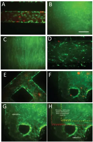
To truly recapitulate the complexity of the BBB, we felt it imperative that its three major cell types be present (endothelial cells, astrocytes, and pericytes), as well as neurons to evaluate neuronal response to changes in BBB permeability. To this end we lined the vascular chamber with HBMVECs (Figure 2(a)). The HBMVECs were given 12–14 days to reach confluence (Figure2(b)) and establish tight junctions. After the HBMVECs were established, the NVU was then placed right-side up and a 2:1 mix of primary human astrocytes and pericytes (Figure
2(c)) was loaded into the brain chamber and given 1–2 days to reach confluence before seeding with collagen gel containing 4 106human neurons/ml differentiated from hiPSCs (Figure
2(d)). Once the cell seeding was completed and the four different cell cultures were established, cell viability remained stable for all cell types between week 2 and 3, as determined by live/ dead analysis (>80% cell viability, Figures 2(a)–2(h)). Taken together, these findings demon-strate that we can achieve a three-dimensional microenvironment capable of supporting multiple cell types for long periods in culture without the loss of cell viability.
E. FITC-dextran diffusion across the BBB
Solutions of 10 KDa or 70 KDa fluorescein isothiocyanate (FITC)-dextran (Sigma-Aldrich, St. Louis, MO, USA) were prepared at 1lm/ml (100 nM for 10 KDa and 700 nM for 70 KDa) in cell cul-ture media. Then the vascular compartment of the NVU was perfused with either 70 or 10 KDa solu-tion for 23 h. At the 23 h mark, the flows through both the vascular and brain compartments were stopped for 1 h, allowing the dextran to diffuse across the BBB and accumulate in the brain compart-ment. After a 1 h pause, perfusion of both chambers was restarted and individual effluents were col-lected for fluorescent intensity analysis using a plate reader (TECAN M1000). By measuring FITC-dextran diffusion across the membrane, we are able to evaluate the effectiveness of our BBB.46,47
F. Ascorbate transport across the BBB
vortexing briefly, the samples were centrifuged at 4C for 1 min at 13 000g. The supernatant was taken for assay of ascorbate by high performance liquid chromatography as previously described.48
G. Cold shock and glutamate exposure
[image:6.612.154.458.96.562.2]perturbations. For glutamate exposure, NVUs were first maintained under normal culture condi-tions for 14 days to develop a mature BBB, then the media perfusing the vascular compartment was switched to one containing 1 mM of glutamate (Sigma-Aldrich, St. Louis, MO, USA) and flowed through the reactor for 1 h. At the end of a 1 h exposure to glutamate, the state of the BBB was evaluated using FITC-dextran as described above. For cold shock exposure, the NVUs were cultured normally for 18 days and then were placed for 12 h at 33C. The disrup-tion of the BBB was evaluated as changes in transendothelial electrical resistance (TEER) measured between the vascular compartment and the “H” layer.
H. TEER measurements in the NVU
TEER measurements were performed using our custom-built impedance analyzer based on an AD5933 chip (Analog Devices, Nashua, NH, USA) and utilizing a four-probe approach.49 Electrical connections to the NVU chambers were created by incorporating 5 mm long sections of 23 ga stainless steel tubing into the media-supply Tygon tubing 2.5 cm away from the NVU inlets (Supplementary Figure2).69While it might still suffer from the cable properties outlined in Ref.50these measures did change as the biology of the cells changed, indicating its biologi-cal relevance. The current source probes were connected between the inlet of the “H” layer and the vascular chamber outlet, ensuring that the excitation current flowed across the brain com-partment and through the endothelial layer. The sensing voltage probes were connected between the vascular chamber inlet and the “H” layer outlet. Unlike commercially available TEER instruments, such as the WPI Evom2, where impedance measurements are performed at a single frequency of 12.5 Hz, we have the ability to monitor impedance as a function of probe fre-quency between 3 and 100 KHz, allowing us to determine the range of frequencies with the highest sensitivity to cell-to-cell junction formation. Impedance measurements were taken once a week with the full range frequency sweep.51 Changes of impedance at 15 kHz showed the largest change as a function of BBB maturation.
I. Imaging and data analysis
Fluorescent images of the cells stained within the NVU were collected using a Zeiss Axiovert 200 automated microscope equipped with a CoolSnap CCD camera. Collected images were analyzed with ImageJ.
Tight junction evaluation was conducted as detailed in Ref. 12 using ZO-1 (Invitrogen) directly conjugated to Alexa 488. In brief, greyscale measurements of the border between cells were taken for 30 different cell-to-cell junctions and an average intensity was derived for each culture condition.
Actin orientation assessment was conducted using phalloidin staining of actin fibers.52 Actin filaments were defined as a line longer than half the diameter of the cell in which they were being measured. They were scored as being parallel with flow if their orientation had fallen within 60 of the direction of flow (630), or perpendicular if they were within 60 (630) normal to the flow. The remaining actin fibers were classified as having orientation in-dependent of the flow. Bundles were assigned a straight line vector for analysis.53,54For a given cell, 10 filaments were chosen at random for each cell counted.
For both tight junction and actin orientation, four fields of view for each bioreactor were used for statistical analysis. Statistical analysis was performed using unpaired Student’s t test for p values N>8. For sample sizes of less than 8, the Mann-Whitney U test was performed to generate p values.55
III. RESULTS AND DISCUSSION
A. Development of a multi-chambered perfusable microfluidic device
ratios that dilute out important co-culture signals. By restricting flow to the microfluidic chamber, BBB devices can provide the requisite flow velocities and shear forces to polarize endothelial cells.29 In developing our NVU device, we attempted to incorporate the best ele-ments of the transwell culture, e.g., ease of cell culture of multiple cell types, while also reducing the media volume-to-cell ratio and introducing the shear force needed for the for-mation of mature tight junctions. The reduction in media volume is critical to any studies that will couple different organ chips to avoid dilution of metabolites and paracrine, auto-crine, or endocrine signals, both to ensure that they are present at physiological levels and to aid in their detection.57 An additional concern for cell biologists (and a challenge in building a BBB) is the ability to easily and in a clean and sterile manner invert their culture devices. As our NVU chip is self-contained, closed, and can operate in any orientation, we designed a flippable backpack for the feed and waste media vials (Supplementary Figures 1(a) and 1(b)).69 Taken together, the current NVU has four crucial design features that help it to model the BBB: (1) adjustable flow on both sides of the barrier, (2) low media-to-cell vol-ume, (3) scaffolding to orient and support multiple cell types, and (4) easy adjustment of ori-entation of the device.
B. Characterizing the blood brain barrier with the NVU
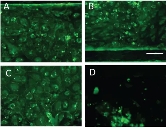
Once we had achieved stable cell viability within our NVU device over a 3-week time period, the next challenge was to evaluate how effectively it generated the mature, tight junc-tions critical to the BBB’s selective permeability. Previous culture methods for generating in vitroBBBs often lacked either the shear forces necessary to maintain a polarized and dif-ferentiated state within the endothelial cells,3,10,19 or the appropriate paracrine factors from astrocytes and pericytes for stable and selective function of tight junctions. Experiments using gravity-fed microfluidic chambers show that with the addition of flow, and exposure to pericyte- or astrocyte-conditioned media, we can establish high levels of tight junction stain-ing that are stable over the course of two weeks after the tight junctions have formed (Figures 3(a)–3(d)). When ZO-1 staining was quantified using mean greyscale intensity at the cell border of thirty different cell-to-cell interactions, we found that pericyte-conditioned media significantly increased ZO-1 intensity (p¼0.002, N¼30) (Figure 3(e)). Astrocyte-conditioned media trended toward an increase but was not statically significant due to vari-ability (Supplementary Figure 3).69 It should be noted, however, that flow alone was suffi-cient for tight junction staining to be visible. Further, all cultures required the presence of at least 5% serum to maintain cell viability. These experiments suggest that our NVU device, which combines both the shear force of flow and access to paracrine factors from pericytes and astrocytes, is ideal for generating and maintaining tight junctions58–60 in brain-derived endothelial cells.
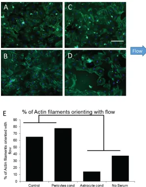
In addition to markers for tight junction formation, another vital component for BBB for-mation is polarization of the endothelial cells in the direction of flow.4,19,61To evaluate cell po-larity, actin filaments in endothelial cells under our various culture conditions were stained with phalloidin. We then assessed the percent of actin filaments whose orientation was parallel to the direction of flow. Filaments were considered to have an orientation parallel to flow if they were within 32.5 (60 arc) of the flow vector (Figures4(a)–4(d)). Control cultures under flow show 65% of actin filaments orienting in the direction of flow. This number increased to 78% with the addition of pericyte-conditioned media. Interestingly, astrocyte-conditioned media encouraged polarization of actin filaments perpendicular to the direction of flow. Cells main-tained in no-serum media showed little, if any, actin bundle formation at all (Figure 4(e)). These findings demonstrate the need for flow, serum, and pericyte-generated factors for the for-mation and orientation of actin filaments in the direction of flow in the development of a mature BBB.
cellular barrier only to the mechanical properties of the device, while the second is a biologi-cally relevant disruption (but does not destroy the BBB such that the graphs in Figure 2 have differing scales). In combination, these experiments demonstrate the generation of a functional cellular barrier within our NVU.
Next, we next undertook to show that active transport—another critical component of the BBB often overlooked in cellular BBB models46—could be shown in our system. To this end, we used ascorbate, which is known both to tighten the BBB64 and be actively transported across the barrier,65,66 as an indication of active transport. In looking at ascorbate concentration over time, we saw a significant increase in all four NVUs tested (p¼0.01) (Figure 6(a)). In contrast, FITC-dextran diffusion across the barrier was significantly reduced (p¼0.0012) by the addition of ascorbate, and then remained steady over time (Figure6(b)). Since diffusion cannot account for the increase in ascorbate on the brain side, this is an indication of active transport.
[image:10.612.154.452.96.479.2]FIG. 5. FITC-dextran diffusion across the complete NVU BBB with all four cell types. (a) The concentration of 70 kD FITC-dextran and (b) 10 kD dextran in the vascular chamber is significantly less than across the membrane in the brain chamber (both p¼0.01, N¼6), as compared to the device whose cells were permeabilized with Triton. (c) Glutamate ex-posure for 1 h significantly increases the concentration of 10 kD FITC-dextran across the membrane (p¼0.01, N¼6).
[image:11.612.188.430.407.697.2]evaluate resistance across the endothelial cell membrane (Supplementary Figure 2)69 at a range of frequencies over the time course in which NVUs were in cell culture. As was seen with stain-ing for tight junction markers, there is a significant increase in TEER around Day 12 of approxi-mately 30% (p¼0.05) (Figure 7(a)). The percent increase is typical of reports for TEER and tight junctions,51although our values are higher, as the NVU itself has a high natural impedance. This correlates well with the histology verifying tight junction formation (Figure 3). In addition to detecting tight junction formation, TEER was also useful for evaluating cell viability. In devi-ces in which perfusion was occluded by 50% at Day 14 in culture, TEER showed a large drop at Day 21, which was later shown to correlate with cell survival (Figure7(b)). When tight junctions (but notcell survival) were impaired via cold shock of 33C for 12 h, TEER decreased signifi-cantly (p¼0.001) (Figure 7(c)). Furthermore, these measures of impedance show that the NVU device acts as a capacitor, with its peak impedance between 15–20 kHz, and that we can use the
shape of this capacitance to monitor the health of our devices over time (Figure7(d)). These find-ings demonstrate not only the reliability of our custom TEER device in our NVU but also show that our BBB is functioning as expected with regard to its endothelial cell resistance.
IV. LIMITATIONS
One of the limitations of our approach was the use of PDMS to create the NVU, given the propensity of hydrophobic molecules to adsorb to the PDMS.67,68We are proceeding to develop an NVU that is fabricated out of harder thermoplastics to avoid this problem.
The measurement of TEER in a transwell device benefits from the large volume of culture media on both sides of the membrane, in that the conductivity of the media ensures that each side of the membrane is an electrical isopotential, and hence, a four-probe TEER measurement records the potential drop across the membrane. With microfluidic devices, the access imped-ance of the media in the narrow channels can be significant, and the measurement of TEER then corresponds to the measurement of the properties of a distributed electrical cable with a short length constant. The TEER measurement is then most sensitive to the membrane proper-ties closest to the current injection electrodes.50 While our TEER measurement demonstrates the expected decrease in barrier permeability as the cells grow to confluence and form tight junctions, the exact extent of the region of the barrier being quantified is as yet unknown. For this reason, we believe that the FITC-dextran measurements may be more representative of the barrier function over the entire membrane in this type of NVU.
V. CONCLUSION
Our NeuroVascular Unit is a novel organ-on-a-chip bioreactor that combines microfluidics and three-dimensional cell culture to successfully recreate structure and behavior of the BBB and is a substantial improvement for modeling the human BBB. This unique microfluidic de-vice provides an environment for all cell types involved in BBB formation, the shear forces necessary for barrier formation, and the paracrine factors needed for long-term stable differen-tiation of the BBB. This device also provides the structures necessary for growing human neu-rons, so that the effects of drugs on neuronal function can be evaluated in the context of a BBB to account for drug permeability and effects on the BBB itself. The dual perfusion nature of this device allows for manipulation of either side of the BBB, as well as differential delivery of drugs and nutrients to either the vascular or the brain chamber. Taken together, these innova-tions provide a novel platform for modeling of BBB function and testing of drug toxicity and permeability with regard to the CNS.
ACKNOWLEDGMENTS
Funding for this work was provided in part by NIH/NIEHS R1 ES016931 (A.B.B.), NIH DK50435 (J.M.M.), and, through the NIH Common Fund, NCATS Grant No. 5UH3TR000491-04 (J.P.W.). We thank Dr. Hak-Joon Sung for his willingness to explore electrospun barrier membranes and the use of his lab’s microplate fluorimeter, Daniel A. Balikov for the technical assistance with the fluorimeter, and Allison Price for her editorial assistance. We appreciate detailed discussions with Dr. Damir Janigro, particularly with regard to the cable properties of small channel BBB models.
1A. Al Ahmad, C. B. Taboada, M. Gassmann, and O. O. Ogunshola,J. Cereb. Blood Flow Metab.31(2), 693 (2011). 2
E. Vandenhaute, L. Dehouck, M. C. Boucau, E. Sevin, R. Uzbekov, M. Tardivel, F. Gosselet, L. Fenart, R. Cecchelli, and M. P. Dehouck,Curr. Neurovasc. Res.8(4), 258 (2011).
3
L. Cucullo, M. Hossain, V. Puvenna, N. Marchi, and D. Janigro,BMC Neurosci.12(1), 40 (2011). 4
B. Germann, W. Neuhaus, R. Hofer-Warbinek, and C. R. Noe, Pharmazie63(4), 303 (2008). 5
Y. Molino, F. Jabes, E. Lacassagne, N. Gaudin, and M. Khrestchatisky, J. Visualized Exp.2014, e51278. 6
R. Shawahna, X. Decleves, and J. M. Scherrmann,Curr. Drug Metab.14(1), 120 (2013). 7
8
N. Filipovic, K. Ghimire, I. Saveljic, Z. Milosevic, and C. Ruegg, “Computational modeling of shear forces and experi-mental validation of endothelial cell responses in an orbital well shaker system,”Comput. Methods Biomech. Biomed. Eng.(published online 2015).
9P. Naik and L. Cucullo,J. Pharm. Sci.
101(4), 1337 (2012). 10
R. C. Brown, A. P. Morris, and R. G. O’Neil,Brain Res.1130(1), 17 (2007). 11
L. Cucullo, B. Aumayr, E. Rapp, and D. Janigro, Curr. Opin. Drug Discovery Dev.8(1), 89 (2005). 12
X. F. Cao, H. X. Lin, L. Muskhelishvili, J. Latendresse, P. Richter, and R. H. Heflich,Respir. Res.16, 30 (2015). 13H. Vernon, K. Clark, and J. P. Bressler,Methods Mol. Biol.
758, 153 (2011). 14
P. D. Bowman, A. L. Betz, D. Ar, J. S. Wolinsky, J. B. Penney, R. R. Shivers, and G. W. Goldstein,In Vitro17(4), 353 (1981).
15
P. J. Gaillard, L. H. Voorwinden, J. L. Nielsen, A. Ivanov, R. Atsumi, H. Engman, C. Ringbom, A. G. de Boer, and D. D. Breimer,Eur. J. Pharm. Sci.12(3), 215 (2001).
16
Z. Z. Sun, M. Worden, Y. Wroczynskyj, V. Yathindranath, J. van Lierop, T. Hegmann, and D. W. Miller,Int. J. Nanomed.9, 3013 (2014).
17
Y. Takeshita, B. Obermeier, A. Cotleur, Y. Sano, T. Kanda, and R. M. Ransohoff,J. Neurosci. Methods 232, 165 (2014).
18
Z. Q. Zhang, A. J. McGoron, E. T. Crumpler, and C. Z. Li,Appl. Biochem. Biotechnol.163(2), 278 (2011). 19
L. Cucullo, M. Hossain, W. Tierney, and D. Janigro,BMC Neurosci.14, 18 (2013). 20
S. Nakagawa, M. A. Deli, H. Kawaguchi, T. Shimizudani, T. Shimono, A. Kittel, K. Tanaka, and M. Niwa,Neurochem. Int.54(3–4), 253 (2009).
21
A. S. Easton and N. J. Abbott,Brain Res.953(1–2), 157 (2002). 22
R. D. Hurst and I. B. Fritz,J. Cell Physiol.167(1), 89 (1996). 23
M. Kusch-Poddar, J. Drewe, I. Fux, and H. Gutmann,Brain Res.1064(1–2), 21 (2005). 24C. Moraes, G. Mehta, S. C. Lesher-Perez, and S. Takayama,Annu. Biomed. Eng.
40(6), 1211 (2012). 25
A. D. van der Meer and A. van den Berg,Integr. Biol.4(5), 461 (2012). 26
J. P. Wikswo,Exp. Biol. Med.239, 1061 (2014). 27
J. P. Wikswo and A. P. Porter,Exp. Biol. Med.240, 3 (2015).
28L. M. Griep, F. Wolbers, B. de Wagenaar, P. M. ter Braak, B. B. Weksler, I. A. Romero, P. O. Couraud, I. Vermes, A. D. van der Meer, and A. van den Berg,Biomed. Microdevices15(1), 145 (2013).
29
B. Prabhakarpandian, M. C. Shen, J. B. Nichols, I. R. Mills, M. Sidoryk-Wegrzynowicz, M. Aschner, and K. Pant,Lab Chip13(6), 1093 (2013).
30R. Booth and H. Kim,Annu. Biomed. Eng.
42(12), 2379 (2014). 31
J. A. Kim, H. N. Kim, S. K. Im, S. Chung, J. Y. Kang, and N. Choi,Biomicrofluidics9(2), 024115 (2015). 32
J. Wikswo, E. L. Curtis, Z. E. Eagleton, B. C. Evans, A. Kole, L. H. Hofmeister, and W. J. Matloff,Lab Chip13(18), 3496 (2013).
33D. C. Duffy, J. C. McDonald, O. J. A. Schueller, and G. M. Whitesides,Anal. Chem.
70(23), 4974 (1998). 34
K. Aran, L. A. Sasso, N. Kamdar, and J. D. Zahn,Lab Chip10(5), 548 (2010). 35
Y. Liu, D. Markov, J. Wikswo, and L. McCawley,Biomed. Microdevices13(5), 837 (2011). 36
S. M. Chambers, C. A. Fasano, E. P. Papapetrou, M. Tomishima, M. Sadelain, and L. Studer,Nat. Biotechnol.27(3), 275 (2009).
37
Y. C. Shi, P. Kirwan, and F. J. Livesey,Nat. Protoc.7(10), 1836 (2012). 38
Y. C. Shi, P. Kirwan, J. Smith, H. P. C. Robinson, and F. J. Livesey,Nat. Neurosci.15(3), 477 (2012). 39
A. A. Aboud, A. M. Tidball, K. K. Kumar, M. D. Neely, B. Y. Han, K. C. Ess, C. C. Hong, K. M. Erikson, P. Hedera, and A. B. Bowman,Neurobiol. Dis.73, 204 (2015).
40
A. M. Tidball, M. R. Bryan, M. A. Uhouse, K. K. Kumar, A. A. Aboud, J. E. Feist, K. C. Ess, M. D. Neely, M. Aschner, and A. B. Bowman,Hum. Mol. Genet.24(7), 1929 (2015).
41
K. Watanabe, M. Ueno, D. Kamiya, A. Nishiyama, M. Matsumura, T. Wataya, J. B. Takahashi, S. Nishikawa, S. Nishikawa, K. Muguruma, and Y. Sasai,Nat. Biotechnol.25(6), 681 (2007).
42
C. Boissart, A. Poulet, P. Georges, H. Darville, E. Julita, R. Delorme, T. Bourgeron, M. Peschanski, and A. Benchoua,
Transl. Psychiatry3, e294 (2013). 43
N. J. Lamas, B. Johnson-Kerner, L. Roybon, Y. A. Kim, A. Garcia-Diaz, H. Wichterle, and C. E. Henderson,PLoS One 9(10), e110324 (2014).
44
F. Roloff, H. Scheiblich, C. Dewitz, S. Dempewolf, M. Stern, and G. Bicker,PLoS One10(2), e0118536 (2015). 45
X. Tang, L. Zhou, A. M. Wagner, M. C. Marchetto, A. R. Muotri, F. H. Gage, and G. Chen,Stem Cell Res.11(2), 743 (2013).
46U. Bickel,NeuroRX
2(1), 15 (2005). 47
A. Hoffmann, J. Bredno, M. Wendland, N. Derugin, P. Ohara, and M. Wintermark,Transl. Stroke Res.2(1), 106 (2011). 48
J. M. May, Z. C. Qu, and S. Mendiratta,Arch. Biochem. Biophys.349(2), 281 (1998). 49
E. Sarro, M. Lecina, A. Fontova, C. Sola, F. Godia, J. J. Cairo, and R. Bragos,Biosens. Bioelectron.31(1), 257 (2012). 50M. Odijk, A. D. van der Meer, D. Levner, H. J. Kim, M. W. van der Helm, L. I. Segerink, J. P. Frimat, G. A. Hamilton,
D. E. Ingber, and A. van den Berg,Lab Chip15(3), 745 (2015). 51
K. Benson, S. Cramer, and H. J. Galla,Fluids Barriers CNS10(1), 5 (2013). 52
K. A. Newell-Litwa, M. Badoual, H. Asmussen, H. Patel, L. Whitmore, and A. R. Horwitz,J. Cell Biol.210(2), 225 (2015).
53
S. McCue, D. Dajnowiec, F. Xu, M. Zhang, M. R. Jackson, and B. L. Langille,Circ. Res.98(7), 939 (2006). 54
B. Wojciak-Stothard and A. J. Ridley,J. Cell Biol.161(2), 429 (2003). 55
J. H. Zar,Biostatistical Analysis, 2nd ed. (Prentice-Hall, Englewood Cliffs, NJ, 1984).
56K. Hatherell, P. O. Couraud, I. A. Romero, B. Weksler, and G. J. Pilkington,J. Neurosci. Methods
199(2), 223 (2011). 57
58
K. Yamagata, M. Tagami, Y. Nara, M. Mitani, A. Kubota, H. Fujino, F. Numano, T. Kato, and Y. Yamori,Clin. Exp. Pharmacol. Physiol.24(9–10), 710 (1997).
59
W. Pan, K. P. Stone, H. Hsuchou, V. K. Manda, Y. Zhang, and A. J. Kastin,Curr. Pharm. Des.17(33), 3729 (2011). 60F. Shimizu, Y. Sano, K. Saito, M. A. Abe, T. Maeda, H. Haruki, and T. Kanda,Neurochem. Res.
37(2), 401 (2012). 61
E. Gonzalez-Burgos, M. E. Carretero, and M. P. Gomez-Serranillos,Planta Med.79(16), 1545 (2013).
62D. B. Stanimirovic, M. Bani-Yaghoub, M. Perkins, and A. S. Haqqani,Expert Opin. Drug Discovery10(2), 141 (2015). 63
T. G. Walsh, R. P. Murphy, P. Fitzpatrick, K. D. Rochfort, A. F. Guinan, A. Murphy, and P. M. Cummins,J. Cell Physiol.226(11), 3053 (2011).
64
J. M. May and Z. C. Qu,Free Radical Res.44(11), 1359 (2010).
65D. B. Agus, S. S. Gambhir, W. M. Pardridge, C. Spielholz, J. Baselga, J. C. Vera, and D. W. Golde,J. Clin. Invest.
100(11), 2842 (1997).
66J. M. May, Z. C. Qu, and H. Qiao,Am. J. Physiol. Cell297(1), C169–C178 (2009). 67
M. W. Toepke and D. J. Beebe,Lab Chip6(12), 1484 (2006). 68
J. D. Wang, N. J. Douville, S. Takayama, and M. ElSayed,Annu. Biomed. Eng.40(9), 1862 (2012). 69