This is a repository copy of
Real-Time Imaging System using a 12-MHz Forward-Looking
Catheter with Single Chip CMUT-on-CMOS Array
.
White Rose Research Online URL for this paper:
http://eprints.whiterose.ac.uk/101036/
Version: Accepted Version
Proceedings Paper:
Tekes, C, Xu, T, Carpenter, TM et al. (7 more authors) (2015) Real-Time Imaging System
using a 12-MHz Forward-Looking Catheter with Single Chip CMUT-on-CMOS Array. In:
Proceedings of the 2015 IEEE International Ultrasonics Symposium (IUS). 2015 IEEE
International Ultrasonics Symposium (IUS), 21-24 Oct 2015, Taipei, Taiwan. IEEE . ISBN
978-1-4799-8182-3
https://doi.org/10.1109/ULTSYM.2015.0521
(c) 2015, IEEE. Personal use of this material is permitted. Permission from IEEE must be
obtained for all other uses, in any current or future media, including reprinting/republishing
this material for advertising or promotional purposes, creating new collective works, for
resale or redistribution to servers or lists, or reuse of any copyrighted component of this
work in other works.
[email protected] https://eprints.whiterose.ac.uk/
Reuse
Unless indicated otherwise, fulltext items are protected by copyright with all rights reserved. The copyright exception in section 29 of the Copyright, Designs and Patents Act 1988 allows the making of a single copy solely for the purpose of non-commercial research or private study within the limits of fair dealing. The publisher or other rights-holder may allow further reproduction and re-use of this version - refer to the White Rose Research Online record for this item. Where records identify the publisher as the copyright holder, users can verify any specific terms of use on the publisher’s website.
Takedown
If you consider content in White Rose Research Online to be in breach of UK law, please notify us by
Real-Time Imaging System using a 12-MHz
Forward-Looking Catheter with Single Chip
CMUT-on-CMOS Array
Coskun Tekes
1, Toby Xu
1, Thomas M. Carpenter
1, Sebastian Bette
2, Uwe Schnakenberg
2, David Cowell
3, Steven
Freear
3, Ozgur Kocaturk
4, Robert J. Lederman
4, F. Levent Degertekin
11
George W. Woodruff School of Mechanical Engineering, Georgia Institute of Technology, Atlanta, GA, 2Institute of Materials in Electrical Engineering, RWTH Aachen University, Aachen, Germany, 3School of Electronic and Electrical Engineering, University of Leeds, Leeds, United Kingdom, 4Division of Intramural Research, National Institute of Health, Bethesda, Maryland,
USA
Abstract— Forward looking (FL) imaging catheters would be an important tool for several intravascular ultrasound (IVUS) and intracardiac echocardiography (ICE) applications. Single chip capacitive micromachined ultrasonic transducer (CMUT) arrays fabricated on front-end CMOS electronics with simplified electrical interconnect have been previously developed for highly flexible and compact catheters. In this study, we present a custom built real time imaging system utilizing catheters with single chip CMUT-on-CMOS arrays and show initial imaging results. The fabricated array has a dual-ring structure with 64 transmit (Tx) and 56 receive (Rx) elements. The CMUT arrays fit on a 2.1 mm diameter circular region with all the required front-end electronics. The device operates at 12 MHz center frequency and has around 20 V collapse voltage. The single-chip system requires 13 external connections including 4 Rx channels and power lines. The electrical connections to micro cables in the catheter are made from the top side of the chip using polyimide flex tapes. The device is placed on a 6-Fr catheter shaft and secured with a medical grade silicon rubber. For real time data acquisition, we developed a custom design FPGA based imaging platform to generate digital control sequences for the chip and collect RF data from Rx outputs. We performed imaging experiments using wire phantoms immersed in water to test the real time imaging system. The system has the potential to generate images at 32 fps rate with the particular catheter. The overall system is fully functional and shows promising image performance.
Keywords- Intravascular; ultrasound; intracardiac echocariography; single chip; real time; CMUT; Forward Looking.
I. INTRODUCTION
Imaging catheters utilized in intravascular ultrasound (IVUS) and intracardiac echocardiography (ICE) imaging have become extremely popular for more than a decade. Miniaturized imaging probes, which can be placed inside the heart chamber and arteries, would assist physicians to guide interventions for structural heart diseases and electrophysiology, and monitor coronary artery diseases [1]. As an alternative tool to transesophageal echocardiogram (TEE), ICE catheter may provide similar imaging performance without the need for general anesthesia. It may also reduce fluoroscopy exposure duration while allowing shorter procedure time for the physician and early recovery for the patient. ICE catheters
are generally used to enhance accurate placement of interventional catheters, such as ablation for atrial fibrillation, and guide transcatheter aortic valve implantation. In IVUS procedures, imaging catheters are useful to determine vessel sizing and help stent deployment [2, 3].
1D imaging arrays can only generate side-view 2D cross-sectional of the arteries in IVUS and single plane image of the heart structures in ICE imaging. This requires additional steering or pullback mechanisms to obtain the 3D view of the heart structures to a certain extent. Forward looking 2D imaging arrays have the potential to visualize the true 3D volumetric views of the heart in real time. This provides better anatomic information, diagnosing severely occluded arteries, placement and utilizing the guidewire and additional interventional tools during the procedure [4-6].
To implement a forward looking imaging tool on small size catheters, the devices are required to be extremely miniaturized which can handle hundreds of transducer elements with their front-end electronics. We have previously developed a forward-looking single-chip CMUT-on-CMOS system simplified electrical interconnects for highly flexible and compact catheters [5]. In this study, we present a brief description of the single-chip system and the catheter assembly steps as well as the real time data acquisition and imaging system.
II. METHOD
A. Dual Ring CMUT Arrays
are monolithically fabricated on pre-processed CMOS wafers with low temperature CMOS-compatible fabrication process. With a gap thickness of 50 nm, chosen to reduce operating bias voltages, a collapse voltage of 20 V is obtained. 120-nm of HfO2 as an insulation layer is used to improve transmit output
pressure [7]. The micrograph of the single chip system including the CMUT arrays monolithically fabricated on top of the CMOS IC is shown in Fig. 2.
B. Integrated Electronics
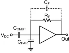
To implement the single chip system, we designed a custom front-end integrated circuit (IC) using TSMC’s
0.35-m CMOS process on 8-inch silicon wafer reticle. This particular system requires 13 external connections including IC power lines, 4 Rx channel output, digital control signals and CMUT bias voltages. Each Rx element is connected to a dedicated low noise 50-kΩ resistor feedback transimpedance amplifier (TIA) shown in Fig. 3. To readout the received signals from 4 output channels, each quarter block of the Rx elements are connected to 16x1 multiplexer which then route receiver channels to the 4 output buffers. The digital circuitry handles the receiver multiplexing during individual active Tx element firing to cycle through all the Rx elements in each Rx block. After the active Tx pulser finishes transmitting by 16 times, the digital control switches to a different pulsing element in the active transmit block and the receive operation is repeated. After all Tx elements are switched around the array the data collection is completed. Since the device has 56 Rx elements, for each active Tx element, the last 2 pulses are not actively received.
The chip has 64 Tx pulsers which can be selected to be active using a master select circuitry and de-multiplexers. Due to the limitation of used CMOS fabrication technology, for this particular system, only a 12.5 V pulse amplitude can be achieved. All of the active circuitry and the CMUT array fit into a size of 2.1-mm diameter silicon donut with a 500-μm gap left inside for the guide wire.
C. Flex Tape Fabrication and Interconnects
To connect the CMUT-on-CMOS chips to micro cables, polyimide flex tapes are designed and fabricated. They contain
15 circularly arranged gold bumps on one side and 16 gold pads one the other side spread over the 4 legs of the tapes. The gold bumps are electrically connected by buried conductive traces of gold to 13 of the 16 gold pads. During the production process the polyimide (PI-2525, HD MicroSystems) is spin coated onto a 4” wafer of silicon dioxide with a titanium aluminum titanium sacrificial layer (30 nm Ti / 1000 nm Al / 30 nm Ti), photolithographically structured and polymerized in a nitrogen oven at 400°C. The first layer of the polyimide is opened in the shape of the gold pads towards the wafer. After the physical vapor deposition of a chromium gold plating base (30 nm Cr/100 nm Au) and its structuring by photolithography, an electroplating step of 5 m gold is carried out. A second polyimide layer buries the conductive traces and forms the mask for the formation of the circularly arranged gold bumps. They are formed by a second electroplating step in which the height of the gold is chosen to be more than 5 m, which is the thickness of the second polyimide layer. The flex tapes are separated by etching the aluminum sacrificial layer with hydrochloric acid (2 %). The titanium interlayer is removed by a short etching step with hydrofluoric acid (1 %).
[image:3.595.309.557.59.170.2]The CMUT devices are mounted onto the flex tapes within a flipchip bonding process (Fig. 4). Therefore the anisotropic conduction epoxy (Elecolit® 3061, Panacol) is dispensed onto the 15 gold bumps and the area around them on the flex tapes. The device is adjusted to the flex tape and pressed upside down into the epoxy. The sensitive area of the device is left free by the flex tape and the glue. The following heating step cures the epoxy and establishes the electrical connections. After merging the chip and the flex tape, the four copper cables are wired to the tapes. Each of them consisting of 4 copper wires is connected to the pads of one of the flex tapes legs (Fig. 5). The color coded wires are stripped manually and connected to the
[image:3.595.44.276.59.185.2]Figure 1. Conceptual drawing of a single-chip fully-integrated FL-IVUS imaging catheter based on a dual-ring CMUT array monolithically integrated with the complete front-end CMOS IC
Figure 2. Micrograph of the single chip dual ring array (left) and IC with receive and transmit electronics with the digital control circuitry (right).
[image:3.595.374.495.221.315.2]pads via micro resistive welding (resistive welding system HF25, UNITEK EQUIPMENT). A transparent globe top encapsulation (Vitralit® 4732 VT, Panacol) stabilizes the
connections mechanically.
D. Catheter Assembley
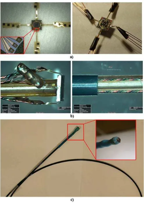
The 6 Fr catheter shaft was composed of two coaxial layers. While the inner layer has metal braiding layer to enhance the overall catheter pushability and torquability, the outer layer was designed as a jacketing layer to insulate micro cables. The inner layer shaft has 4 side grooves for embedding the twisted micro cables into the catheter wall. The single chip CMUT-on-CMOS arrays was placed on the distal end of the inner layer and fixed by using medical grade UV curing adhesive (CTH 202, Dymax Inc., USA) (Fig 5-a). The micro cables extended from the polyimide interconnect/cable interface were placed into the dedicated grooves over the inner layer. The final jacketing layer (0,072” OD, 0.064” ID) was advanced over the inner layer until the distal tip reaches to the polyimide interconnect /cable interface (Fig 5-b). The both layers were fused together by using polymer reflowing technique until the overall catheter length is 100 cm. The distal tip of the catheter was coated with medical grade one component epoxy (Epo-Tek Inc., USA) to capsulate the interconnect pads of the single chip CMUT-on-CMOS arrays.
E. Data Acquisition System
For real time data acquisition, we developed an FPGA (Altera Stratix V) based imaging platform to generate digital control sequences for the chip and collect RF data from Rx outputs (Fig. 6). The RF signals are amplified and digitized using an 80 MHz ADC (TI AFE5807). The incoming data is fed into the FPGA with 512 MB capacity. The data is post processed and transferred to a PC via PCI Exp. data link with a speed of 14 Gbps.
III. RESULTS
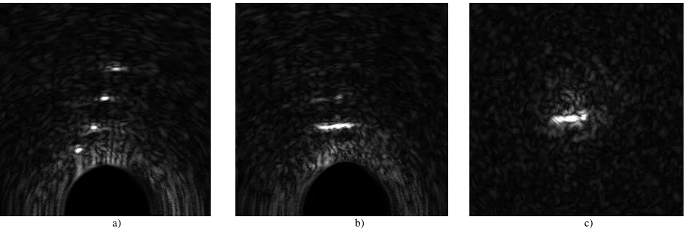
[image:4.595.310.558.51.402.2]We performed initial imaging experiments with single-chip forward looking catheter using 100- m wire phantoms immersed in water to test the catheter with real time imaging system. The wires located horizontally along y-axis from a depth of 3.2 mm to 7 mm. During the experiment, we used a
Figure 4. Conceptual drawing of flex tape to CMUT bonding process.
[image:4.595.37.289.60.162.2]Figure 5. Catheter assembly process. a) Flex tape and micro cable assembly, b) catheter assembly, and c) final catheter.
[image:4.595.317.550.460.615.2]Tx bias voltage of 18 V with 12.5 V unipolar pulse. The clock signal to synchronize the chip and pulse signal to trigger the on-chip pulsers in CMUT-on-CMOS system were generated by FPGA. The pulse width was adjusted as 43.75 ns. In receive, we applied a 17-V bias voltage which is close to 90% of collapse. We collected RF A-scans from all Tx-Rx element combinations in 1024 clock cycles. The data stored in FPGA memory transferred to PC where image reconstruction was performed by a custom RF beamforming software using synthetic phased array technique.
We reconstructed cross-sectional B-mode images in xz
plane and yz plane, and C-mode image at 4.5 mm depth. The images with 30 dB dynamic range are presented in Fig. 8. For this particular test catheter implementation, we averaged the RF data 16 times to overcome low SNR on echo signals. However, the system has the potential to generate images at 32 fps rate with the particular catheter.
IV. CONCLUSION
In this paper, we have presented the implementation of a forward looking catheter with our single chip CMUT-on-CMOS system. The overall system is fully functional and shows promising image performance. The single-chip forward looking imaging system maintaining the flexibility of the catheter tip demonstrate the feasibility of the approach. We are currently working on a higher speed chip with improved SNR to test the catheter with in vivo phantoms.
ACKNOWLEDGMENT
This work was supported by NIH grants HL121838 and EB010070.
REFERENCES
[1] M. Bhaya, F. O. Mutluer, E. Mahan, L. Mahan, M. C. Hsiung, W. H. Yin, et al., "Live/Real time three-dimensional transesophageal echocardiography in percutaneous closure of atrial septal defects," Echocardiography, vol. 30, pp. 345-53, Mar 2013.
[2] R. J. Siegel, H. Luo, and S. Biner, "Transcatheter valve repair/implantation," Int J Cardiovasc Imaging, vol. 27, pp. 1165-77, Dec 2011.
[3] Z. M. Hijazi, K. Shivkumar, and D. J. Sahn, "Intracardiac echocardiography during interventional and electrophysiological cardiac catheterization," Circulation, vol. 119, pp. 587-96, Feb 3 2009.
[4] A. Nikoozadeh, I. O. Wygant, D. S. Lin, O. Oralkan, K. Thomenius, A. Dentinger, et al., "Intracardiac Forward-Looking Ultrasound Imaging Catheters Using Capacitive Micromachined Ultrasonic Transducers," Acoustical Imaging, Vol 30, vol. 30, pp. 203-210, 2011.
[5] G. Gurun, C. Tekes, J. Zahorian, T. Xu, S. Satir, M. Karaman, et al., "Single-chip CMUT-on-CMOS front-end system for real-time volumetric IVUS and ICE imaging,"
IEEE Trans Ultrason Ferroelectr Freq Control, vol. 61, pp.
239-50, Feb 2014.
[6] C. Tekes, J. Zahorian, G. Gurun, S. Satir, T. Xu, M. Hochman, et al., "Volumetric imaging using single chip integrated CMUT-on-CMOS IVUS array," Conf Proc IEEE Eng Med Biol Soc, vol. 2012, pp. 3195-8, 2012.
[7] T. Xu, C. Tekes, and F. Degertekin, "CMUTs with high-K atomic layer deposition dielectric material insulation layer,"
IEEE Trans Ultrason Ferroelectr Freq Control, vol. 61, pp.
2121-31, Dec 2014.
[image:5.595.48.534.52.216.2]a) b) c)