This is a repository copy of
Switch access to technology - A comprehensive Guide.
.
White Rose Research Online URL for this paper:
http://eprints.whiterose.ac.uk/10291/
Monograph:
Judge, Simon and Colven, David (2006) Switch access to technology - A comprehensive
Guide. Manual. The ACE Centre , 92 Windmill Road Headington Oxford OX3 7DR.
[email protected]
https://eprints.whiterose.ac.uk/
Reuse
Unless indicated otherwise, fulltext items are protected by copyright with all rights reserved. The copyright
exception in section 29 of the Copyright, Designs and Patents Act 1988 allows the making of a single copy
solely for the purpose of non-commercial research or private study within the limits of fair dealing. The
publisher or other rights-holder may allow further reproduction and re-use of this version - refer to the White
Rose Research Online record for this item. Where records identify the publisher as the copyright holder,
users can verify any specific terms of use on the publisher’s website.
Takedown
If you consider content in White Rose Research Online to be in breach of UK law, please notify us by
Switch access
to technology
A comprehensive guide
The authors would like to thank the many people who over the years have contributed new ideas to this ield. Thanks in particular are due to the staff of the ACE Centre, CALL Centre and ACT who have given much useful feed-back and shared their considerable practical experience.
We also acknowledge the group who came together to create the original document, A Common Terminology for Switch Controlled Software1, on which this one is based. That group being Mike Detheridge, David King, Chris Page, Peter Head, Patrick Poon, Stan Cocking, Roddy Boyes, Robin Be-ste, Chris Hopkins, Paul Skinner, Jeff Wardle, Paul Nisbet and Robert Wills.
David Colven [email protected] Simon Judge [email protected]
©2006 ACE Centre Advisory Trust and ACT (Access to Communication in Technology)
First edition published June 2006
Published by the ACE Centre Advisory Trust 92 Windmill Road
Headington Oxford OX3 7DR
www.ace-centre.org.uk
Switch access
to technology
Contents
Introduction
1
Terminology
3
Alternative Access Systems
5
The Spectrum of Input ... 5
Switches ... 5
Direct input devices ... 6
Alternative Pointing Devices ... 6
Keyboards ... 6
Characteristics of Users
7
Motor Control Problems ... 7Visual Problems ... 7
Cognitive involvement ... 7
Developmental Needs ... 8
The User Interface for Switching
9
Presenting choices ... 9Selection sets ... 9
Single line presentation ... 10
Grid presentation ... 10
Flip chart presentation ... 10
Pop up presentation ... 10
Custom presentation ... 10
Items ... 10
Grouping ... 10
Highlighting ...11
Feedback and Output ...12
Aesthetics ...12
Control and Selection
13
Scanning Sequencing Methods ...13Simple Scan ...13
Group Scan ...14
Directed Scan ...15
Highlighter movement control ...15
Autoscan ...15
User Scan ...16
Step Scan Switch Alternation (Swap Switch) ...17
Manipulating the Highlighter Movement ...18
Auto – Restart, Starting and Restarting ...18
Repeating items ...18
Dealing with errors ...18
Error items: ...18
Scan errors: ...18
Selection ...19
Dwell Selection ...19
Switch Encoded Selection ...19
Combinatorial Encoding: ...19
Time Encoded Selection ... 20
Switch Actions ... 20
Type Ahead ... 20
Numbers of Switches ... 20
Half Switches ... 21
Timing and Input Filtering
23
Timing parameters ... 23Scan Time ... 23
Initial Scan Time ... 23
Scan Pause ... 23
Dwell Time ... 24
Repeat Functions ... 24
Repeat Delay ... 24
Repeat Time ... 24
Auto-repeat ... 24
Input Filtering ... 24
Debounce Time ... 25
Acceptance time ... 25
Post-acceptance Time ... 25
Conclusions
27
Appendix 1: Connecting switches to a computer
29
Switch Software ... 29Ports ... 29
Switch Interfaces ... 30
USB ... 30
Keyboard ... 30
Parallel Port ... 30
Older Interfaces ... 30
Appendix 2: Switch control of systems
31
Appendix 3: Summary of Terminology
33
Appendix 4: Ports and interfaces for switch access
37
Data ile structures ... 40
User coniguration selection ... 40
Appendix 6:
41
Implementation of scanning within software
41
Minimum implementation ... 41Connections ... 41
Switches/Devices ... 41
Scanning methods ... 42
Small selection sets (less than 10 items) ... 42
Larger selection sets ... 42
Pull down menus ... 42
Point and click environments ... 42
Selected Resources
45
Resources ... 45You can skip this section if you are already familiar with scanning and as-sistive technology - you may wish to start from to the User Interface for Switching chapter on page 9.
Most of us take typing for granted, even if some of us aren’t very good at it. Most of us are also used to being able to speak, turn on the lights and be mobile – all normal interactions with the world. But for a signiicant part of the population some or all of the above are dificult or impossible. For some people their interactions with the world take place through a single switch – imagine having to control everything you want using a light switch. Small differences to how you use this switch will make a massive impact on your life! This is the reality for a number of people. Consider Stephen Hawking, or Jean-Dominique Bauby who wrote The Diving Bell and the Butterfly2 by blinking an eyelid.
Surely it’s only possible to control a single thing using a single switch? Not so. With the sacriice of time, it’s possible to control as many things as you want – be it the lights in your house, a virtual keyboard on a computer, a games console, or a communication aid.
Scanning is the answer to controlling many things by using a single indica-tion or switch: to scan a list of things, each item is presented to you one at a time, and you indicate (for example by blinking or pressing a switch) when the thing you want is presented. It’s a bit like a sushi bar, you can’t reach all the dishes from where you sit, and you have to wait until the one you want turns up in front of you.
Scanning isn’t actually that specialist – if you look you will see it all around you. With a single switch the speed at which you select things is under the control of a system, like the sushi bar moving at a continous rate. If you can use two or more switches then it may be easier to control the scan yourself. This is common on mainstream technologies such as television on-screen menus and mobile phone controls, and is also hidden in other things. You can, for example, access the Internet with just two keys, Tab and Return. Tab takes you from link to link, and Return chooses the link – try it out.
It usually requires specialist software to give a user effective scanning. There’s a range of software and devices, collectively known as Electronic Assistive Technology (EAT), that are designed for switch users. Whatever an EAT device looks like, it’s almost always controlled by software run on some sort of computer.
Introduction
Over the years, in order to give users lexible and eficient access to their environment, Assistive technology software engineers and practitioners have developed specialised scanning techniques for communication, envi-ronmental control, mobility and leisure activities. This document describes these techniques and the processes behind them.
Switch control of computers and other equipment via scanning systems is an area where a confusion of terms has grown up over the years. This paper contains a terminology lexicon which agrees as closely as possible to that currently used in the UK and within the English-speaking community. Where there are alternative terms, these are cross-referenced. Terms follow closely those published in A Common Terminology for Switch Controlled Software2. A summary of terms is also included in Appendix 3 (page 33).
Sticking to a deined terminology has several important advantages. Stand-ardisation is essential for any area that wishes to mature and grow:
It allows a constructive discussion on the topic and avoids confusion.
It allows standardised storage of parameters surrounding switch ac-cess, thus making ‘porting’ of users settings between software and ‘tailoring’ software easier.
It promotes the potential for a universal access module (as proposed by Lundlav et al3).
It encourages further research and development and ensures and en-sures that this is clearly deined.
Before looking at the various variables and characteristics of switch scan-ning in later sections, we’ll introduce a range of alternative input devices and some of the characteristics of users of such systems.
For ease, we’ll refer to ‘Software’ – however we are including any assistive technology incorporating switch access.
•
•
•
•
Terminology
“ Standardization is simply another aspect of cultural constraints. With standardization, once you have learned to drive one car, you feel
justiiably conident that you can
drive any car, any place in the world... When we have standardization of
our keyboard layouts, our input
and output formats, our operating systems, our text editors and word
processors, and the basic means of
operating any program, then suddenly
we will have a major breakthrough in usability”
Don Norman, The Psychology of Everyday Things4
Alternative
Access Systems
In this section we deal with alternative access systems – we describe the range of equipment used for alternative access to computers and other technology. In addition we describe the characteristics of some users of alternative access.
The spectrum of input
There is a considerable range of alternative access systems to assist users of technology and an even greater range of access dificulties that may present themselves. The following list is designed to give just an indication of this range. In this document we are principally considering the use of switch control.
[image:14.595.66.328.88.183.2]Input to a computer can be considered described on a spectrum or in terms of bandwidth: Touch typists and computer-aided-designers at one end, hunt-and-peck typists in the middle and switch users at the other end.
Fig 1: The input bandwidth spectrum
Switches
A person who may only have one or two reliable physical movements may be able to use switches if the switches are placed in the correct place. An enormous range of switches is available from many suppliers. The ACE Cen-tre website links to many of these suppliers’ sites.
Switches come in a large range of sizes and can be placed almost anywhere and accommodate most types of movement. The largest group of switches are for limb or head operation. These include simple lever or pressure switches that can be used with a single movement of any part of the body. Grip and thumb switches, pneumatic pressure switches, tilt or posture switches, touch and proximity switches and even ‘wobble’ sticks also exist.
Fig 2: A standard switch
This transmits just one bit of informa -tion: on or off. However for some people this is their means of interface with the world.
[image:14.595.68.377.482.574.2]Other switches can be operated by suck, blow, blink, muscle, sound or almost any other voluntary action.
Choosing switch settings for users
The number of switches a user needs is the principle setting, although this choice may change as the user progresses. All the other settings are gener-ally subsidiary; depending on the user’s other abilities and needs. Details of the settings needed for switch controlled scanning systems are document-ed in the Control and Selection chapter on page 13.
Direct input devices
Alternative Pointing Devices
These include mice, tracker balls, joysticks and touch sensitive screens and devices such as head or eye pointers. It must be noted there are two types of joysticks: the analogue joystick and the switched joystick, which is really a number of switches in ixed positions operated by a single lever.
Most software now uses the mouse pointer for control, often providing no alternative. The mouse not only requires moderate to good hand/eye co-or-dination but also very good ine motor control – and a wide range of users may struggle with its use. The use of alternative mice such as trackerballs and joysticks can alleviate some problems.
Keyboards
The standard keyboard can be regarded as a multiple switch bank. Alterna-tive conigurations of keyboards, one handed keyboards, keyguards, and other alternative physical keyboards exist.
[image:15.595.69.198.84.148.2]Users who are able to manipulate a mouse cursor but who are not able to use a conventional keyboard might use an On-Screen Keyboard.
Fig 3: Child using a touchscreen
Touch sensitive screens are commonly used as an alternative access device, as well as on ‘mainstream’ devices. Touchscreens are now very accurate
but require a very ine level of control on the part of the user. They can be
particularly useful for the developmen-tally young - giving direct and
immedi-ate access to ‘dynamic’ keyboards and
content.
Fig 4: Child using a concept Keyboard
The Concept Keyboard and Intellikeys are types of touch sensitive boards that can be conigured into any keyboard layout. Any number of keys and labels can be used (e.g. symbols, pictures etc). These membrane keyboards are very popular because of their lexibility of
input to the computer.
Characteristics
of Users
A wide range of disabilities and conditions (including old or young age) will affect people’s interaction with technology5. It is not possible to list all the conditions, their characteristics and how they effect someone’s access to technology – not least since each person is entirely unique. The sections below give a guide to some of the characteristics of users that are relevant to access.
Motor control problems
The ACE Centres’ work is focused on children and young people. 60% of the children seen at the ACE Centres have cerebral palsy, the majority of whom have severe athetosis. This means that their ine and/or gross motor control is often very poor and as a result they may only be able to use one or two switches. Regional Assistive Technology services, such as ACT, see a wide range of people, including adults with degenerative neurological conditions, such as Motor Neurone Disease (MND). People with MND and other conditions will experience deterioration in their physical ability whilst often retaining ine control of some muscles (e.g. a inger, or eyelid). In addition people with traumatic injuries (such as stroke or spinal cord injury) will experience sudden changes in their physical function maybe including complete paralysis of a majority of their body.
Visual problems
Some Assistive Technology users may have visual or visual perception prob-lems – these may be often be in conjunction with other probprob-lems and may be undiagnosed or even unrecognised. The implications of this to switch in-terfacing mainly impinge on the selection of scanning methods (see below); feedback through other media and aesthetic issues of size and contrast.
Cognitive involvement
The use of switches and the process of scanning can be a relatively complex task and different methods require a number of prerequisite skills. People with learning, memory, processing or other cognitive and learning prob-lems may have different needs (for example increased support or simpler structures) with respect to switching and scanning, compared with others.
Developmental needs
Users of switch controlled system do not remain static in their needs. Switch systems must, therefore remain lexible in terms of types of control, scanning and response so that they can always match the user’s needs.
A typical user would tend to move through a series of different control methods as they mature and develop. Their control may improve or deterio-rate. For example, at irst they may use single switch with cause and effect programs, they may then progress to making choices with a very slow sin-gle switch automatic scan. Alternatively, a two switch step scan where they have complete control of the scan with one switch and item selection with the second switch may be best.
Some people will develop suficient compensation or control in movement combined with learning and practice, so that their access through scanning can further improve in either speed and/or method.
However, this over-simpliication hides a range of needs that can be helped by quite subtle differentials in switch interfacing. In the next section we will illustrate the range of different methods of presentation of choices, before moving on to look at the different methods of choice selection. The applica-tion of these possible variables to provide an appropriate switch interface for a user is the black art of switch scanning.
In this section we explain the process of controlling the computer / software with switches. Users who access computers with one or two switches gen-erally do so by means of on-screen selection sets, also known as keyboards, grids or pages etc (there are other methods of providing a user-interface for switching, such as coded input). Items in the selection set are highlighted either one at a time or in groups to allow the user to choose the desired item. The different methods of layout are detailed in this section.
Presenting choices
To input information into a machine you need to have information pre-sented to you in a form that allows you to make an informed selection. For keyboard users this selection is through pressing a labelled key on the keyboard – this can be thought of as a bank of some 100 or so switches for which each switch represents a single possible item.
A disabled user may want to input the same information with just a single switch. To do this, time is introduced into the procedure – i.e. a sequence of items is presented to the user at a pre-deined rate, the desired item is selected by the user activating the switch at the appropriate time. Scanning is the process of presenting the possible items for selection. These methods are described in more detail in this section.
Selection sets
The set of all the items from which choices are made is called the selection set. At any one time it may be more appropriate to present only a sub-set (or group) of this – this is discussed further in the Control and Selection chapter on page 13.
If the number of items is larger than can be displayed on one screen (page) then further pages are required. The set can now be thought of as a book or card index rack with some items pro-viding links between the differ-ent pages/cards.
[image:18.595.67.376.87.182.2]The User Interface
for Switching
Fig 5: Sets subsets and items within a selection set
There are a number of ways of presenting a selection set to the user:
Single line presentation (see ig 6)
Where the visual representations are in a single simple line - ’line’ is used rather than ‘row’ so as to include all possible orientations.
Grid presentation (see ig 7)
When there are large numbers of items it can be convenient to present them in the form of a two-dimensional grid.
Flip chart presentation
Individual items, or some parts of the selection set, may be displayed one at a time in sequence rather like turning the cards in a rotary ile index. The existence of other parts of the selection set may be indicated behind the part currently displayed.
Pop up presentation
Pop ups are pages (groups) that are displayed ‘within’ the current page. Normally a new page would replace the previous one. Pop ups are usually only displayed for the time required to make a single choice.
Custom presentation (see ig 8)
There may be cases where it is best to use some quite non-standard meth-od of presentation. This allows items to be given higher priority or visual prominence, or for customisation to a particular application or task.
Items
A single element of an on-screen selection set is called an item (or cell). For an ‘on screen keyboard’ the item would represent a letter. However items can represent a range of options:
Alphanumeric characters (letters, numbers etc)
Words
Pictures or symbols
Sounds (including text-to-speech)
Concepts
- Navigation to another page (on a theme) - Encoded symbol linking
Functions
- Computer control - Environmental control
- Internal operations (scan speed etc)
Link items – link to another group/page of items (see below) • • • • • • • •
Fig 6: Single Line Presentation (Clicker Talking Book)
Fig 7: Grid Presentation (The Grid)
Fig 8: Custom Presentation (SAW)
Grouping
When there are a large number of items to choose from some level of grouping is required. Groups (or sub-sets) may be presented in a variety of formats: pages, tabs, views, rows, columns etc.
[image:20.595.106.318.230.439.2]In general items can be constructed into a selection set in a layered hierar-chy. At the lowest level there are individual items. These can be contained within groups which themselves can be within super-groups etc. Each level may have an associated range of properties that describe the appearance and actions of items.
Fig 9: Scanning Hierarchy
The lowest level items are not necessarily at the same level of the hierarchy
Most ‘simple to medium’ complexity switch input systems allow a two level hierarchy of scanning. Some are more complex, allowing for an unlimited hierarchy. There are good arguments for both approaches.
To reduce the amount of visual load of scanning systems the total selection set is often sub-divided into groups which are displayed separately (nor-mally called pages).
Moving between pages normally happens on selection of a ‘link’ item. This is similar to the concept of hyper linking on the Internet.
Where the number of items to be selected is very small (<10) then a simple single level, single page presentation is normally used.
Highlighting
Highlighting is a general term for any system which indicates the currently active item (or group of items) in the selection set. An appropriate switch selection at this moment will select this item.
Visual highlighting is often used when an item (or group of items) is to be visually different from the rest – for example having a thick red border.
Auditory highlighting (also called auditory prompting) announces each item (or group of items) in turn as they are presented. Tactile or haptic (e.g. vibration) highlighting may also be provided.
Feedback and output
Feedback is important to indicate whether a switch press has been detected or to conirm the action taken by the machine following a switch press. The output from the system will depend on the type of system and the items selected. In some cases (e.g. a communication aid) the output will mostly be obvious, however in other cases it will be more obscure and indirect (e.g. environmental control).
It may be particularly important to provide feedback for systems where there is not direct cause and effect between pressing a switch and the desired outcome/output or where the output is not obvious.
Visual feedback may be a change in the highlighting; auditory may be an announcement or beep. Options for visual and auditory feedback should contrast with the visual and auditory highlighting (e.g. different voice, sound or colour).
People with visual loss may require auditory representations (sounds or speech) or tactile/haptic representation (e.g. vibration, texture or position). A Braille keyboard might be the example of a tactile representation. Aural representation may involve the items being “spoken” with speech synthesis or pre-recorded speech.
Aesthetics
The visual presentation is very important in order to ease and speed the process of making choices. For example, the screen background colour (pa-per colour) and the text colour (‘ink’ colour) of the selection sets should be conigurable for use by those with visual problems to suit individual prefer-ences. Ideally it should also be possible to control both the size and contrast of the visual representations.
Visual representation of items will depend on the item and system – how-ever, they are generally letters, symbols, icons or pictures indicating the output resulting from selection of the item.
Having displayed the possible choices, we now need to allow the user to make the choice – there are a number of ways of doing this and these are presented in the next section.
Scanning is a general term used to describe the process of moving between and selecting items from a selection set using a switch or switches. Items or groups of a selection set are highlighted in turn over time. The movement of this highlighter and selection of the items can be controlled in the variety of ways described in this section.
We present information about scanning sequencing methods, the control of the highlighter, the manipulation of the highlighter movement and selec-tion of the choice. All of these characteristics can be considered separately and are not necessarily interdependent. The choice of these characteristics will depend mostly on the requirements of the user, and to some extent on the complexity of the selection set itself.
Scanning sequencing methods
The scanning process involves a highlight moving from one item/group to the next in a set order through the selection set hierarchy. The scan normally starts in the top left corner and moves rightwards and downwards (although some cultural groups may prefer different scan directions). The scan sequence follows the selection set hierarchy and so the exact nature of the scanning will depend on the hierarchy imposed on the selection set by the designer.
When groups (pages) are used the scanning sequence method (hierarchy) is generally consistent across pages, however it could be set exceptionally for some pages. Popups can form for an invisible part of the page’s hierarchy whereas pages do not.
Simple scan
A simple or tracking scan has only one level and thus no hierarchy – al-though there may be multiple pages. The items are highlighted one at a time and selection is made when the required item is highlighted. The scan proceeds from one item to the next as programmed by the designer of the selection set.
Control
[image:22.595.396.529.452.662.2]and Selection
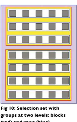
Fig 10: Selection set with groups at two levels: blocks (red) and rows (blue)
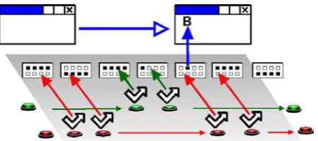
Group scan
In a group scan (see ig 10) the whole selection set is divided into groups of items and these are then individually highlighted (see the grouping section above). The user irsts selects a group, after which the individual items (or further groups) in that same group are scanned. The hierarchy of subgroups is scanned until one reaches the level of single items. When the item is selected the scan (usually) will be re-set to the top level again.
Obviously, groups can be any size or shape, however, a number of common forms exist:
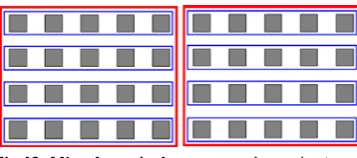
Row/Column - Column/Row Scan
Row/column and column/row scans (see ig 11) are special cases of the gen-eral group scan. They are set out in rectilinear grids where either the rows or columns are deined as the top level groups and the columns in the rows or the rows in the columns are the bottom level items. These set-ups have the advantage of being easily automated and are widely used in the UK.
Mixed Row/Column and Group Scan
Some systems employ a mixture of group and row-column scanning – for example, a rectilinear grid can be initially split into two halves as super-groups and then inside these super super-groups there can be sub-super-groups with items arranged in rows and columns (see ig 12).
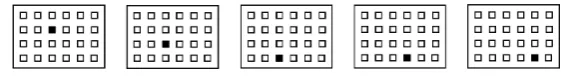
Progressive Segmenting Scan
Also known as ‘scan direct’, ‘quartering’, ‘halving’ etc… in this type of group scan the selection set is, with every selection, progressively split into two (or four). This provides a constant
number of selections for any item on a selection set of a given size (see ig 13).
[image:23.595.269.475.318.396.2]Fig 11: Row/column (left) and Column/row (right) scanning
Fig 12: Mixed row/column scanning: selection
set scanned by halves, rows then columns
Fig 13: Progressive segmented scanning:
64 items arranged in a hierarchy selected by quartering the selection set. Any item can be
chosen with three selections, choosing from four items each time
[image:23.595.275.454.492.571.2]Directed scan
Directed scans (ig 14 and 15) are used to emulate direct selection. The di-rection of the highlighter movement is controlled by switch operations. The scan movements required are Up, Down, Left and Right or combinations that give a 45-degree movement. The system has to decide which the next item in any of those directions is and send the highlight to that item. Selec-tions can then be made either with a switch press or by dwell selection.
The ‘natural’ setup for this would normally involve one switch operation per direction, however fewer switches can be used, eg using Right and Down only and ensuring the scan loops back to the start when it reaches the edge of the page; alternatively this could involve a rotating arrow indicating pos-sible directions of scan and a switch selection to implement that direction.
In general it is dificult, though not impossible, to apply a directed scan to anything other than a rectilinear grid. The start point for directed scan layouts would normally be set at the centre of the grid to give faster access to extreme items.
Highlighter movement control
As we have seen the highlighter must move from group to group or from item to item. The timing of this movement can be controlled either by the switch user or by the machine. Where the machine controls the scan it is es-sential to be able to customise the scan speed to suit the needs of the user.
There are a large different number of different ways of controlling the scan from one item/group to the next. The methods listed below are those in common usage, however they should not be considered to be the only available methods. For simplicity, in the next section, we will use the term item to encompass individual items and also groups, in addition the term ‘switch press’ is used to mean any switch action (further expanded upon in the switch actions section below).
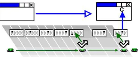
Autoscan
[image:24.595.79.364.189.227.2]With this scan method the device automatically progresses the highlight and the user presses a switch to select an item or group of items (see ig 16). The highlight starts at the irst item in the selection set and scans the items in order. Once the last item has been scanned the scan repeats from the irst item. When the switch is activated the currently highlighted item is selected. Autoscan generally requires a single switch.
Fig 14: Directional scan: An example of a directional scan pattern
[image:24.595.76.369.316.359.2]and a set of directional switches (these could be in a switched joystick)
Fig 15: Rotational, directed scan: For one or two switches
control and selection
[image:24.595.300.533.662.760.2]User scan
With this scan method the machine progresses the highlight only whilst the user is activating the switch (see ig 17). User scan generally requires a single switch. In this case the scan does not start until a switch press is de-tected. The machine then progresses the highlight at a predetermined rate (as in autoscan) until the user releases the switch.
With a single switch the currently highlighted item is selected on switch release or after a dwell time. With two switches the second switch is used to activate the currently highlighted item and the irst used to progress the scan.
Critical overscan
This scan control is devised to give a rapid access to items in a large selec-tion set without the complicaselec-tions of subsets. The machine controls the progression of the highlight which moves initially very quickly, the user then presses the switch to slow the scan and then select an item.
The highlight progresses as in Autoscan but at a signiicantly faster rate than the user’s Autoscan rate. The user presses the switch at about the time when the highlight is on the desired item - however because of the scan speed the highlight will probably have progressed past this point. The highlight then retraces the items at the normal rate and the user activates the switch to select the desired item (see ig 17).
One possible problem with critical overscan is caused if this irst switch is pressed too soon and the highlighter scans backwards away from the item the user wants. This can be ameliorated through appropriate setting of the scan, for example re-starting the fast forward scan after a certain number of slow reverse scans.
[image:25.595.226.463.174.276.2]control and selection
Fig 17: Userscan
[image:25.595.223.455.443.540.2]Step scan
In step scan the user controls the movement of the highlight and the selec-tion of the items (see ig 19). Step scan generally uses two switches.
Two switch use: pressing the irst switch progresses the highlight by one item, the second switch is then used to select the highlighted item.
One switch use (see ig 20): pressing the switch causes the highlight to progress by one item, the item is selected either through dwell select or another method (see the ‘selection’ section below).
Step scan switch alternation (swap switch)
In the case of step scanning with two switches it may be desirable to alter-nate the function of the switches (see ig 21).
When the switch function is alternated this means that when a selec-tion has been made with a particular switch its funcselec-tion swaps so that it becomes the switch which advances the highlighter. The other switch then takes on the role of selecting. After the next selection the roles reverse again. Alternating the switches may distribute the pattern of switch presses more evenly between the two switches.
[image:26.595.115.362.170.278.2]control and selection
[image:26.595.114.326.339.443.2]Fig 19: Step scan (two switch
Fig 20: Step scan (one switch use)
[image:26.595.117.343.519.619.2]Manipulating the highlighter
movement
As well as the alternative methods of moving the highlight, as listed above, it is possible to further manipulate the control of the highlighter movement.
Auto – restart, starting and restarting
After selecting an item the highlight can be restarted by either continuing from the position of the last item selected, or by starting from the initial item again.
Starting and restarting the scan, can either be automatic (the machine restarts the scan) or manual (wait for the user to press the switch to start). Obviously this only applies for scanning methods where the machine progresses the scan highlight.
It may also be required to restart more complex scans after a given number of passes (for example to control selection errors in critical overscan - where after two slow backward passes (say) the scan restarts to move forward).
With scans where the highlight is moved by the machine, it may be benei-cial for the system to highlight the irst item for a longer period than the other items.
Repeating items
On some occasions a user will want to be able to repeat the item that they have just selected (for example, channel up on a TV control). In general this is easier with two switches but should also be considered for other scan-ning methods.
Dealing with errors
The cost of the errors for switch uses is much greater than for other people since it takes more time and effort to correct wrong selections. There are a number of methods of correcting errors:
Error items:
‘backspace’ – this will undo the last character;
‘undo’/’redo’ – this should undo/redo the last ‘operation’
‘back’ – this is speciic to groups and pages and will reverse the last group/page change
Scan errors:
Errors in switch selections may not trigger an output, without a method of correcting a scan error the user is required to make an inappropriate selec-tion and then undo that selecselec-tion (a very costly process). Scan errors can be overcome in a range of ways:
Empty items – to allow users to select an item that does not result in an output and resets the scan
•
•
•
•
Cancel scan option – some systems have a speciic method for ‘offer-ing’ a scan cancellation – for example highlighting all the items in the current group.
Switch manipulation – it is possible to use a speciic type of switch ac-tivation (eg a long hold) to cancel the scan. See the ‘selection’ section below.
Selection
The simplest selection process is where any currently highlighted item is selected by a switch action. In autoscan processes this will be the only switch action. In addition to these ‘standard’ methods of selection there are a number of other options, described below.
Dwell selection
To select a highlighted item with this method, the user simply waits for a speciied time (see ig 21).
For example, with a ‘User Scan’, the user may progress the highlight to the desired item us-ing the switch, once on the desired item the user will wait – the item will be activated after the ‘dwell time’ has expired.
This method is not appropriate with some scan methods, for example Autoscan, since there is no opportunity to dwell!
This method is also used with other alternative access devices (described earlier) such as head pointers.
Switch encoded selection
In some senses, all types of (switch) access involve ‘encoding’ – you are sending information into the computer based on a ‘pattern’ of switch press-es. As well as the methods described above there are other, more direct, methods of encoding.
Combinatorial Encoding:
Given two switches there are four possible combinations of switch states, off/off, off/on, on/off, on/on, with three switches there are eight combina-tions et. The ‘chording’ keyboards that court typists use between ive and ten keys and allow the whole alphabet to be produced. You also use combi-natorial encoding everyday when you press the ‘SHIFT’ key.
Combinatorial encoding can offer speed advantages (as seen by the court-typist scenario), but have other drawbacks.
With respect to switches, combining switches can be used for occasional ‘power functions’ (e.g. cancel/delete etc), to switch between modes (e.g. Environmental Control and communication) or other functions.
•
•
[image:28.595.269.520.350.467.2]control and selection
It is also possible to use this method with some scanning methods, particu-larly the ‘Quartering/Halving’ methods – where combinations of keys select indicated groups/items.
Time Encoded Selection
Switches may also be used in sequence – the classic example of this is Morcode. With switch sequences the number of items that can be se-lected depends on the number of switch sequences allowed.
The selection is indicated by the number and/or timing of the key presses – think about the double click on a mouse, this is a time-encoded selection!
Time codes included Morse code6, both standard and two switch tapping systems. Examples of this type of system are included in some keyboard emulators and communication aids.
Either the relative or absolute lengths and sequences of switch presses can be monitored, for example: a long press is sometimes used to cancel a scan – monitoring the absolute length of the press; whereas morse code moni-tors the relative length of the dots and dashes.
Switch actions
Usually it is the change of state of the switch from on to off, or from off to on, which causes the system to respond. The switch action from off to on is called the leading edge, (positive) and the action from on to offer is called the trailing edge (negative).
In all the descriptions above we have assumed that it is the leading edge which the computer response to. This is called ‘press’. If the computer responds to the trailing edge this is ‘release’. It can be useful in some situ-ations to give users the choice as to whether press or release triggers the system.
There are, however, some instances where events are not edge triggered, for example: in User Scan the system responds to both edges; repeating ac-tions with some systems is enabled by holding the switch down.
Type ahead
Type ahead is caused when presses are made as the programme is car-rying out a slow process. Actions are stored in a buffer and fed to the programme as soon as the programme is ready. This can be useful, or a nuisance.
Numbers of switches
The number of switches is a key determining factor in switch access, but actually, it is mainly a by-product of a number of other decisions (i.e. those detailed above).
The table below shows the common setups for different numbers of switch-es - it should be noted that this is by no way the only way of doing things. For example, adding half switches or combinatorial encoding could radically alter a user’s switching setup.
Table 1: Common scanning modes for different numbers of switches
No. of Switches
Common scan or selec-tion modes
Other scan or selection modes
1 Auto Scan
User Scan
Step Scan with Dwell Select
Halving with Dwell Select
Critical Overscan
Encoding (Morse)
2 Step Scan
User Scan
Autoscan
Halving/Quartering
Time Encoding - Two Switch
Morse
Directed scan with Dwell select
3 Auto Scan
Step Scan
User Scan
All with repeat or reset on the third switch
Directed Scan
Halving/Quartering
Encoding with Quartering
4 Directed scan – Dwell Select
Directed scan – Switch select
Combinatorial Encoding (e.g. Chording)
‘Direct’ Quartering
5 Directed scan - all directions & select
Combinatorial Encoding (e.g. Chording)
Multiple Encoding
Directed Scan
Direct access
Keyboard
Combinatorial Encoding (e.g. Chording)
Half Switches
Adds an extra functionality to any of the above for infrequent use.
Half switches
An extra switch is often added to scanning systems where an infrequent action or ‘power function’ can be assigned to it. Even switch users with poor control can sometimes utilise this extra ‘Half switch’ to do things like changing between computer control and wheelchair driving. A half switch would always be used to achieve a single function, i.e. it would not be used as part of the scanning process.
In addition to the possible different scan methods described in the previous sections, a range of other parameters exist with respect to the timing of the scanning process. Most of these timing parameters apply to Automatic scan methods although a few of them will also apply to scanning movements controlled by the user.
The various parameters are described below; again these are not neces-sarily exhaustive. Many systems use essentially random measures of time (based on the system clock) – this causes variability across systems. There is a sensible and well established unit of time that could be used - the second (millisecond)!
Timing parameters
Scan time
This is the time it takes for the highlight to move from one object (group or item) to the next. Where appropriate the switch user should be able to change the speed themselves. If this option is provided there must be a mechanism by which the user can escape from a situation where the rate is set to fast! A short trial process would be a way of achieving this.
Initial scan time
When the scan starts at the top of the selection set it is often useful to some users to have an extra delay before the scan moves to the irst item. A percentage or multiplying factor (of the scan time), or a discreet time is probably the best way to set this parameter.
Scan pause
It can be beneicial to allow users to collect their thoughts before the next stage of the scan. A delay between pages/groups may aid some users in this. This only applies to scan methods where the highlighter is progressed by the machine and is hierarchical (i.e. has groups/pages). Again, a percent-age or multiplying factor (of the scan time) or discreet time is probably the best way to set this parameter.
Timing and Input
Filtering
Dwell time
This is the time used for some control methods to action the selection of a group or item when a switch action to carry this out is not possible. If the highlight is stationary for longer than this time, then a selection is made.
Repeat functions
Some of the items selected from sets will be of greater use if they can be repeated without having to be reselected. Three parameters are needed to control this function - auto-repeat, repeat delay and repeat time. It is par-ticularly useful to provide auto-repeat on for example arrow keys or mouse movements. Note the subtle difference between scan time and repeat time.
Repeat delay
This is the time for which a switch state must be held before the repeat starts (see ig 23). The users may need some time to transfer their attention to the repeated action or time to avoid errors. The repeat delay, similar to the repeat delay on the keyboard, is a period of time which must pass before the irst repeat action happens.
Repeat time
This is the time between successive repeats once the item has started to repeat. In some cases it may be possible for the repeat time to accelerate. For example, the function might irst repeat slowly and then more quickly (e.g. with a mouse movement). This could use the same time as the scan time but in practice it is better to have a separate time. It is again similar to the setting in Window’s keyboard accessibility options.
Auto-repeat
With the auto-repeat on, once an action has been selected, the output will be repeated until another press/release event is detected. With the auto-repeat off, only one output will be sent for each switch action. The auto-repeat happens at the rate set by the repeat delay/repeat rate setting. An example of this might be a volume up item on an Environmental Control, keyboard actions (e.g. PgUp) or mouse actions (e.g. move mouse right).
Input filtering
This is the process of removing all unwanted switch actions. These may have a number of causes:
Switch bounce. When mechanical switches are pressed or released there is a natural springing of the mechanism and this can cause some additional ‘phantom’ activations. Corroded contacts can also cause the same problems.
•
[image:33.595.70.281.283.393.2]timing and input filtering
Involuntary actions by the user (ataxia or tremor etc) may result in ac-cidental switch presses in close succession. This could be just before, or just after the intended press.
When there is any type of input iltering it can be particularly important for some users that clear feedback is provided to demonstrate whether a switch action has both been recognised and accepted.
Another list of the different types of input iltering is provided below, this list has the same health warning of all the others – “there are other ways of doing this”:
Debounce time
This is the time after a switch press before a switch re-lease will be recognised by the system (see ig 24). Thus the system will not respond to the rapid changes fol-lowing a press or release action. This helps to overcome switch bounce caused by imperfect electrical contacts and can help with some problems of tremor.
Acceptance time
The acceptance time is the time the switch must be held down for before the system recognises the switch action (see ig 25). This can also apply (less commonly) to switch releases. This can be helpful for some people with tremors or other disabilities that may either cause them to make accidental (but brief) switch presses. It may also be relevant when a user ‘drags’ over switches and then ‘rests’ on the desired switch.
Post-acceptance time
This is the time after the last switch press after which the computer will accept another switch press (see ig 26). There is a subtle, but important, difference between this and the debounce time where the switch release is involved! This is intended to ilter out some tremor problems. Switch events should not be looked for by the computer until a given time after the last switch event has been accepted. This can often be quite long to take
account of the user making further involuntary actions after the intended switch press. In such circumstances it is likely that setting this parameter will make setting up a de-bounce delay unnecessary.
•
[image:34.595.58.524.247.650.2]timing and input filtering
Fig 24: Debounce time
Fig 25: Acceptance time
It is hoped that this document has provided a clear and consistent descrip-tion of the switching process. As stated we have deliberately not made any speciic recommendations within this document – this is not because we have nothing to say on the subject – but because we believe this document is the foundation for any further discussion, research and evidence on the topic of switching and scanning.
Hopefully this document will deine a standard vocabulary, terminology and parameters for switch access and scanning. Ultimately we hope it will lead to more and better switching systems that users can move between easily.
We welcome and encourage comments and suggestions on this document – we hope that it will evolve and improve with suggestions before releasing it as a proposed standards document. You may wish to place and develop suggestions on the Assistech WIKI (http://tinyurl.com/n4k96) or email one of the authors:
David Colven
Simon Judge
Conclusions
Switches are used with a large number of Assistive Technology devices. These devices can be roughly grouped into two – dedicated proprietary devices and computer based devices. Most devices are microprocessor or computer based, but proprietary devices will be dedicated to a single or small number, of tasks. Proprietary devices will normally have switch access incorporated into the device and will allow you to conigure the scanning through an interface on the device.
To plug switches into non-proprietary computer based devices you need a connector (switch interface) and software that will do something useful with the switch inputs. Luckily, with the use of USB, plugging switches into a computer has become very easy. The information below is provided as a full reference on this topic however.
Switch software
The full range of Assistive Technology software is beyond the scope of this document, however ‘switch driving’ software is of note. This software allows switches (connected via the switch interfaces listed below) to be ‘mapped’ to any key or mouse function. This enables the switches to be used with Assistive Technology software that does not have an inbuilt switch driver. It also allows the switches to be used with standard software such as PowerPoint (indeed a large number of switch accessible PowerPoint resources exist within the SEN Assistive Technology community). Some switch drivers will detect the currently used application and automatically conigure the switches appropriately. USBKeys (www.switchindex.com/usb-keys.htm) and the Sensory Switch Driver (www.sensorysoftware.com) are examples of switch driver software.
Ports
Switches are connected to a computer via a port – for example USB, Serial etc. Switches can be connected directly to a port (rare these days) but are usually connected via a ‘switch interface’. The switch is normally plugged into the switch interface using a standard connector.
Use of switches was pioneered in British Education system mainly on BBC and Apple II computers. The BBC had an 8 channel port called the user
Appendix 1:
Connecting Switches
to a Computer
port which allowed up to eight switches to be connected at once. Switch interfaces are standardising on using USB, however the number of switch inputs seems to be decreasing. See Appendix 4 for a table of ports - operat-ing systems and interfaces.
Switch interfaces
It is important that switch controlled systems should allow connection of switches through the full range of available ports and interfaces. Users and their facilitators do not want to be continually changing connections as dif-ferent software is used. Unfortunately there is no agreed universal standard – although the ease of use of USB interfaces is increasingly making these the standard. Common interfaces are:
USB
It is possible to get a range of different USB switch connectors – these emu-late a games port (ire buttons). For example: JoyCable, JoyBox, CrickBox, AnyCom etc...
Keyboard
Using the keyboard as a switch input designates some of the keys as switch inputs and a keyboard-switch interface would allow switches to activate these keys. Using the keyboard has the advantage of making reading switches easy. The disadvantage is that the designated keys may not be used by a helper to assist the switch user. Don Johnston and Inclusive Tech-nology are among the suppliers of keyboard interfaces. Overlay keyboards could also be used as a switch.
Parallel port
The Words+ system uses the printer port for multiple switch input but includes a ‘dongle’ which locks out other software interfacing. So far they have resisted giving any information on how to read the switch connec-tions. The parallel printer port is now being phased on portable devices.
Older interfaces
The ‘Linx box’, related to the UK Concept Keyboard, sending coded signals into a comms port (up to 4). This is no longer available.
Serial (dead) mouse as used by Switch Access to Windows (SAW) users and some other software. This has complications over clashes with proper mice but can be simple to set up.
Serial Port using interconnections of the handshake line on a comms port, for up to 4 or more switches but commonly only uses 2 inputs. The Flipper type switch interface can be used by Clicker 4, Widget Soft-ware and SEMERC (SEMERC II)
•
•
•
Appendix 2:
Switch Control
of Systems
No. of
Switches Control Other names Comment Parameters Priority
1 Autoscan Probably the most popular and most eficient system for users
with good timing
Scan time Start delay Autostart Autorepeat Repeat delay Repeat time Essential
1 User scan Reverse scan For those whose release is more controlled than their press Scan time Start delay Autorepeat Repeat delay Repeat time High
1 Critical overscan autoscan
A way of giving users with poorer control of timing faster access to larger grids with least effort. Scan time Start delay Autostart Autorepeat Repeat delay Repeat time Low
1 Critical overscan user scan
A way of giving users with poorer control of timing faster access to larger grids with least effort. Scan time Start delay Autorepeat Repeat delay Repeat time Low
1 Single step scan Gives control to the use and takes away the pressure for the need to ‘get it right’
Autorepeat Dwell time Repeat delay Repeat time
Low
1 Directed A way for single switch users to control their own movement
over a large number of options
at one level
Scan time Start delay Autostart Autorepeat Repeat delay Repeat time Lowest
[image:40.595.67.312.84.213.2]appendix 2: switch control of systems
No. of
Switches Control Other names Comment Parameters Priority
2 Autoscan Not frequently used but pos
-sibly should be considered more frequently. It can speed
up access for two switch users
and can be a bridge to single
switch usage. Scan time Start delay Autostart Autorepeat Swap Repeat delay Repeat time High
2 User scan Reverse
Inverse
Similar to autoscan but giving
more control to the user.
Scan time Start delay Autorepeat Swap Dwell time Repeat delay Repeat time Essential
2 Single step scan The most frequently used two
switch scanning method. Gives complete control to the user.
Autorepeat Swap Dwell time Repeat delay Repeat time Essential
1 Morse - one
switch
Can be user-deined codes Dwell time Low
2 Morse - two
switch
Involves timing even with two switches
Dwell time Low
3 Two switch directed scan
The third switch selects Scan time Start delay Autostart Autorepeat Repeat delay Repeat time Low
4 Joystick directed
Scan (dwell select)
For those who ind accessing a
faster switch dificult
Scan time Start delay Autorepeat Dwell time Repeat delay Repeat time High
5 Joystick directed scan and select
Gives more control to the joystick user who can access a faster switch. Scan time Start delay Autorepeat Repeat delay Repeat time High
N N-way Encoding
(sequential)
This was popular among some advanced users with the
Mac-Apple Switch word processor
and It can be very rapid.
Dwell time Low
N N- way encoding
(Simultaneous)
Chord keyboards Not applicable to Scanning
Systems
Repeat delay Repeat time
N/A
Appendix 3:
Summary of
Terminology
Term
Deinition
Other equivalent
terms
Acceptance
The registration by the system that a valid switch
press
has been made following switch iltering.
Hold down time
Accepted
The registration by the system that a valid switch
press
has been made following switch iltering.
Auto Restart
When a scanning system resets the current
high-light back to the start position of the scan rather
than carrying on to the next item.
Control
The way in which switch actions control the way
a scan moves.
Critical
Over-scan
A system of scanning where the scan initially
moves very fast and then does a slow reverse
scan to enable speed with accurate selection
Dwell Select
The process of having items in a selection set
chosen by doing nothing or holding a switch
down for a set time.
Debounce
A way of removing unwanted switch signals
caused by poor electrical contacts in the switch
itself
Tremor delay
Event
The signal that something has happened such as
switch
down (pressed) or switch up (released)
Facilitator
A helper who aids the user and may adjust the
user’s system.
Filtering
The process of eliminating incorrect switch
ac-tions caused by the user’
s involuntary actions.
Grid
A rectilinear selection set of items arranged in
rows and columns.
Scanning may be carried out
by simple
scanning, row/column or column/row.
Group
A sub-set
of items grouped together so that the
groups
can be scanned and then chosen by the
process of selection
to then be scanned internally.
This is a way of deining the hierarchy
of the
selection set.
Row, Column
[image:42.595.67.275.85.218.2]appendix 3: summary of terminology
Term
Deinition
Other equivalent
terms
Highlight
The indicator used to show that any item or
group is available for selection
at that time.
Item
A single
selectable element of a selection
set. The
item that contains the text or command to be
acted upon.
Method
The way in which a scan
moves by the process of
highlighting across a selection set so that choices
can be made.
Post
accept-ance delay
A time following an event that has been accepted
by the controlled device in which all further
events are ignored.
Tremor delay
Press
The ‘switch down’ event
Release
The ‘switch up’ event
Scan
The movement of the highlight from one item to
the next. This will either happen at pre-set times
or following a scan switch press
being accepted.
Selection Set
A complete set of items and/or groups of items
that are presented to the user for selection at any
one time. Some of the groups or items may be
hidden until required.
Grid, On-screen
keyboard
Scan Reset
See Auto Restart
Toggle
A switch or other control that is activated (e.g.
pressed) once for on, then again for off.
User Scan
A scan which proceeds as long as a switch is help
down.
Inverse scan
Reverse scan
Device
Description
Tracker Balls or
Trackball
A mouse pointer controller that uses a ball to move the
mouse pointer when the ball is rolled in a given direction.
This is in fact the irst type of computer pointer controller
dating back to the mid-1960’s.
Touchscreen
A way of directly moving the pointer and clicking by touch
-ing a screen. There are three main types:
Resistive; can be operated with the lat of a inger.
Capacitive; needs a sharp point to move the pointer such
as a inger nail.
Active Pen; needs a compatible electronic pen to move the
pointer.
[image:43.595.142.531.83.509.2]appendix 3: summary of terminology
Device
Description
Head Pointers
Systems which interpret head movement and move the
screen pointer appropriately.
Assistive Technology
Any technology that can enable someone to overcome a
handicap imposed by their environment.
Bandwidth
The amount of information that can be passed though
any given channel. The more information the higher the
bandwidth.
Joysticks:
Devices that can control computer screen pointers, games,
wheelchairs (or aeroplanes!) by moving a gimballed stick in
from its rest position.
Analogue Joystick
The cursor/selection speed varies with delection of the
joystick. The joysticks usually have unlimited two
dimen-sional movement. These devices can be used to move the
mouse pointer as a mouse emulator or as a games device.
Switched Joystick
The cursor/selection speed is constant when the stick is
pressed in a limited number of directions – usually 4 or 8.
The system being controlled can act continuously or with a
single action each time the joystick is moved.
Eye Pointers
Systems that translated movement of a person’s eye into
screen pointer movement.
On-Screen Keyboards
Virtual keyboards that appear on computer screens and
have the same function of physical keyboards. Some can be
accessed with the screen pointer and others with switches
or both
Layered Hierarchy
A way of arranging large numbers of items in groups and
sub-groups so that they can be accessed faster or with less
effort.
3.5mm jack connectors
The current ‘standard’ for switch connection the same
size as Walkman headphone connectors. In the USA this
is 5/8” which is almost identical. These are usually mono
(single channel) connectors with two contacts but two
switches can be connected through stereo jacks with three
connectors.
USB
The Universal Serial Part now itted to all computers, both
PC and Mac. Devices of many kinds can be connected to
USB ports. Most AT devices imitate Mice, Keyboards or
Games controller ire buttons.
Interface PC/ Mac Port No I/P Manufacturers /
Suppliers Web Site
Compatible
Software (eg) Notes
Serial Switch Box
PC Serial 2 SEMERC,
Inclusive Technol -ogy,
Crick Software, Widget
www.inclusive.co.uk
Clicker 4, The Grid, SAW
Now obsolete as
many computers do not have standard RS232 serial ports particularly laptops.
USB Mouser 4 PC USB mouse 3 SEMERC,
Inclusive Technology www.inclusive.co.uk
Any that uses
mouse button
clicks
Allows switches to
be connected to the
left, middle and right
mouse buttons PS/2 Mouser PC PS/2 mouse 2 SEMERC,
Inclusive Technology www.inclusive.co.uk
Any that uses
mouse button
clicks
As above but now obsolete as PS/2
interfaces are withdrawn from new computers particu-larly laptops.
Switch Interface
Pro
PC &
Mac PS/2 or ADB
Keyboard
5 Don Johnston www.donjohnston.com Any software that can use a
keyboard key
input as a switch.
Limited to a few
key combinations controlled by the keyboard lock keys Switch Interface Pro 5 PC & Mac USB Key-board
5 Don Johnston www.donjohnston.com Any software that can use a
keyboard key
input as a switch.
Limited to a few key
combinations con
-trolled by the state of switches on the box
itself.
iMate Mac USB-to-ADB adapter
Don Johnston,
Grifin Technolog, Inc
www.donjohnston.com As above Allows you to connect any ADB peripheral to
newer USB-equipped Macintosh comput -ers. Discover:Kenx, Discover:Switch, Discover:Board or
Switch Interface Pro.
Quizworks PC &
Mac USB Key-board 5 Inclusive Technology www.inclusive.co.uk Any software that can use a
keyboard key
input as a switch.
Allows switches to send space, enter,
tab, esc, backspace,
up arrow, down ar-row, left arar-row, right
arrow, 1, 2, 3, 4, 0
and click.
SwitchBox PC PS/2 8 Inclusive Technology www.inclusive.co.uk Any software that can use a
keyboard key
input as a switch.