1 INTRODUCTION
Many infrastructures suffer from corrosion problems resulting to its reduced service life. This problem has been severely affecting many bridges especially in the coastal areas of Japan. Maintenance of these in-frastructures has increased dramatically hence new materials have been developed to overcome this problem. FRP composite materials have excellent properties which could be advantageous in harsh en-vironmental conditions but its high cost has limited its use. A hybrid FRP composite for bridge girder application is now being developed. The innovative feature of this girder optimizes the combined use carbon fibre reinforced polymer (CFRP) and glass fibre reinforced polymer (GFRP) for maximum structural performance while minimizing production cost (Mutsuyoshi et al., 2007). It is believed that this material can be competitive with other conventional materials in the near future when life cycle cost is taken into account (Nishizaki et al., 2006). In view of this, several studies have been undertaken to ad-vance this material for civil infrastructure use.
FRP composites are not covered by material stan-dards and information on its material properties is not well known and documented. According to Bank (2006), it is generally preferred to determine the ma-terial properties of FRP composites experimentally and not rely only on theoretical models. Thus, tests of coupons were initially conducted in order to de-termine the effective mechanical properties
represen-tative of the hybrid FRP composite section. Test method from accepted or existing test standards for FRP composites were adapted and modified to work with thick laminates of the hybrid FRP composites.
The design of an efficient connection represents one of the major challenges in the development of composite structures (Magness, 1991). The capacity of a structure is often limited by the capacity of its connection thus a reliable jointing system should be determined in order to use the hybrid FRP girder for practical applications. In this study, fundamental in-vestigation using coupon and full-size specimens was conducted to characterize the strength and be-havior of the hybrid FRP composites with bolted joints. The parameters investigated were the effect of applied bolt torque and the contribution of epoxy adhesive on the load capacity and failure mode of bolted joints. Analytical evaluation of the joint strength using the effective mechanical properties obtained from the coupon tests was conducted and compared with the experimental results.
2 MATERIAL PROPERTIES OF HYBRID FRP COMPOSITES
2.1 Test of hybrid FRP coupons
A total of 30 tensile and 36 compressive tests using coupon specimens cut from laboratory size panels
Mechanical behavior of hybrid FRP composites with bolted joints
A.C. Manalo, H. Mutsuyoshi & S. Asamoto
Department of Civil and Environmental Engineering, Saitama University, Saitama, Japan
T. Aravinthan
Centre of Excellence in Engineered Fibre Composites, University of Southern Queensland, Toowoomba, Queensland, Australia
H. Matsui
Toray Industries, Incorporated, Tokyo, Japan
were conducted to determine the effective mechani-cal properties of hybrid FRP composites. Steel pipes filled with high strength, low viscosity epoxy was used as anchorage of the hybrid FRP coupons under tensile loading. The FRP coupons were tabbed over 30 mm at each end with GFRP laminates or inserted into steel pipes filled with epoxy for the compressive strength test to prevent end-crushing. The specimens for the compressive modulus test were identical to the strength test specimens without the tabs.
The tensile test was conducted in accordance with the ASTM D3916 and ACI 440 specifications as shown in Figure 1a. On the other hand, the hybrid FRP coupons were tested for strength and modulus under compressive load using the test fixture fabri-cated based on ASTM D3410-87 as shown sche-matically in Figure 1b.
[image:2.612.62.289.264.405.2]
a. tensile test b. compressive test Figure 1. Coupon test set-up and instrumentation
[image:2.612.316.556.279.403.2]2.2 Effective mechanical properties
Table 1 shows the effective mechanical properties of the hybrid FRP laminates based on the coupon test. The effective elastic modulus in the longitudinal (E11) and transverse (E22) directions was determined
from the linear portion of the stress-strain curve be-tween 1000 and 3000 microstrains. The strength was calculated from the maximum load and the average width and thickness of the coupon specimens. Pois-son’s ratio was computed as the ratio of the lateral strain to that of the axial strain. These mechanical properties were used in the prediction of the behav-ior of the bolted joints for hybrid FRP composites.
Table 1. Effective mechanical properties of hybrid FRP lami-nates.
Parame-ters Units
Nota-tions Tension Compression
Flange Web Flange Web
Modulus N/mm2 E11 50,670 15,300 48,350 19,780
N/mm2 E22 13,400 15,300 16,280 19,780
Poisson’s mm/mm υ12 0.235 0.27 0.269 0.297
ratio mm/mm υ21 0.182 0.27 0.046 0.297
Maximum N/mm2 σ
11 884 185 347 203
stress N/mm2 σ
22 171 185 177 203 Failure
strain % 1.4 1.4 0.4 1.0
3 COUPON TEST OF BOLTED JOINTS
3.1 Experimental program
A double-lap bolted joint with 2, 4 and 8 bolts was considered as the experimental model. This corre-sponds to the specimens 2b, 4b and 8b respectively. Twenty-seven coupons representing the flanges of the hybrid FRP composite girder were tested up to failure. The description of the specimens for coupon test of bolted joints is listed in Table 2. All of the specimens were prepared based on the minimum recommended geometric configurations for bolted lap joints as listed in Bank (2006). Stainless steel bolts with a nominal diameter of 10 mm and yield strength of 600 MPa were used. The torque was ap-plied to the bolts using a presetting torque wrench at 10, 15, 20 and 25 N-m.
Table 2. Specimen description coupon test of bolted joints.
Specimen name
Number of specimens
Number of bolts
Applied bolt torque
Epoxy adhesives
2b-10t-wo 3 2 10 without
2b-15t-wo 5 2 15 without
2b-20t-wo 5 2 20 without
2b-25t-wo 4 2 25 without
4b-20t-wo 2 4 20 without
8b-20t-wo 2 8 20 without
8b-25t-wo 2 8 25 without
4b-20t-e 2 4 20 with
[image:2.612.317.553.574.732.2]8b-20t-e 2 8 20 with
Figure 2 shows the geometrical configuration of the 2-bolted joint tested in this study. The specimen with epoxy adhesives and those without had the same configuration. The experimental set-up is illustrated in Figure 3. Angular aluminum bars were attached on both sides of the FRP laminate and the splice plate. Linear variable differential transducers (LVDT) and draw-wire displacement transducers were then provided on these aluminum bars in order to measure the relative displacement between the FRP laminate and the splice plate.
a. Side view
[image:2.612.56.294.634.745.2]b. Top view
Figure 2. Double lap bonded/bolted joint (2-bolted joints)
P
metal grip
FRP coupon
strain gauges
metal grip
top loading platen
cap head fixing bolts FRP coupon
cap head strain gauges
load guide
bottom loading platen
P
Splice plate (80x9x232)
Filled plate (80x13.5x170)
Steel bolts, 10 mm φ
FRP laminate
2- Aluminum plate (80x2x170)
120 mm 82 mm 30 50 mm 50 mm 120 mm
170 mm 32 30 50 mm 170 mm
20
40
0 100 200 300 400 500
0 1 2 3 4 5 6 7 8
Displace me nt (mm)
L
o
a
d
(
K
N
)
4b-20t-w o (206) 4b-20t-e (209) 8b-20t-w o (419) 8b-20t-e (408)
0 20 40 60 80 100 120
0 1 2 3 4 5 6 7 8
Displacement (mm)
L
o
a
d
(
K
N
)
2b-10t-w o (89.1)
2b-15t-w o (91.2)
2b-20t-w o (94.1)
2b-25t-w o (98.8)
0 100 200 300 400 500
0 1 2 3 4 5 6 7 8
Displacement (mm)
L
o
a
d
(
K
N
)
[image:3.612.311.559.36.167.2]8b-20t-w o-1 8b-20t-w o-2 8b-25t-w o-1 8b-25t-w o-2
Figure 3. Schematic diagram of the bolted joint test set-up
3.2 Effect of applied bolt toque on joint strength
The load-displacement behavior shown in Figure 4 indicated that with the different levels of applied bolt torque there was very little friction resistance since slipping of the joints occurred at the initial loading stage. The behavior is almost linear indicating that the bolts slipped into bearing with the FRP lami-nates. This linear behavior occurred up to around 70 kN with the displacement between 2 and 3 mm. The curve became non-linear until final failure. This could be due to the initiation of bearing failure in the FRP combined with bending of the bolts. In the range of the investigated torques, it was observed that the capacity of bolted joints increased slightly with increasing torque. The joints with 25 N-m tightening torque has the highest average load capac-ity while the specimen with 10 N-m has the lowest.
The behavior of 8-bolted specimens using 20 and 25 N-m torque was further examined in order to de-termine the amount of applied bolt torque to be used in the succeeding tests. Figure 5 shows similar load-displacement behavior for all tested specimens. Slipping of the joints occurred at initial loading stage. The displacement increased linearly with load up to 300 kN then becoming non-linear up to failure. However, the specimens with 20 N-m torque showed higher stiffness and failed at a slightly higher load. It was then concluded that an applied torque of 20 N-m is reasonable for hybrid FRP composites.
[image:3.612.69.281.42.177.2]Figure 4. Load-displacement of the joints at different levels of applied bolt torque
Figure 5. Load-displacement of 8-bolted joints at 20 and 25 N-m applied bolt torque
3.3 Contribution of epoxy adhesives
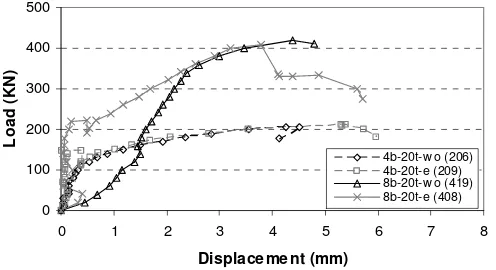
The contribution of epoxy adhesives on the strength and behavior of bolted joints for hybrid FRP com-posite was examined using specimens with 4 and 8-bolt configurations at 20 N-m tightening torque. The load-displacement relationship of specimens with and without epoxy adhesives is shown in Figure 6. The results showed that slipping of the bolted joints in specimens without epoxy occurred at a lower load. On the other hand, the bolting accompanied by adhesive bonding provided resistance against slip-ping between the splice plates and the FRP lami-nates. The debonding of the epoxy adhesives lead to an abrupt drop in load but the load again increased thereafter indicating that the applied load was trans-ferred to the bolts. The connection then behaved similar to the bolted joints without epoxy adhesives until final failure.
The 4b-20t specimens with and without epoxy failed at almost the same load and similar failure mode was observed on the FRP laminates. All of the 4b-20t specimens failed at an applied load of 205 kN. On the other hand, the 8b-20t specimens with epoxy failed at a slightly lower load compared to that without epoxy. The maximum load that the specimen without epoxy carried is 420 kN while the specimen with epoxy is only around 400 kN. The failure mode for both specimens was also different.
Figure 6. Load-displacement of joints with and without epoxy
P
metal grip
splice plate
FRP coupon specimen
displacement transducer
strain gauges
Aluminum angular bar
LVDT draw wire displacement
transducer
LVDT
[image:3.612.314.562.572.707.2] [image:3.612.53.302.583.719.2]-100 200 300 400 500
0 2 4 6 8 10
Number of bolts
L
o
a
d
c
a
p
a
c
it
y
(
K
N
)
2 bolt s 4 bolt s 8 bolt s Eq. 1 (bearing) Eq. 2 (bolt shear)
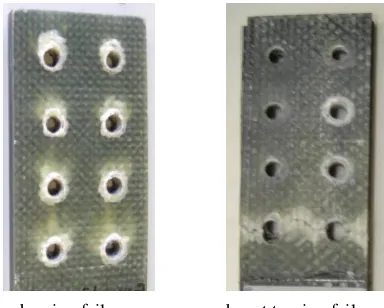
3.4 Failure mode
The splice plates were removed after every test to examine the damage on the FRP laminates. Figure 7a shows that the specimens without epoxy failed due to bearing of the FRP laminates in both the CFRP and the GFRP with initial signs of shearing out in the CFRP. Crushing of the composite material in the vicinity of the bolt-hole interface was ob-served. In the specimen with bolts and epoxy adhe-sives, failure was due to bearing and delamination between the CFRP and the GFRP (Figure 7b). The high energy released during the epoxy debonding might have caused the delamination. Net-tension failure was also observed in the GFRP after the final failure. This finding is similar to Duthinh (2000) where the laminates containing +45o GFRP plies showed low tensile strength and failed mostly in net-tension. However, the presence of unidirectional CFRP in the hybrid FRP composites prevented the sudden failure of the specimens.
a. bearing failure b. net tension failure Figure 7. Failure of the hybrid FRP composite with bolted joints with and without epoxy
3.5 Analytical evaluation
Theoretical mechanics-based equations were used to analyze the strength limits of the bolted connections. The load capacity due to bearing, Pb was calculated using Equation 1. According to Bank (2006), if the bearing strength of the FRP composites is not avail-able, the material compressive strength can be used for approximate calculation.
pl b b b nd t
P =σ (1) where σb = compressive strength of FRP; n = num-ber of bolts; db= diameter of bolts; and tpl = thick-ness of the laminate.
On the other hand, the load capacity of bolts in double shear, Pv is given as Equation 2. Shear strength was determined using the shear yield stress of the bolt, τb, which was approximated as 0.60fy, where fy is the yield strength of the bolt multiplied by the total cross-sectional area of the bolt shank.
b b
v A
P =2τ (2) and Ab was computed using the Equation 3.
) 4 / ( b2 b n d
A = π (3) Figure 8 shows the comparison between the load carrying capacity of the bolted joints obtained from the experimental investigation and the predicted val-ues using the theoretical equations. In view of the difficulty in determining the load in which failure of the bolted joints occurred, the maximum load carried by the specimen was used as the measure of the joint strength. The results showed that a good agreement was achieved between the values predicted using Equation 1 and the result of the experiment in the specimen with 2-bolted joints. However, a higher load was obtained in the actual test compared to the predicted values for the 4 and 8-bolted joints. Using the Equation 2, the estimated joint capacities based on the shear strength of the bolts are slightly higher than the experimental results for all the number of bolts. This result showed that the load carrying capacity of the hybrid FRP composites with bolted joints can be reliably designed based on the compressive strength properties of the materials determined from the test of coupon specimens.
[image:4.612.77.269.291.445.2]
Figure 8. Predicted and actual strength of bolted joints
4 FULL-SCALE TEST OF BOLTED JOINTS
4.1 Experimental program
[image:4.612.320.541.376.519.2]0 20 40 60 80 100 120
0 10 20 30 40 50 60
Displacem ent (m m )
L
o
a
d
(
K
N
)
FRP-9mm J-FRP J-FRP-epoxy
0 20 40 60 80 100 120
-6000 -4000 -2000 0 2000 4000 6000
Strain (microns)
L
o
a
d
(K
N
)
FRP-9 mm, T J-FRP, T J-FRP-epoxy, T FRP-9 mm,C J-FRP, C J-FRP-epoxy, C
[image:5.612.313.540.198.341.2]The beam was simply supported and tested under four-point loading as shown in Figure 9. The load was applied manually by hydraulic jack at third points through a spreader beam. Displacement trans-ducers were installed to measure the displacement and strain gauges were attached on the FRP girder to evaluate the strain during loading until final failure. Data logger was used to record the data with the load-deflection curve displayed during testing to monitor the beam behavior. A similar full-size beam without joints (FRP-9mm) was initially subjected to a four-point bending test to verify the difference in behavior of the hybrid FRP composite girder with and without joints.
Figure 9. Test set-up for full-size hybrid FRP girder with joints
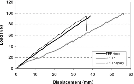
4.2 Load-displacement relationship
The load and midspan deflection relationship of FRP-9mm, J-FRP and J-FRP-epoxy under four-point loading test is shown in Figure 10. According to the result, specimen FRP-9mm behaves linear elastic up to failure. The beam failed at an applied load of 94.9 kN and a midspan deflection of 39.1 mm. The slope of the load-midspan deflection of J-FRP is the same with that of FRP-9mm only up to an applied load of 5 kN. With the continuous application of load, the beam showed a slight yet steady decrease in stiffness. This could be due to the slipping of the bolts and the gap provided between the beam end faces which allowed it to rotate. The specimen was loaded up to 97.9 kN and a midspan deflection of 56.3 mm was recorded. At this point, the test was stopped and the load was released. There was no sign of failure observed in the bolts and in the FRP laminates when the splice plates were detached. It was then concluded that if the test was continued, the specimen J-FRP might have carried a higher load before its final failure. Using the same speci-men, epoxy adhesives were provided in the bolted joints and the flexural behavior of this girder was examined under the same loading condition.
In the specimen with bolted and epoxy bonded joints, the load increases linearly with deflection
un-til final failure. The beam failed at an applied load of 93.9 kN with a midspan deflection of 36.9 mm. It is noteworthy that the stiffness of J-FRP-epoxy is slightly higher than that of FRP-9 mm even though the load levels are identical for the two specimens. The difference in observed stiffness can be attrib-uted to the delay of epoxy debonding and the con-tribution of the splice plates on the bending capacity of the beam. The epoxy filling the gap between the beam ends might have prevented it to rotate. This re-sult suggests that the use of combined bolts and ep-oxy adhesives provided a reliable connection method for hybrid FRP composites.
Figure 10. Load and midspan deflection of hybrid FRP with and without bolted joints
4.3 Load-strain relationship
Figure 11 shows the relationship between the load and strain of the top and bottom flanges at midspan section of the hybrid FRP girder with and without joints. Result showed that the strains in both tension and compression increased linearly with load for all specimens. An average maximum strain of 4,500 microns in tension and 4,600 in compression were measured for all specimens. It was observed that the failure in all specimens occurred at a compressive strain comparable with the recommended value of 4,000 microstrains in a maximum strain type failure criterion in the compressive flanges of hybrid FRP established from the test of coupons. However, the maximum tensile strains measured in all specimens were only 30% of the recommended failure strain.
Figure 11. Load and strain relationship hybrid FRP composite girder with and without bolted joints
3700 mm
350 FRP Girder
hydraulic jack
load cell
FRP Girder spreader beam
safety rig
1000 500
1000 350
Support block
Support block bolted joints
[image:5.612.60.290.228.380.2] [image:5.612.321.547.591.730.2]4.4 Failure mode
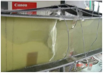
Figure 12 shows the failure mode of specimen FRP-9 mm. The mode of failure was the delamination be-tween the CFRP and the GFRP in the compression flange at the constant moment region followed by shear failure at the web.
[image:6.612.76.273.425.567.2]The specimen J-FRP exhibited large amount of deflection when the test was stopped. No signs of failure in the bolts and the bolt holes of the specimen was seen when the splice plates were removed. For specimen J-FRP-epoxy, failure occurred at the com-pression flange between the loading point and the splice plate. During the application of the load, a loud sound was heard following a sharp increase in beam deflection. It was found that the beam failed due to the delamination between the stiff composites of the combined CFRP and GFRP and the compara-tively soft GFRP as shown in Figure 13. Visual in-spection showed no sign of debonding failure in the epoxy adhesives. This type of failure was expected since the beam was designed to fail outside the joints. Accordingly, if the joint is sufficiently de-signed, the loading capacity of the hybrid FRP girder with and without joints is governed by the bonding strength at the interface of the CFRP and GFRP. It is therefore recommended that the hybrid FRP compos-ites not be subjected to high compressive stress or further enhancement is needed in the layer composi-tion to prevent such delaminacomposi-tion.
Figure 12. Failure mode of hybrid FRP girder without joints
Figure 13. Failure mode of hybrid FRP girder with bolted and epoxy bonded joints
5 CONCLUSIONS
The test of coupons has proven to be invaluable in the determination of elastic modulus and strength properties of the hybrid FRP composites. Prelimi-nary investigation on the behavior of bolted joints for hybrid FRP composites showed that at different levels of investigated bolt torque, little friction resis-tance developed between the splice plates and the FRP laminates but increased significantly with the addition of epoxy adhesives. Bearing failure with initial signs of shearing out was the final failure mode in all bolted joint configurations. Furthermore, it was verified that the strength of hybrid FRP com-posites with bolted joints can be approximated using the mechanical properties obtained from the coupon test. The hybrid FRP composite girder with joints connected using bolts and epoxy adhesives exhibited the same strength and stiffness as the girder without joints while bolting alone resulted to a beam with only 65% of the stiffness of those without joints.
6 ACKNOWLEDGEMENTS
The authors gratefully acknowledge the financial support provided by the MLIT grant-in-aid for scien-tific research of construction technology. The assis-tance of Mr. Nguyen Duc Hai, Ms. Ikumi Yamamoto and Mr. Kensuke Shiroki in conducting the experi-ment is likewise acknowledged.
7 REFERENCES
ACI 440.3R-04. 2004. Guide test methods for Fiber Reinforced Polymers (FRPs) for reinforcing or strengthening concrete structures. ACI Committee 440.
ASTM D 3410/ D 3410 M-95, 1995. Standard test method for compressive properties of polymer matrix composite mate-rials with unsupported gage section by shear loading. American Society for Testing and Materials. Philadelphia, PA. pp. 175-186.
Bank, L.C. 2006. Composite for Construction: Structural De-sign with FRP Materials, John Wiley and Sons Ltd., New Jersey.
Duthinh, D. 2000. Connections of fiber-reinforced polymer (FRP) structural members: A review of the State of the Art. National Institute of Standards and Technology, Maryland. Magness, F.H. 1991. Joining of polymer composite materials:
A survey. Lawrence Livermore National Laboratory. Mutsuyoshi H., T. Aravinthan, S. Asamoto and K. Suzukawa.
2007. Development of new hybrid composite girders con-sisting of carbon and glass fibers. Proceedings of the CO-BRAE Conference 2007, 28-30 March. Stuttgart, Germany. Nishizaki, I., N. Takeda, Y. Ishizuka and T. Shimomura. 2006.
[image:6.612.71.273.574.717.2]