Application of Topological Conservation to model Key Features of
Zero-torque Multi-ply Yarns
Canh-Dung Tran1Æ, G.H.M. van der Heijden2 and David G. Phillips3 1,3 CSIRO Textile and Fibre Technology, P.O. Box 21, Geelong, VIC 3216, Australia, 2 Centre for Nonlinear Dynamics, Civil Engineering Building, UCL, London, UK. Abstract
During yarn formation by ring spinning, fibres are bent into approximately helical shapes and torque or twist-liveliness is created. The yarn torque causes yarn instability, manifested as snarling or entanglements, and this instability must be controlled during manufacturing processes. Generally, the torque depends on yarn geometric factors such as the yarn twist, linear density and the fibre properties. A practical solution to the problem of twist-liveliness is the formation of a two-fold yarn. This twisting or plying process produces a yarn structure where the energy of the system is determined by purely geometrical constraints of the plied structure and consequently when an energy minimum is reached the plied yarn obtained from the process is torsionally balanced and torque-free. In the present paper, the stability of plied textile yarns will be evaluated using the Topological Conservation law (Fuller, F. B., 1971, Proc.Nat. Acad. Sci. USA, 68, 815–819.) developed to study the post-buckling behaviour of twisted rods by Van der Heijden et al. (Int. J. Mech. Sci., 45, 161–196, 2003).The present work considers the equilibrium configuration of a series of multi-ply twisted yarns (2, 4, and 6 strands) of finite length. Several structural and mechanical properties are highlighted: (i) the influence of structural properties (the number of strands, the strand linear density and strand twist) and the ratio of the torsional and bending stiffnesses of the strands on the balance point in multi-ply yarns. The topological invariant of the twisted yarn (link) is used to calculate the ply and strand properties (writhe) and compared with experimental results obtained at CSIRO. The inter-strand pressure between strands of a multi-ply yarn, a feature of
Æ also known as D. Tran-Canh
3 Corresponding author: Dr D.G. Phillips
Textile and Fibre Technology, CSIRO,
interest for fibre interactions in yarn structures, is also calculated at the balance situation across a range of structural and mechanical conditions.
Key words:
Spinning twist, writhe, twist, link, topological conservation, torsion, bending, multi-ply yarn, instability, balance, inter-strand pressure, total pressure, pilling.
1. Introduction
For several decades, there has been a continuing interest in the mechanics of twisted yarns and their instability, such as the snarling of yarn and the spirality of knitted fabrics. One of the oldest works on the geometry of multi-ply yarns was carried out in 1956 by Treloar where a mathematical basis of the geometrical factors was introduced into the structure of multi-filament yarns (Treloar, 1956). Valuable studies on the mechanics of twisted yarns and instability caused by torque have been published by Gracie (1960), Hearle and his coworkers (Hearle, 1958 and Hearle and Yegin, 1971a,b) and Bennett and Postle (1979). By assuming helical shapes for the centrelines of the strands, expressions of forces and moments in the multi-ply yarn can be obtained using the static equilibrium equations. The theory for twisting and bending of a thin rod has been used to consider the multi-ply rods for either the balanced state or applied load cases (Fraser and Stump, 1997; Coleman and Swigon, 2000 and Thompson et al., 2002). Recently, based on the topological conservation (Fuller, 1971, 1978) for rods undergoing large deformations, Van der Heijden and his coworkers have published several papers on the mechanical behaviour of twisted rods (Van der Heijden and Thompson, 2000 and Van der Heijden et al., 2002), including modelling a single DNA molecule and analysing its supercoiled equilibrium ply configurations (Neukirch and Van der Heijden, 2002 and Van der Heijden et al., 2003).
the theory of continuum mechanics with acceptable assumptions. The literature shows that the concept of Love (1944), that an ordinarily straight rod can be bent via end forces and moments into the form of a helix (corresponding to precession of a spinning top through Kirchhoff’s Kinetic Analogy), has been a basis of many research studies on spun textile yarns.
In this paper, an initial analysis of 2-ply yarn assemblies (Tran et al, 2006a) is further developed for several cases of multi-ply yarns based on the combination of topological conservation and yarn kinetics. These yarn equations include a term for the pressure between the strands and allow an analysis of the inter-strand and total pressure of the strands in a multi-ply structure.
The organization of the paper is as follows. In Section 2 the mathematical background for simulating a multi-ply yarn is discussed. The model of a multi-ply yarn is developed from the kinetic balance equations together with geometrical constraints based on topological conservation using three concepts of link, twist and writhe. The relationship between the structural parameters of the individual strands and the multi-ply yarn is also described in this section. Section 3 focuses on the special case of torque balance of a multi-ply yarn in the absence of any external forces. The analysis and predictions based on the present model are compared with some experimental results in section 4 and the final conclusions are given in section 5. 2. Governing equations of a multi-ply yarn
2.1 Geometrical model of multi-ply yarns
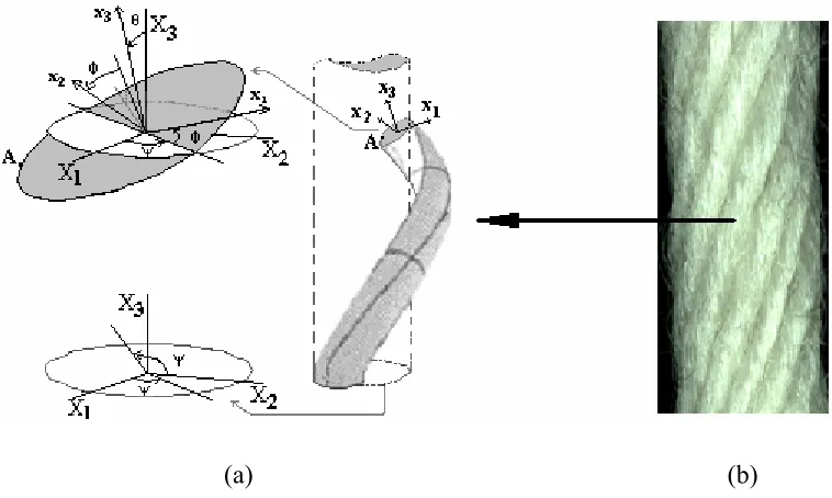
Consider a yarn made from n strands of radius r and length L whose centerlines are wound on a cylinder of radius R in a right handed helix (Fig.1a,b). Each strand is considered as an elastic inextensible unshearable circular single yarn. The configuration of a strand (i) is specified by the position of a curve in space ri(s), where s is the arc length along the central axis of the yarn. Let {X1, X2, X3} be a fixed rectangular Cartesian coordinate system and {x1, x2, x3}, a moving coordinate system (Fig.1(a)) whose first two axes coincide with the principal axes of the strand cross section, while the third axis coincides with the tangent to the strand axis, i.e.
i 3
d ds = r
(a) (b)
Figure 1 (a) Schematic diagram of a strand wound on a cylinder, showing fixed Cartesian and moving coordinate frames; (b) the image of a multi-ply yarn obtained at CSIRO.
Let ψ, θ, φ (three Eulerian angles) be the angular rotation of the single yarn around the X3 axis, the helical ply angle of the strand and the twist angle of a strand, respectively. The centreline of strand (i) can be expressed in the fixed frame as follows (Neukirch and van der Heijden, 2002) i
( )
s in( )
s−
=
r K r1
1 , (2a)
with n
cos sin n n sin cos n n π π − π π = K 2 2 0 2 2 0
0 0 1
and r1T
( ) (
s = R sin , R cos , s cosψ − ψ θ)
, (2b,c)where d sin ;
( )
ds R
ψ = θ ψ =
0 0 (3a,b)
[image:4.612.123.502.85.312.2]The moving and fixed coordinates are related by an orthogonal transformation that can be written as follows
sin sin cos cos cos cos sin sin cos cos cos sin
sin cos cos sin cos cos cos sin sin cos sin sin
cos sin sin sin cos
− ψ φ + ψ φ θ ψ φ + ψ φ θ − φ θ
= − ψ φ − ψ φ θ ψ φ − ψ φ θ φ θ
ψ θ ψ θ θ
1 1 2 2 3 3 x X x X x X (4)
We then have
(
)
3
T = sin cos ,sin sin ,cosθ ψ θ ψ θ
x . (5)
Since the centreline of each strand lies on a cylinder of radius R, a cylindrical coordinate frame
{
e e eR, ,ψ X3}
is introduced as follows3
R 1
2
X 3
sin cos 0
cos sin 0
0 0 1
ψ
ψ − ψ = ψ + ψ
e X e X e X . (6)
Let k be the curvature vector whose components (k1, k2, k3) relative to the moving frame are the curvatures in the principal directions x1 and x2 and the local twist of the strand, respectively. The governing equations of the evolution of the frame {x1,x2,x3} along a strand centerline are expressed as follows (Love, 1944),
i
i
d
ds = ×
x
k x , (7)
where, from (4),
1
d d
k sin sin cos
ds ds
θ ψ
= φ − θ φ, (8a)
2
d d
k cos sin sin
ds ds
θ ψ
3
d d
k cos
ds ds
φ ψ
= + θ. (8c)
By noting that the distance between the centerlines of two adjacent strands ri(s) and ri+1(s) is 2r and the tangents at a contact point of two adjacent strands are orthogonal to the line connecting the centreline points at the contact point, the following geometrical conditions can be obtained (Neukirch and van der Heijden, 2002)
m cos cos m sin ,
n m cos sin sin m sin ,
n π
+ θ − θ − ρ=
π
θ + θ θ − =
2 2 2 2 2 4 2 2 2 0 (9a,b)
where m si 1 si, R
R r
+ −
= ρ = .
Here si+1 and si are the arclength parameters of the two sections in contact. 2.2 Geometrical constraints imposed by topological conservation conditions
Topological studies on the behaviour of closed rods undergoing arbitrary deformations have defined the concepts of link, twist and writhe (Fuller, 1971), where the link can be thought of as the number of turns put into a bent rod before gluing the ends together to form the closed rod. According to the topological conservation law developed by Fuller (1971, 1978), during the deformation of the closed rod the link, Lk, is invariant and is expressed as follows
L = T + W , (10) k w r
(
)(
)
w 3
' '
i j i j
r 3 i j
i j
1
T = k ds,
2π
r (s )×r (s ) r(s )-r(s ) 1
W = ds ds ,
4π r(s )-r(s )
ζ
ζ ζ
∫
∫∫
(11a,b)where the integrations are performed over the entire length of the rod and the primes denote differentiation with respect to the argument. The above assumes a closed rod but extensions of the topological conservation law apply to open rod configurations. Neukirch and van der Heijden, (2002), developed the theory for a multi-ply structure consisting of multiple rods(strands) and we shall apply these results to multi-ply yarns.
In the yarn spinning process the spinning twist, or total end rotation, of a single yarn can be considered as link. This link is fixed when the ends of the yarn are tied together after forming a hank from a number of loops consisting of n strands of length L, i.e., the loop number and length is n/2 and 2L, respectively. Since the yarn’s cross-section is assumed circular, the twist is regularly distributed along the yarn (i.e., k3 is constant), and hence (11a) gives (noting that the total length of yarn is nL, where n in the present case is even)
w 3
nLk T =
2π . (12)
Furthermore, it was shown by Neukirch and van der Heijden, (2002) that for a multi-ply structure of constant angle θ the writhe is given by
r
(
)
L
W sin n cos .
2 R
= θ σ − θ
π (13)
and on combining (10), (12), (13) and (14) we find the following relation
3
sin 2 k =
2R
θ
τ + . (15)
We shall also be interested in the number of helical turns formed in the yarn for a given link parameter τ, as measured by the so-called ply twist. To derive a formula for this ply twist note that the number of turns of a helical thread of length L, helix radius R and angle θ is given by Lsin(θ)cos(θ)/(2πR). We thus define
sin cos Wr
Ply twist
2 R nL
θ θ
= = −
π , (16)
where Equation (13) has been used and n is even. While writhe is a mathematical concept, we see that in the practical case of a plied yarn structure, writhe is essentially equivalent to the ply twist. The minus sign merely reflects the fact that a positive τ produces a left-handed helix with negative θ. From Equation (14), we also define
Spinning twist = 2τπ = nLLk . (17)
Both twist measures have units of turns per metre and will be used in Section 4 in the comparison against experimental results.
2.3. Kinetic Governing Equations
In this section we derive an expression for the inter-strand pressure of a multi-ply subject to the constant-link constraint discussed in the previous section. The force and moment balance equations for a single strand in the multi ply structure are (Fraser and Stump (1998), Thompson et al. (2002), Neukirch and van der Heijden (2002))
d
, ds + =
F
d d
+ = , ds ds×
M r
F 0 (18b)
where F and M are the internal force and moment, respectively, and p is the pressure (contact force per unit length) on the strand exerted by the neighbouring strands. We shall assume linear constitutive relations between the generalized stresses (the moments M) and the generalised strains (the curvatures and twist k1, k2, k3) so that we can write
3
3 3 3
d
B Ck ,
ds
= × x +
M x x (19)
where B and C are the bending and torsional stiffness of the strand, respectively. Taking into account the geometry of the strands in the multi-ply (see Figure 2) we can write for the pressure
j 1, j+ j 1, j− ,
= +
p p p (20)
where (j-1) and (j +1) label adjacent strands of the strand under consideration (j). pj+1,j and pj-1,j are the pressures exerted on strand (j) by strands (j+1) and (j-1), respectively. We shall call them inter-strand pressures and if we denote their magnitudes by pj+1,j and pj-1,j then we can write
( )
( )
( )
( )
( )
( )
( )
( )
( )
( )
( )
( )
j j 1 j 1 j j 1 j 1
j 1, j j 1, j j 1, j j 1, j
j j 1 j 1 j j 1 j 1
s s s s
s p s ; s p s .
s s s s
+ + − − + + − − + + − − − − = = − −
r r r r
p p
r r r r (21a,b)
Here we have assumed frictionless contact so that the pressures act normal to the contacting surface. By symmetry of the uniform multi-ply yarn we have |pj-1,j| = |pj+1,j| = pj and hence the total pressure on strand (j) is given by
j j 1, j j 1, j j R R
2
p 1 cos msin e pe , n
+ −
π
= + = ρ − θ − =
p p p (22)
Figure 2 The inter-strand pressures on strand (j) from strand (j+1) and strand (j+1) of a multi-ply yarn. The cross-section of the yarn is only schematic.
Since we have assumed a helical shape for the strand the moment M can be computed from Equations (2) and (19). It was shown in Neukirch and van der Heijden, (2002) that the balance equations (18) can then be solved explicitly. In addition to the components of the force F, one finds the multi-ply equilibrium equation for the angle θ,
2 2
3 o o
3
r F rM
2n sin cos k r n cos 2 sin cos 0
B B
ρ ρ
θ θ + ρ γ θ + θ − θ = (23)
and an expression for the pressure, which, after eliminating k3, reads
(
)
2
2 2 2
0 0
3 3
sin
p nBsin r F cos rM sin
n r cos 2 θ
= θ + ρ θ − ρ θ
ρ θ (24)
Here we have allowed for an end force F0 and an end moment M0, both applied axially to the overall yarn (they enter as boundary conditions to Equation (18)). γ = CB is the ratio of the strand torsional to bending stiffness. In Equation (23) the strand local twist k3 is a constant that is still to be determined.
2.4. Combining the Kinetic Governing Equations with the Topological Constraint
rotation within it. In this case what one controls is the link or spinning twist as discussed in Section 2.1. Thus, treatingτas a given parameter, a combination of (15) and (23) yields
2 2
3 r F0 rM0
2n sin cos n sin 4 r n cos 2 sin cos 0
4 B B
ρ ρ
γ
θ θ + θ + τρ γ θ + θ − θ = . (25)
3 Self-balance of a multi-ply yarn
When no loads are applied (Fo = Mo = 0), the multi-ply yarn is said to be in its self-balanced state. The equilibrium equation (25) and the expression for the pressure (24) then reduce to
3
4
3 3
2sin cos sin 4 r cos 2 0,
4 Bsin
p .
r cos 2
γ
θ θ + θ + τρ γ θ =
θ =
ρ θ
(26a,b)
In these expressions ρ is to be considered a function of n, r and θ through Equation (9). For given initial yarn parameters (count, number of strands and bending and torsional stiffnesses) and the link parameter τ, Equation (26a) can be solved in conjunction with Equation (9a,b) to give the ply angle θ and the ratio ρ, upon which the Equation (26b) can be used to obtain the pressure in the zero-torque state.
4. Numerical examples and discussion
In this section the balance of multi-ply yarns consisting of different numbers of strands will be analyzed and compared with experimental data. The inter-strand pressure and the total pressure on strands for the case of balanced multi-ply yarns are also calculated. The analysis is carried out with a range of yarn counts and spinning twists.
4.1. Experimental method used to measure the ply in zero-torque multi-ply yarns
wool causes several time-dependent effects. For this reason the balance in multi-ply yarns has been measured wet to ensure that the wool polymer is at conditions above the glass transition and the storage history of the material is eliminated.
To measure the ply at the zero torque balance point a single wool yarn was wound onto a one metre drum to form a series of yarn loops, either 1, 2 or 3 loops. The two ends of the yarn were tied together thus forming a topologically closed system. On removal from the drum one paper clip was attached to the loops of yarn and the loops were allowed to rotate to form a plied structure due to the inherent torque in the single yarns. The initial 1, 2 or 3 loops formed either a 2-ply, 4-ply or 6-ply arrangement respectively, nominally 0.5 m long. The plied yarn was immersed in a column of water at ~20°C and allowed to relax for 15 mins before the ply twist was measured wet. The method was repeated 10 times and the results averaged. Yarns of 19.1, 40 and 80 Tex with a range of twist factors, usually 60 to140, were measured.
4.2. Analysis of the balanced yarn structure
In this section multi-ply yarns comprising 2, 4, 6 strands will be analyzed by determining the relationships between the spinning twist (link) and the ply twist (writhe) or the helical ply angle. For isotropic materials, the ratio of torsional to bending stiffness (γ) of a circular rod is related to Poisson’s ratio (ν) by the equation, γ = 1 /(1+ ν) (Thompson et al., 2002). The mechanical properties of wool fibres are highly anistropic, and for fibres, γf is around 2/3 (dry) and 0.1 (wet) (Postle et al., p.20, 1988). The value of γy for spun yarns is more complex and is influenced by the yarn structure as well as the material properties of the fibres.
of 0.7 is used and, where appropriate, a range of γy from 0.5 to 1.0. Furthermore, in this analysis, the radius of the strand is calculated as a function of the yarn count, packing fraction and fibre density. For example, the packing fraction used for wool worsted yarns is 0.63, the fibre density is 1.31 g/cm3 and the single yarn radius is determined using Grosberg’s formulae (Booth, 1975). Plied yarns consisting of two strands (n = 2, so that R = r, or ρ=1) form an important practical case of multi-ply yarns. The effect of spinning twist initially applied to a single yarn or strand on the conditions for the balance of a 2-ply yarn is described in Figures 3, 4 and 5.
Figure 3 shows the relationship between the spinning twist and the ply angles for a range of strand counts and various ratios of torsional stiffness to bending stiffness. Figures 4 and 5 express the ply twist and the ratio of ply twist to spinning twist respectively against the spinning twist.
[image:14.612.185.440.83.307.2]Comparison of Figures 3 and 4 shows that for a given yarn count (linear density), the (negative) ply helical angle and the ply twist both increase with spinning twist. Figure 3 shows that for a given spinning twist, the ply helical angle increases with the strand count but the ply twist decreases as shown in Figure 4, simply due to the geometry, i.e., the increased radius of the higher count yarn. Although the effect of the strand count on the ply twist is high, the effect of the ratio of torsional stiffness to bending stiffness of strands γ on the ply twist at the point of balance is low. Similar behaviour is seen in Figure 5 where the familiar textile ratio of ply twist to spinning twist decreases with increasing strand count and spinning twist but is not strongly dependent on γ.
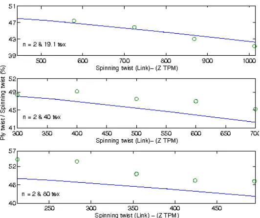
The predictions for the zero-torque balance point are compared with preliminary experimental results for a series of two-ply yarns using single yarns of 19.1 Tex, 40 Tex, 80 Tex and γ = 0.7 in Figure 6. The results obtained from the present work are in good agreement with the experimental ones for a large range of yarn counts and their differences are approximately 10% for two-ply yarns.
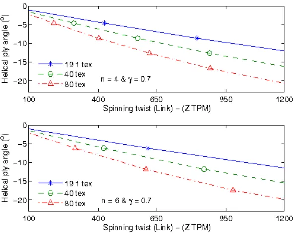
The helical ply angle and the ratio of ply twist to spinning twist are plotted against spinning twist in Figures 7 and 8 for 4-ply and 6-ply yarn using strand counts of 19.1, 40 and 80 Tex. Interestingly, the ply angle for a particular strand count shows a relatively small change as the number of plies increases whereas the ratio of ply twist to spinning twist decreases significantly as the number of plies increases. For example, at a spinning twist of 950, the ply angle is approximately 22° for the 80 Tex 2-ply yarn (Figure 3) and about 18° and 17° for the 4-ply and 6-ply 80 Tex yarns (Figure 7), whereas the ply twist to spinning twist ratio is about 33%, 19% and 9.5% respectively(Figures 5 and 8). Again this large change in the ratio is due to the increased yarn radius as the ply number increases.
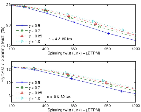
Although the effect of the stiffness ratio γ on the balance is not large, see both Figures 5 and 9, the results show that when the γ ratio increases the ratio of ply twist to link increases, reflecting a small increase in the helical ply angle.
Figure 9 The ratio of ply twist to spinning twist plotted against the spinning twist for balanced 4-ply and 6-ply yarns with different γ ratios using single yarns of 80 Tex.
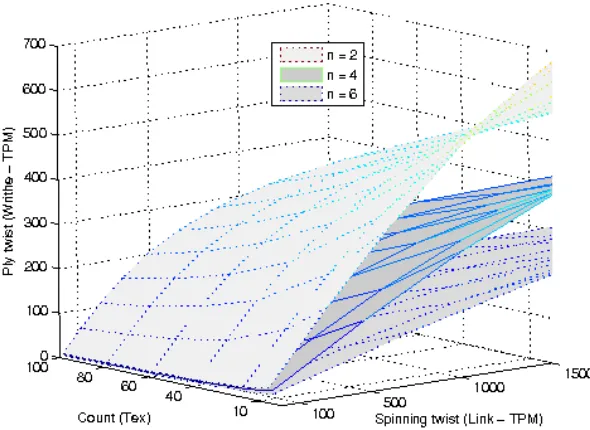
Figure 10 combines a number of features to show the balanced ply condition against strand count, spinning twist and number of strands in the multi-ply structures.
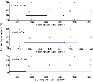
[image:19.612.164.459.188.403.2]The predictions for the balance point based on topological conservation are also compared with several preliminary experimental results for multi-ply yarns (n = 4 and n = 6). The theory shows that the ratio of ply twist to spinning twist decreases rapidly as the number of plies increases. The experimental data show a similar trend and the ratio decreases significantly as the number of plies increases, see Figure 11. While the agreement between theory and experiment is good for the 2-ply case in Figure 6, the error between theory and experiment increases as the number of plies increases, see Figure 11. This may relate to the simple geometric model used in Section 2.1
that locates the position of the strands on a cylinder. This approximation is true for 2-ply yarns but becomes less accurate as the number of plies increases.
4.3. Pressure on strands of a multi-ply yarn
[image:20.612.150.473.163.446.2]In this section, three single yarns of 40, 20 and 13.3 Tex were modelled to investigate the inter-strand and total pressures at the balanced point of multi-ply yarns comprising 2, 4 and 6 inter-strands. The bending stiffness B (mN.mm2) of a strand is determined as follows (Ly and Denby, 1984, Postle et al., 1988)
f
2
12 2
1 2
Ed T
B 62.5 10= × − C C ×0.97
ς (27)
where C1, C2 are the correction factors from the influence of the fibre diameter distribution and the yarn twist respectively; E (mN/mm2) is Young’s modulus of wool material; df (µm) is the fibre diameter; ς(g/cm3) is the fibre density and T (Tex) is the yarn count of strands. In the present work, these quantities are chosen as follows: C1 = 1.28 (Postle et al., 1988) associated with df = 19 µm; E = 4 x 10⁶ mN.mm-2 (Ly and Denby, 1984); ς = 1.31 g.cm-3 (Owen, 1964) and C2 is given by (Postle et al., 1988)
(28)
where γf is the ratio of the fibre torsional stiffness to its bending stiffness and γf = 0.5 in the standard laboratory conditions (Ly, 1983 and Postle et al., 1988)) and ψ is the strand twist angle defined in Section 2.1.
Figure 13 The calculated inter-strand and total pressure for 2, 4 and 6-ply yarns at the balance point using 20 Tex strands.
Figure 12 The calculated inter-strand and total pressure for 2, 4 and 6-ply yarns at the
These results identify some interesting behaviour for the multi-ply yarns. While the differences in the total pressure are negligible at low spinning twist (for example, less than 300tpm for 40 Tex, 400tpm for 20 Tex and 500tpm for 13.3 Tex), a clear difference is observed for the inter-strand pressure. Generally, the effect of the number of inter-strands on these two kinds of pressure shows two contrasting effects. As the number of strands increases, the total pressure decreases but the inter-strand pressure increases. Furthermore, the total pressure tends to reach a stable value with increasing spinning twist. This stable total pressure is particularly evident for the 6-ply yarns from 40 Tex yarns. The effect of inter-strand pressures may have very practical consequences in relation to fabric performance. The inter-strand pressures may influence the lateral compression of strands and influence the bulk in the strand and multi-ply yarn as well as the movement of fibres in the yarn structure. The latter effect has potential to affect the shedding
Figure 14 The calculated inter-strand and total pressure for 2, 4 and 6-ply yarns at the
of fibres and the formation of pills in textile products and further studies will address this behaviour.
[image:24.612.159.462.293.533.2]In order to further evaluate the influence of structural properties of a multi-ply yarn on the inter-strand and total pressures, three multi-ply yarns of the same resultant count (80 Tex) prepared from 2x40tex, 4x20tex and 6x13.3tex were considered. Figure 15 depicts the total pressures and inter-strand pressure with respect to spinning twist for the three multi-ply yarns. The results in Figure 15 confirm the influences of the number of strands on the total pressure and inter-strand pressure on strands.
5. Conclusion
The equilibrium configuration of a balanced multi-ply yarn has been analysed and predicted using the yarn kinetic governing equations and geometrical constraints based on the principle of
Figure 15 The calculated inter-strand and total pressure for 80 Tex yarns at the
topological conservation. The effects of the initial single yarn parameters (spinning twist, diameter (count), yarn torsional and bending stiffness) on the balance point in 2-ply, 4-ply and 6-ply yarns has been established. The model results show good agreement at low numbers of strands with preliminary experimental results on wool worsted multi-ply yarns obtained at CSIRO. The theoretical analysis shows how the structural parameters of multi-ply yarns, such as spinning twist, initial single yarn count, number of strands and the fibre material properties affects the geometry of a multi-ply yarn. The interstrand pressure in multi-ply yarns has been calculated and provides a basis for studying related yarn and fabric structural properties, e.g., yarn bulk, fibre migration and pilling.
Acknowledgements
This work was supported by a grant of computing time from Australia Partnership for Advanced Computing (APAC) National Facility. Canh-Dung Tran is supported by a CSIRO Postdoctoral Research Fellowship. The authors also note the technical assistance of Julia Marsh which was supported through an EPSRC collaborative grant. All of this support is gratefully acknowledged.
References
Batra, S.K., 1973. The normal force between twisted filaments, Part 1: The fibre wound on cylinder model analytical treatment, J. Text. Inst. 64, 209-219.
Bennett, J.M. and Postle, R., 1979. A study of torsional stability in plied yarns, J. Text. Inst. 70, 142-151.
Booth, J.E., 1975, Textile Mathematics, Vol 2, Textile Institute, Manchester.
Coleman, B.D. and Swigon, D., 2000. Theory of super-coiled elastic rings with self contact and its application to DNA plasmids, J. of Elasticity 60, 173-221
Fuller, F.B., 1971. The writhing number of a space curve. Proc. Nat. Acad. Sci. USA 68, 815-819.
Fuller, F.B., 1978. Decomposition of the linking of a closed ribbon: a problem from molecular biology. Proc. Nat Acad. Sci. USA 75, 3557-3561.
Gracie, P.S., 1960. Twist geometry and twist limits in yarns and cords, J. Text. Inst. 56(7), 271-288.
Hearle, J.W.S., 1959. The mechanics of twisted yarns: The influence of transverse forces on the tensile behavior, J. Text. Inst. 63(9), T389-T340.
Hearle, J.W.S. and Yegin, A.E., 1972a. The snarling of highly twisted monofilaments Part I: The load elongation behavior with normal snarling, J. Text. Inst. 63(9), T.477-T489.
Hearle, J.W.S. and Yegin, A.E., 1972b. The snarling of highly twisted monofilaments Part II: Cylindrical snarling, J. Text. Inst. 63(9), T.490-T501.
Love, A.E.H., 1944. A treatise on the mathematical theory of elasticity, Cambridge, p 414.
Ly, N.G., 1983. The contribution of fibre diameter distribution to the bending rigidity of yarns, J. Text. Inst., 74, 228-230.
Ly, N,G. and Denby, E.F., 1984. Bending Rigidity and Hysteresis of Wool Worsted Yarn, J. Text. Inst., 54, 180-187.
Maddocks, J.H., 1987. Stability and folds. Archive for Rational Mechanics and Analysis 99(4), 301-328.
Neukirch, S. and van der Heijden, G.H.M., 2002. Geometry and mechanics of uniform n-plies: from engineering ropes to biological filaments, J. Elasticity 69, 41-72.
Owen, J.D., 1965. The application of Searle’s single and double pendulum methods to single fibre rigidity measurement, J. Text. Inst. 56, T329-T339.
Platt, M.M., Klein, W.G. and Hamburger, W.J., 1958a. Mechanics of elastic performance of textile materials, Part XIII: Torque development in yarn systems: single yarn, Textile Res. J. 28(1), 1-14.
Platt, M.M., Klein, W.G. and Hamburger, W.J., 1958b. Mechanics of elastic performance of textile materials, Part XIV: Some aspect of bending rigidity of singles yarns, Textile Research J., 29, 611-627.
Postle, R., Carnaby, G.A. and De Jong, S., 1988. The Mechanics of Wool Structures, New-York: John Wiley & Son.
Postle, R., Burton, P. and Chaikin, M., 1964. The Torque in Twisted Singles Yarns, J. Text. Inst. 55, T448 – T461.
Thompson, J.M.T, van der Heijden, G.H.M and Neukirch, S., 2002. Super-coiling of DNA plasmid: mechanics of the generalized ply. Proceedings of the Royal Society of London A 458, 959-85.
Tran, C.D. and Phillips, D.G., 2006b. Predicting torque of worsted singles yarn using an efficient RBFN based method. J. Text. Inst. (accepted for publication).
Treloar, L.R.G., 1956. Geometry of multi-ply yarns, J. Text. Inst. 47, T348-T368.
Van der Heijden, G.H.M., Neukirch, S., Goss, V.G.A. and Thompson, J.M.T., 2003. Instability and self-contact phenomena in the writhing of clamped rods, Int. J. Mech. Sci. 45, 161-196.
Van der Heijden, G.H.M., Champneys, A.R. and Thompson, J.M.T., 2002. The spatial complex localization in twisted elastic rods constrained to a cylinder, Int. J. Solid. Struct. 39, 1863-1883.