University of Southern Queensland
Faculty of Engineering and Surveying
A MATLAB-based Framework for
Engineering Design Evaluation
via Virtual Prototyping
A dissertation submitted by
George Bernardel
in fulfilment of the requirements of
ENG4111 and 4112 Research Project
towards the degree of
Bachelor of Engineering (Computer Systems)
Abstract
Virtual prototyping is gaining increased relevance as a viable cost-effective alternative to the
more traditional methods of physical prototyping for engineering design. Today
=
s computer
systems are well-able to handle the complex system equation solutions and
visualisation/animation overheads in pseudo real-time. This project develops a framework,
using MATLAB/Simulink
®
, whereby engineering component definitions are assembled into
systems and simulated for dynamic performance.
Engineering components are largely defined by spatial extent, behavioural characteristics within
a wide spectrum of operating conditions, material properties and production-related attributes.
These feature definitions, and other data, can be captured within digital files and supplied by
manufacturers as the means to encapsulating the essential
>
nature
=
of their product. An initial
protocol is established to capture these features in dedicated
A
virtual definition files
@
directories.
MATLAB is a powerful computational engine for the solution to, and visualisation of, largely,
matrix-based problems. Simulink, integrated with MATLAB, is a sophisticated tool for the
simulation of system dynamic behaviour. These two products, in their student edition forms, are
shown to integrate seamlessly, via a series of graphical user interface controls, as a relatively
easy-to-use virtual prototyping tool.
The main outcome of the project is a MATLAB/Simulink application
A
VirtProtoBench
@
, which
uses the virtual prototyping methodology to:
•
load and assemble virtual component file definitions;
•
assemble components into a required engineering system;
•
use relevant system equations and component behaviour parameters
to simulate the working system; and
•
provide simultaneous system animation and parameter feedback.
University of Southern Queensland
Faculty of Engineering and Surveying
ENG4111 & ENG4112
Research Project
Limitations of Use
The Council of the University of Southern Queensland, its Faculty of Engineering and
Surveying, and the staff of the University of Southern Queensland, do not accept any
responsibility for the truth, accuracy or completeness of material contained within or
associated with this dissertation.
Persons using all or any part of this material do so at their own risk, and not at the risk
of the Council of the University of Southern Queensland, its Faculty of Engineering and
Surveying or the staff of the University of Southern Queensland.
This dissertation reports an educational exercise and has no purpose or validity beyond
this exercise. The sole purpose of the course pair entitled "Research Project" is to
contribute to the overall education within the student’s chosen degree program. This
document, the associated hardware, software, drawings, and other material set out in the
associated appendices should not be used for any other purpose: if they are so used, it is
entirely at the risk of the user.
Prof G Baker
Dean
Certification
I certify that the ideas, designs and experimental work, results, analyses and
conclusions set out in this dissertation are entirely my own effort, except where
otherwise indicated and acknowledged.
I certify that the work is original and has not been previously submitted for assessment
in any other course or institution, except where specifically stated.
George Bernardel
Student Number: 0039740960
________________________________
Signature
Acknowledgments
The author would like to thank Ass. Prof. Sai-Cheong Fok for his guidance and
feedback during the course of this project work. The author also thanks his employer,
Geoscience Australia, for support, both monetary and time-off, during the course of this
project work and all previous subjects undertaken at the University of Southern
Queensland towards the fulfillment of the Bachelor of Engineering degree program.
George Bernardel
Contents
Abstract
i
Acknowledgements
iv
List
of
Figures
viii
Glossary of Terms
xi
Chapter 1 Introduction
1
1.1 Project Aim and Objectives ………...… 2
Chapter 2 Engineering Prototyping Methodology
4
2.1 Prototyping: Engineering Design Evaluation ... 4
2.2 Prototyping Technology Evolution ... 5
2.3 Virtual Prototyping Defined ... 6
2.4 Future Trends in Virtual Prototyping ... 8
Chapter 3 Virtual Prototyping in the Marketplace
10
3.1 A Review of Virtual Prototyping Applications ... 10
Chapter 4 MATLAB/Simulink: Evaluation for Virtual
Prototyping
15
4.1 Design Basis for a Virtual Prototyping Tool ... 15
4.2 Hardware/Software Issues for a Virtual Prototyping Tool ... 16
4.3 MATLAB for Engineering Systems Design ... 17
4.4 SIMULINK for Engineering Systems Simulation ... 21
Chapter 5 VirtProtoBench: A MATLAB/Simulink Application for
Feature-Based Virtual Prototyping
24
5.1 An Overview of VirtProtoBench ... 24
5.2 VirtProtoBench Development: Hardware/Software Environment ... 26
5.3 VirtProtoBench Evaluation: Geared-Hoist Mechanism ... 28
5.3.1 Kinematics of Load-Lifting Force ... 30
5.3.2 Dynamics of Gear Tooth-Bending Stress ... 32
Chapter 6 VirtProtoBench: GUI Design Methodology
34
6.1 GUI Design Philosophy: User Perspective ... 34
6.2 GUI Tools for Handling User Input ... 36
6.3 GUI Tools for Handling Application Output ... 38
Chapter 7 VirtProtoBench: Component Features Management 41
7.1 Component Definitions: Feature Encapsulation and Standardization ... 41
7.2 Virtual Definition Files Directory: Attempt at Feature-Based Component
Definitions ... 44
7.3 Component Importation and Assembly ... 46
7.4 Evaluation: Geared-Hoist Mechanism ... 49
Chapter 8 VirtProtobench: Assembled System Management
52
8.1 System Definition: Rules and Verification ... 52
8.2 System Assembly Management ... 54
8.3 Evaluation: Geared-Hoist Mechanism ... 57
Chapter 9 VirtProtoBench: Simulated System Management
61
9.2 Simulation Management ... 64
9.3 Evaluation: Geared-Hoist Mechanism ... 68
Chapter 10 Conclusions and Further Work
73
10.1 Achievement of Project Objectives ... 73
10.2 Further Work ... 74
10.2.1 Bugs and Limitations ... 75
10.2.2 Augmented Reality ... 76
10.2.3 Object-Oriented Design ... 77
10.2.4 Multi-Domain Engineering Design ... 78
References
80
Bibliography
84
Appendix A Project Specification
85
Appendix B Application Snapshots
87
List of Figures
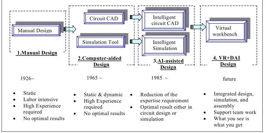
2.1 Chronology of prototyping methodologies (from Xiang et al., 2001). …... 5
3.1 Modelica graphic of a simple servo system model (taken from Otter &
Elmqvist, 2000). ... 13
3.2 Modelica text-based model of the system in Fig. 3.1 (taken from Otter &
Elmqvist, 2000). ... 13
3.3 Modelica graphic of the motor component in the system of Fig. 3.1 (taken
from Otter & Elmqvist, 2000). ... 13
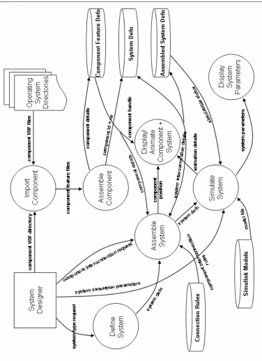
4.1 Context-level diagram for a typical VP application. ... 16
4.2 Idealised representation of Simulink model use for VP simulation. ... 22
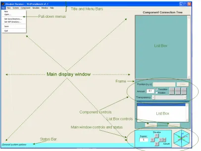
5.1 Main application window for VirtProtoBench. ... 25
5.2 Data flow diagram-like represeantation of VirtProtoBench application. 27
5.3 Idealized representation of a geared-hoist mechanism for load lifting
(taken from MathPros Homepage). ... 29
6.1 VirtProtoBench main application figure window (cf Figure 5.1). GUI
control labels and arrows highlighted in olive green. ... 35
6.2 Pull-down menu
Component->Load…
dialogue window
.
... 37
6.3 Pull-down menu
System->System Parameters
dialogue window giving
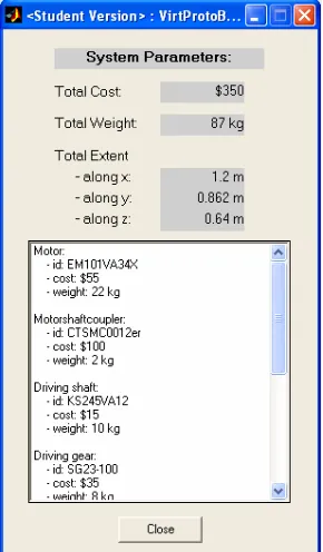
feedback on status of assembled gear-hoist system. ... 38
7.1 A database representation of a mechanical counter-bore compound feature
comprising hole feature primitives with reference to a [x1,y1,z1] reference
frame (taken from Case et al., 2004). ... 42
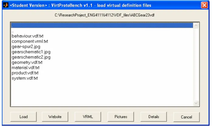
7.2 Screen snapshot of some component VDF directories in Windows Explorer
needed to build a geared-hoist mechanism. ... 50
7.3 Screen snapshot of VirtProtoBench with graphical representation of all
components defined by their VDF directories as shown in Figure 7.2. .... 51
8.1 Expanded view of VirtProtoBench right-hand-side UIC list boxes for the
component arrangement depicted in Figure B5. ... 58
8.2 System connection tree as in Figure 8.1, but with the motor connected to
one of the motorshaftcoupler devices. ... 59
9.1 VirtProtoBench Simulink model file
test3.mdl
used to manage the simulation
of the simple two gear hoist mechanism used to evaluate the tool. Labels and
arrows highlighted in red identify standard functional blocks and do not form
part of the model file. ... 62
9.2 Simulation dialogue window invoked by activating
Simulate->Simulation
Parameters…
in the top-level menu of VirtProtoBench. ... 65
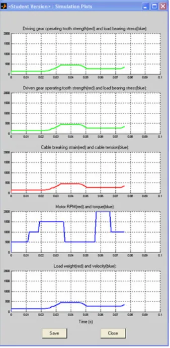
9.3. Window created by
test3gui.m
for the real-time plotting of parameters
during the simulation run associated with Simulink model
test3.mdl
. ... 66
9.4. VirtProtoBench Simulink model file
test3.mdl
highlighted for encoded
system equation terms and system state verification. Green and red annotations
do not form part of the model. ... 70
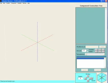
B.1. VirtProtoBench start-up panel. ... 88
B.2. VirtProtoBench main application figure window with pull-down menu
choice for toggle floor plan grid highlighted:
View->Display_Grid->Display_Zlines
. ... 89
B.4. Motor component schematic displayed via
Pictures
push button on load
component dialogue window (see Figure B3). ... 90
B.5. VirtProtoBench main display window showing arranged components
before attempted assembly into a geared-hoist mechanism. ... 90
B.6. Geared-hoist system assembly as driving gear id 8 is about to be connected
to driven gear id 9. The gear connection angle is established by the slider bar
on the connection dialogue window. ... 91
B.7. System status dialogue, invoked by
System->System Parameters
, providing
feedback on the current status of assembled gear-hoist system. ... 91
B.8. Simulatable gear-hoist mechanism with top perspective view provided by a
secondary MATLAB figure window activated by pull-down menu option
Window->Duplicate View
. ... 92
B.9. Geared-hoist mechanism with simulation parameters dialogue window
ready for simulation. ... 92
B.10. Geared-hoist mechanism during simulation with main display window
animation overlayed by interactive simulation dialogue (window to right)
and real-time feedback plots of simulation parameters (window to left). Note
plotting axes titles do not reflect parameters being plotted. ... 93
Glossary of Terms
AGMA
:American Gear Manufacturers Association. An association of American gear
designers and manufacturers, which establishes many of the design criteria for gears and
gear systems in the United States.
AI
: Artificial Intelligence. The branch of computer science that deals with developing
computer programs that can solve problems creatively.
Augmented Reality
: A growing branch of Virtual Reality which allows for such things
as the overlay of virtual objects on top of real-world objects.
CAD
: Computer Aided Design. Computer programs used in engineering and
manufacturing to aid in engineering systems drawing.
CAE
: Computer Aided Engineering. The use of computers to aid in all the conceptual
and analytical phases of engineering design work.
Component
. An artifact that is one of the individual parts of which a composite entity
is made, and, in particular, that can be detached from or attached to a system.
DAI
: Distributed Artificial Intelligence. A subfield of AI research dedicated to the
design of solutions for complex problems.
GUI
: Graphical User Interface. A computer screen bit-mapped display allowing the user
to interact with the application or host operating system via intuitive graphical objects.
Kinematics
: the study of objects in motion.
Moment-of-Inertia
. A measure of a solid body’s ability to resist changes to rotational
speed about a specific axis.
Multi-domain Engineering Design
: The design of an engineering system where more
than one form of physical interaction is considered.
Object-oriented Design
: Simply, a programming style in which the encapsulation of
data, and the functions acting on that data, play a central role.
Prototyping
: Generally, the creation of a model and the simulation of all aspects of a
product.
RPM
: Revolutions Per Minute. A general term for the angular speed of a body rotating
around a consistent axis.
Simulation
: A technique of representing a real-world system by a computer program,
which imitates the internal processes characterising the system.
System
: A group of independent but interrelated elements comprising a unified whole.
Topology
:A mathematical procedure used to establish spatial relationships, such as
coincidence and connectivity.
Torque
: Also called the moment of force. The tendency of a force to rotate the body to
which it is applied.
VP
: Virtual Prototyping. Simply, a real-time computer-aided design and simulation
process to verify the functional specifications of an engineering system.
VR
: Virtual Reality. A hypothetical three-dimensional visual world of objects generated
by a computer.
Chapter 1
Introduction
This document represents the final requirement for the project work undertaken in the
combined semester 1 and 2 units
ENG4111
and
ENG4112 Research Project
for the final
year of the Bachelor of Engineering degree program
1at the University of Southern
Queensland. It follows the submissions of the
Project Proposal
(see title page), the
Project Specification
(see Appendix A) and an oral presentation in a conference setting.
It is the formal outcome of the methodology employed in researching, planning and
executing the project topic.
The research topic undertaken by the author involves, largely, an investigation into the
use of MATLAB
®
and Simulink® as a software tool for virtual prototyping
development. Virtual prototyping involves the assembly and simulated interaction of a
number of engineering components whose physical features, such as geometric and
behavioural attributes, are encapsulated in digital form. The visualisation of the ‘virtual’
assembled system and investigation of the simulated physical interactions are provided
in as realistically possible form to mirror those in the ‘real’ world, and thereby provide
some feedback on the integrated systems design without recourse to cumbersome,
time-consuming and expensive physical construction and testing.
1
The author is enrolled in the Computer Systems stream.
The project goes beyond the integration of MATLAB static scripts and Simulink
dynamic models. The scripts and models will need to be managed by a
human-controllable interface requiring the use of MATLAB’s GUI toolset. When loading data
for a virtual component definition a common format will need to be prescribed. The
developed MATLAB/Simulink tool will need to adapt to the engineering environment
modelled, such as, for example, mechanical, electrical or fluid dynamics. These, and
other issues, require a framework in which the developed software tool is to effectively
interact with the virtual engineering component formats, the human system designer and
the nature of the interaction sought.
This document is partitioned into a series of chapters, and sections, each dealing with a
particular aspect of the project work. These largely cover a literature research into VP,
an evaluation of MATLAB/Simulink as a programming environment for a VP tool and
the development of a framework where a prototype application, termed VirtProtoBench,
written in MATLAB/Simulink, is used with feature-based component definitions to
assemble and test a simple mechanical system.
1.1 Project Aim and Objectives
The project aim, taken from the
Project Specification
(see Appendix A), is:
“The project seeks to develop a framework for engineering design
evaluation via virtual prototyping using MATLAB’s computational
engine and GUI tools.
”
As the MATLAB and Simulink environments are widely used in the marketplace for
VP development this project aim is distinguished on the following grounds:
•
Whereas in many VP tools MATLAB is used as the computational tool
hidden behind a proprietary front-end, here it will be used to directly
interact with the user.
MATLAB and Simulink will be used together.
•
Whereas in most VP tools only the physical aspects of component
assembly and interaction are considered, here all product attributes will
be considered in the design process.
The four main project objectives, taken from the
Project Specification
(see Appendix
A), are (where MATLAB refers to the combined MATLAB/Simulink environment):
1.
Critically evaluate MATLAB as a software tool for system design and
performance simulation and visualisation.
2.
Design a framework using MATLAB as a VP tool.
3.
Evaluate the MATLAB-based framework for a simple mechanical
system.
4.
Evaluate the MATLAB-based framework for a simple electrical system.
Chapter 2
Engineering Prototyping Methodology
VP is a direct descendent of engineering prototyping methodologies which have
evolved over many years. The impetus has always been the development of a
functioning product prior to a costly and risky commitment to manufacturing. The
literature is examined to provide an overview of prototyping progression and its current
status in the virtual domain.
2.1 Prototyping: Engineering Design Evaluation
An engineering design is largely a conceptual model of a desired physical system. This
system is an assembly of interconnecting components which are required to interact
such that the system’s behaviour is that expected for its intended inputs and/or
environment.
The method of engineering prototyping rests on the iterative development of a test
version of a final engineering system. With physical prototyping a suite of physical
components are bought and assembled in various ways to examine which permutation
best meets the designer’s objectives, which is usually codified in a “system
requirements” document. Although successful in testing a system prior to its
manufacture and promotion in the marketplace, the need to purchase physical
components means that the system development time may have to rely on the costly
time overheads of component supply, purchase and delivery.
2.2 Prototyping Technology Evolution
In the context of fluid power systems design Xiang et al. (2000) and Xiang et al. (2001)
provide a schematic highlighting the advances in engineering systems prototyping
methodologies from the 1920's to the present (see Figure 2.1).
Manual Design
Circuit CAD Intelligent circuit CAD
Simulation Tool Intelligent Simulation
Virtual workbench
2.Computer-aided Design 1.Manual Design
3.AI-assisted Design
1926~
• Static
• Labor intensive • High Experience
required
• No optimal results
• Static & dynamic • High Experience
required
• No optimal results
• Reduction of the expertise requirement • Optimal result either in
circuit design or simulation
1965 ~ 1985 ~ future
• Integrated design, simulation, and assembly
• Support team work • What you see is
[image:19.595.116.542.405.617.2]what you get 4. VR+DAI Design
Figure 2.1. Chronology of prototyping methodologies (from Xiang et al., 2001).
The 1920s are characterised by manual design techniques, as computers were not
available. Component and sub-system configurations had to be drafted statically on a
edium. This was labour intensive and required a high level of experience from
Optimal design results were generally not achievable as simulation was not possible.
writing m
The system of manual design was in widespread use for many years until the 1960s with
the advent of computers. Design methodologies now became a hybrid of static and
dynamic design. Component and sub-system assembly was still performed manually,
but software could now be devised to implement the physical laws of interaction and so
imulate the assembled system’s behaviour under various initial conditions.
telligent design” became apparent in the 1980s
ith software developments into artificial intelligence (AI). Less was now required of
tion of assembled components in
test environment for system behaviour. This is the VP design paradigm. The “test
puter processor and visualised via computer
raphics primitives driving a screen. The virtual workings have no direct repercussions
in the
to
iterat
vely
working physical system or component (ie in terms of the system requirements) is
asible. ‘Effectiveness’ refers to many factors, but most fundamentally to a
techn
Tradi
equivalent. Morris
992) defines these terms as (abridged):
s
The major advance into the realms of “in
w
the human designer as the software tools with which he/she interacted were equipped
with more knowledge as to the nature of the assembled system connections and their
interactions. The designer was liberated from the time-consuming and error-prone tasks
of drawing and analysis. The ability to now iterate through different design choices
allowed convergence of a ‘digital’ prototype towards an optimal result.
2.3 Virtual Prototyping Defined
The definitions of the virtual prototyping technique are many and varied. However,
throughout these definitions is found the common concept of using computer
applications to aid in the rapid visualisation and simula
a
environment” is a ‘virtual’ one, that is, it takes place within computer memory via the
logic of instructions executing in a com
g
physical world, as is the case with physical prototyping. The ultimate aim is
e the developed system design to a point where the manufacture of an effecti
fe
ologically and economically feasible realisation.
“
Prototype
: an early or original form;...(in
engineering
) a full-scale model of
etermine if
the apparatus can be manufactured easily and economically.”
roposed by Wang (2001):
as if on a real physical model. The construction and
testing of a virtual prototype is called virtual prototyping (VP).”
owever, by way of comparison, and one more specific to the mechanical engineering
functional virtual prototyping software tool)
2:
“Virtual
engineering team to build a
computer
then simulate its
full-motion b
ilding the first
physical
nd
3. several perspective test related models covering
a structure or piece of equipment, used in evaluating form, design, fit, and
performance.”
“
Mock-up
: (in
engineering
) a scale model, often full-size, of a structure,
apparatus, or vehicle; used for study, training, or testing and to d
As can be understood, the two terms are often used interchangeably. These lead to the
definition for “virtual prototype” and “virtual prototyping” p
“
Virtual prototype
, or digital mock-up, is a computer simulation of a
physical product that can be presented, analysed, and tested from concerned
product life-cycle aspects such as design/engineering, manufacturing,
service, and recycling
H
world, the following definition is used by the MSC Software Corporation (developers of
the ADAMS
prototyping software enables an
model of anything with moving parts, and
ehaviour and optimize the design long-before bu
prototype.”
This definition is biased, of course, to the engineering domain of mechanical design.
Wang (ibid) then goes on to state that a virtual prototype should encapsulate three types
of models:
1. a three-dimensional solid model;
2. a human-product interaction model; a
such things as structural and dynamics analysis.
this 3-part definition are enshrined the essentials of VP: component assembly and
ophisticated form of visualised component assembly and simulation than has been the
environment to the point that a fully functional
ystem is a valid proposition directly from the design-simulate-validate iterative stages.
This re
ural
and pro
duct
supplie
m.
Xiang
ates
of a “p
visualise” VP paradigm.
n the
ngineering sphere of hydraulics systems design. Fok et al. (2001) propose a
“feature-rk to allow the designer to develop a virtual hydraulic
system prototype in a more intuitive manner, that is, through assembly of
In
visualisation, human-assembled component interaction and assembled
component/system required operation simulation. This is in essence the definition of a
stand-alone virtual prototyping tool. However, it does not provide a framework by
which the tool can be used by a designer to design and evaluate a prototyped system in a
world of multiple component choices from differing manufacturers and suppliers. The
need for such a framework is discussed further below.
2.4 Future Trends in Virtual Prototyping
It can be presumed from a survey of the VP literature that VP is meant to be a more
s
practice in conventional simulations based on CAD principles. Complete VP attempts to
address all related component attributes in a sophisticated GUI-simulation environment
so that the final physical prototype constructed is as close as possible to the final
production version. That is, all the structural, behavioural and production issues are
completely addressed within a virtual
s
quires that virtual components representing the complete structural, behavio
duction characteristics of the real-world physical component exist in pro
rs’ or manufacturers’ databases. VP research continues to aim for this paradig
et al. (2001 and 2000) and Fok et al. (2001) are amongst the strongest advoc
lug-in+simulate+
This work is presented withi
e
based” component model, or “feature-based topology”, approach for the VP of
hydraulic systems. This is essentially:
“... a framewo
and separating the information into behaviour, structural and product
attributes.”
(ibid, from the Abstract)
The feature-based topology approach is expanded upon in Xiang et al. (2001) where
AI-onsidered in terms of an interactive virtual environment via a sophisticated GUI, or
“virtual workbench”.
Xiang et al. (2000) consider future directions in VP in terms of distributed-AI, or DAI.
They propose a framework that mates sophisticated AI-based design, assembly and
simulation, using the Internet, both to readily communicate a collaborative design and to
access up-to-date component information. This use of the Internet for collaborative
design communication is also addressed by Qiu et al. (2001).
Chapter 3
Virtual Prototyping in the Marketplace
Commercial and educational VP applications have been widely available in the
marketplace for many years. They range from tools modelling simple component
kinematic and dynamic interactions to those that model a vast array of system
behaviours. However, with all these tools a standard approach to defining component
and system characteristics within and across engineering system domains, as well as to
the nature of the rendered visual realism, is lacking. The object-oriented design
language
Modelica
is an attempt at providing some form of standardization for system
assembly and simulation.
3.1 A Review of Virtual Prototyping Applications
To place VirtProtoBench in context with the marketplace of VP and VP-like
applications it is worth considering the spectrum of available choice. The following
represents a sample of some of the VP commercial products and current research
projects:
•
ADAMS – Mechanical Dynamics Corporation.
•
SimMechanics, SimPowerSystems and SimDriveline – The MathWorks Inc.
•
DADS and Virtual.Lab – LMS International Corporation.
•
Pro/MECHANICA – Parametric Technology Corporation.
•
Statemate – I-Logix.
•
EASY5 – MSC Software.
•
VisualNastran 4D – MSC Software.
Mechanical Dynamics Corporation’s ADAMS tool is one of the most widely-used
mechanical simulation software packages on the market. It implements the complete
build-test-validate-refine paradigm for system optimisation by seamlessly integrating
CAD, component and sub-system assembly and system simulation for
mechanical-based systems. It implements the point-and-click and drag-and-drop visual paradigm in
its front-end GUI. The simulation engine solves for the full suite of motion equations
and provides real-time feedback of performance. An example of its use is found for a
container rail car design in Kochack and Sharma (2001). For more sophisticated
post-simulation data analysis and visualisation ADAMS can be integrated with MATLAB, as
used by Krouse (1999) to examine gearbox rattle.
SimMechanics, SimPowerSystems and SimDriveline are toolboxes representing suites
of MATLAB functions and Simulink models, developed by The MathWorks Inc, for the
modelling of mechanical, electrical power and vehicle transmission systems,
respectively. These applications need to be run with an active MATLAB/Simulink
session. The visuals rendered may be enhanced and/or animated with the use of the
Virtual Reality toolbox.
LMS International’s DADS is a multi-body mechanical dynamics program providing
real-time simulation feedback on a diverse range of mechanical and human-machine
interaction systems. LMS also supports Virtual.Lab, a tool which provides front-end
animation for MATLAB’s solution of the equations of motion for a mechanical system.
Statemate by I-Logix (see Statemate Homepage) enables the rapid design and validation
of complex embedded software systems. This is performed through a combination of
graphics-based modelling, simulation, code development, documentation generation and
test plan definition.
an on-going project its goal is to assemble and simulate complex electro-mechanical
systems.
Pro/MECHANICA, by Parametric Technology Corporation, allows for multi-body
dynamics for mechanical systems. Simulated parameters include fatigue analysis,
motion, structural and thermal interactions.
EASY5, by MSC Software, is a software tool that provides transparent and seamless
links to several other VP and CAE tools for the purposes of better modelling an
engineering system of disparate domains. Amongst many others, it interacts with such
VP tools as ADAMS and DADS and with simulation engines like Simulink.
VisualNastran 4D, by MSC Software, is a single tool which integrates externally
defined CAD models with internal motion and FEA calculations and linkages to
MATLAB/Simulink for simulation control.
It is to be noted that many of the VP tools in the marketplace require an interface to the
MATLAB/Simulink engine. That is, MATLAB/Simulink is generally used to control
the assembled system simulation behind a proprietary front-end application.
3.1 Modelica: an Attempt at Virtual Prototyping Standardization
Modelica
™
is an object-oriented language for the modelling of large, complex and
heterogeneous physical systems (Elmqvist et al, 1998; Elmqvist et al, 1999; Otter &
Elmqvist, 2000). It is ideally suited for mechatronic applications involving mechanical,
electrical, hydraulic and control subsystems. It represents a major effort by European
engineers (
Modelica Design Group
) towards the standardization of the assembly and
simulation of systems made up of disparate component families. As such, it is of
interest in examining the effort towards the establishment of a common standard for VP
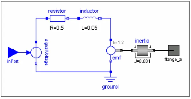
system assembly, exchange and simulation.
Modelica models are built up using a graphical model editor. For example, Figure 3.1
shows the Modelica model for a simple servo system. It is basically a directed graph
(includes feedback) with simple picto-graphics idealizing the components or
sub-systems interconnected. Modelica then sets up a text-based description of the topology
Figure 3.1. Modelica graphic of a simple servo system model (taken from Otter & Elmqvist, 2000).
[image:27.595.160.493.546.718.2]Figure 3.2. Modelica text-based model of the system in Fig. 3.1 (taken from Otter & Elmqvist, 2000).
of the system (see Figure 3.2). Furthermore, each component is defined by an
object-description diagram which encapsulates all the essential attributes needed for
simulation, which for an electrical motor includes such things as internal resistances and
inductances, voltage input and the driveshaft moment-of-inertia (see Figure 3.3). For
models to be constructed Modelica relies on a large library of system-building features
omprising the “Modelica base library” (Elmqvist et al, 1998). These include
arious interfaces are available to allow for Modelica model simulation via other
applications. Simulations driven by the MATLAB/Simulink (Elmqvist et al., 2004) or
Dymola (Dymola Homepage; Otter & Elmqvist, 2000) simulation engines are the most
prevalent. Otter & Elmqvist (2000) report the successful use of Modelica with Dymola
in a feasibility study at the Ford Motor Company, where 300 system states with some
260 000 equations were used to model vehicle dynamics.
c
mathematical functions, parameter type definitions, component interface type
definitions and component libraries across the various engineering domains able to be
modelled. Although aiming for component description standardization, these libraries
are static and thus limit the designer to the choice of components as captured during the
database population phases.
Chapter 4
MATLAB/Simulink: Evaluation for Virtual
Prototyping
MATLAB/Simulink forms the software development environment for which a
framework tool for VP is to be evaluated. These two complementary software tools are
examined for their suitability for engineering design and simulation via the
methodology of VP.
4.1 Design Basis for a Virtual Prototyping tool
A VP tool is a software application running on a personal computer or high-end
workstation. Although its functionality can be extended to the limits of the developer’s
imagination the VP of an engineering system requires three core functions, or modules,
that are required to respond to a designer’s request in real-time:
1.
component definition and visualization;
2.
component connection and system assembly; and
3.
system simulation, animation and feedback.
Figure 4.1. Context-level diagram for a typical VP application
4.2 Hardwa
s for a Virtual Prototyping Tool
Given the d i
tion 2.3) it is clear that
running on a computer allowing for user interaction. Therefore,
ent and the degree of code optimization for the tool.
rendering of a defined component, as well as to the monitor resolution on the host
re/Software Issue
ef nition for VP by Wang presented above (see sec
the VP tool is a program
issues are raised as to the ability of the software application and hardware platform to
allow the VP tool to adequately meet the system designer’s expectations for realistic
engineering system’s definition, presentation and simulation. These issues are, largely:
•
User response time;
•
Component/system visual resolution; and
•
Component/system visualization and animation.
The response time of the VP tool to the user’s commands will largely be in response to
the host processor speed and memory architecture, whether the tool is being run in a
heavy-laden multitasking environm
platform. The former is addressed at the VP tool development stage while the latter may
be addressed by providing the user with zoom functionality on the graphical
representation of the component/system to compensate for the model-scale to
screen-pixel resolution mapping.
omponent/system visualization refers to the perception features attributable to the
fers to the response of the
ssembled system when simulated. These will largely be influenced by, on the hardware
short for MATrix LABoratory, is a powerful highly-integrated
omputational engine developed by The MathWorks Inc, of the United States. It
and Simulink (see section 4.4), which is a graphical
bject-oriented style environment for system model static identification and dynamic
rformed via a series of
edicated window environments whose interactions are hidden from the user. These
C
component and assembled system while its animation re
a
side, the graphics card size and throughput buffering and, on the software side, the
graphics card drivers and whether such sophisticated 3-dimensional object shape,
colour-rnapping and light-rendering primitives are supplied as with, for example, the
OpenGL library.
4.3 MATLAB for Engineering Systems Design
MATLAB,
c
provides a relatively easy-to-use environment for the numerical computation and
visualisation of, largely, matrix-based problems via sequential command-line
instructions or more-sophisticated algorithms embedded in scripts. MATLAB
functionality is extended by a series of add-on toolboxes, which are essentially a suite of
application-specific algorithms,
o
simulation.
User-interaction and program development with MATLAB is pe
d
include a main command window, text editor for program development, workspace
window to view memory-resident variables and various windows for communications
with operating system services.
Visualisation in MATLAB is possible via a large suite of functions that generate and
customise windows, as well as graphics primitives which perform essential visual
perations such as, for example, plotting axes, setting lighting sources and
rogramming in MATLAB is performed via the MATLAB language, which employs
B environment, as opposed to being compiled and linked
s stand-alone programs resident and linked with the host operating system libraries.
Therefore, A
nerally be optimised for execution speed, though
its matrix/v t
for such. Program functionality is extended via
an Applica n
ch allows externally compiled C and
Fortran cod
LAB primitives.
, via its member fields. This can
en be multiply-defined for differing components of the same component family and
o
parameterising multi-dimensional data. Both three-dimensional and two-dimensional
visualisations are possible. User-interface controls such as push buttons and pull-down
menus provide the means to construct user-friendly GUI front-ends. The setting of
visualised object properties is handled via a sophisticated graphics system employing
symbolic handles that uniquely identify any graphics object. All visualisation functions
are optimised for speed and functionality given the presence of the OpenGL library on
the host platform.
P
C-like constructs and syntax. However, the language is used in scripts which are
interpreted within the MATLA
a
M TLAB code cannot ge
ec or operations are designed
tio Program Interface (API), whi
e to interact with MAT
In terms of the three core functions for VP addressed above (see section 4.1) MATLAB
is able to adequately address:
•
component definition;
•
component visualisation;
•
component interconnection; and
•
system assembly.
For engineering component definition MATLAB has a standard suite of fundamental
data structures, such as single-valued variables, multi-dimensional arrays/matrices and
structures, which can be designed and manipulated to store all relevant component
attributes. For example, a structure template can be designed to store all the attributes of
a component, such as spatial dimensions, weight, etc
stored in an array of s
store the definitions of one
type of component,
nent versus a “bolt” type of
component, where each successive array elem
e attributes of
the specific compone
y. Component attribute retrieval is
achieved first by array indexing to obtain the component structure and then by the
tructure field name for the relevant attribute. For example, using MATLAB notation,
t
ne defined by end-point vertices.
Patch
is a graphics function for creating patch
or engineering component interconnection a series of rules needs to be established and
examined bef
nnections to build an
ngineering system. These rules encapsulate the system definition in terms of its
tructures. That is, an array is used to
such as a “nut” type of compo
ent is a structure storing th
nt of that component famil
s
for the third valve component in a hydraulics system:
Valve(3).shape_type =
‘3_way_T’;
Valve(3).diameter =
10;
Valve(3).material =
‘aluminium’;
Valve(3).colour
= ‘grey-silver’;
Valve(3).weight
= 1.5;
…
For engineering component visualisation MATLAB has several powerful graphics
primitives to render either wireframe or solid-modelling representations of physical
models.
Line
is a graphics function for creating line graphics objects, which is a straigh
li
graphics objects, which are flat polygons defined by the coordinates of its vertices.
Depending on the scale of the rendering multiple patch objects can be grouped to give
the impression of a curved surface. Both lines and patches can be presented in
2-dimensional or 3-2-dimensional space, and can be set for various characteristics such as
colour, visibility, etc. Furthermore, patch objects can be rendered with lighting, thus
adding a sense of realism via variable shading appearances given a light source position,
and if OpenGL is present, can be altered for transparency, thus revealing hidden detail.
F
ore the designer can attempt component co
e
ConnectionRulesTable.Valve = [Pipe,Valve,Tap,…];
That is, in designing some hydraulics system, when the designer comes to connect a
valve” component MATLAB will examine the structure above for the “Valve” field
and determine, through its array value, that the only components to which it can connect
to, so a
e, a tap, etc. Once
this is
r through more
tables or through a series of MATLAB functi
ine the
o components to be connected and validate their fit in terms of the value of the
ned to store a component’s unique identifier as the
esigner connects relevant components together. That is, the evolving system is stored
to effectively manage
e designer’s inputs of data and commands through intuitive and easy-to-use
mouse-and keybo
-graphical rend
d the resulting assembled
system. Th
front-end. MATLAB in its
current form (ie. version 6.5) provides an adequate suite of user-interface controls
“
s to form a valid engineering system, is a pipe, another valv
verified more specific connection rules can be examined eithe
ons. These tables or functions exam
tw
specific geometric attributes characterising the fit. For example, for the interconnection
of a valve and pipe, using MATLAB notation:
If
( (Valve(valve_no).inlet_diameter = = Pipe(pipe_no).diameter) &&
(Valve(valve_no).thread_style = = Pipe(pipe_no).thread_style) &&
(Valve(valve_no).coeff_expansion < Pipe(pipe_no).coeff_expansion) && …)
…
For engineering system assembly MATLAB provides structure constructs for assembled
system definition and functions to manipulate the representative graphical objects. A
MATLAB structure may be defi
d
as an array of component identifiers as well as other parameters characterising the fitted
system. To manipulate the graphical object representation of a component MATLAB
identifies a graphics object through a graphics handle, which is a variable maintained to
uniquely identify the object, such as a patch or line object. All interrogation and visual
manipulation of the rendered object is done by accessing this handle. Therefore, the
designer can move the object through virtual space and alter its appearance by invoking
relevant functions on the handle.
As outlined above (see section 4.1) a VP tool must also be able
th
ard activated controls, as well as to provide a visual environment for the
ering of objects representing the components an
(UICs) tha
applications ru
ndows platforms. These standard UICs include, as
would be g
h the window title bar, for
•
radio buttons and check boxes to provide a choice amongst a small,
•
slider bars to accept numeric input within a fixed range;
•
edit text boxes to accept directly typed user input; and
•
floating menus attached to a graphics object or other UIC providing
environment in which time-based signals
an be formulated and routed through a maze of specific-action blocksets to simulate
t can be arranged to form a program interface very similar to those found on
nning on Microsoft Wi
rouped within a MATLAB-generated figure window:
•
menu and sub-menu items, usually underneat
standard application and host-system settings;
•
axes to display graphically-rendered output;
•
list boxes and pop-up menus to provide single/multiple choices across a
large range of values;
usually fixed, set of values;
•
push buttons to activate a choice or situation;
appropriate action choices.
Once arranged in an appropriate layout
3MATLAB then provides appropriate callback
functions whereby programmatic actions are linked to the UIC’s activation by the tool
user.
4.4 SIMULINK for Engineering Systems Simulation
Simulink
4is a software tool for the characterisation, simulating and post-simulation
analysis of system dynamic behaviour. It comes as an attachment to MATLAB and is
invoked via the MATLAB interface.
Simulink provides a graphical programming
c
system responses to changing inputs and internal states in accordance with discrete time
changes. MATLAB primitive and user-defined functions are invoked at each block in
sequence with the sample-time units which define the discretised passage of modelled
time. Time is ‘modelled’ because the execution of the simulation is in accordance with
the ability of both Simulink and the host hardware platform to solve the model states at
each time-step, which will vary accordingly.
The Simulink modelling environment is a graphical window where the user
interactively arranges blocks of appropriate functions. Lines, representing data
athways, are drawn between the blocks. The data present on any pathway can be
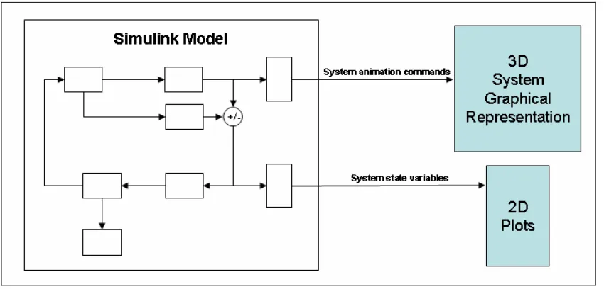
ble to adequately address all aspects of system simulation and, in conjunction with
ATLAB functions, animation of the simulated system and feedback to the
designer/user on the system’s performance during simulation. That is, the Simulink
program manages the solution of the model block equations at each time-step during the
simulation run while invoking MATLAB graphics primitives embedded in S-functions
so as to provide feedback on the state of the system at each time-step. This is idealized
in Figure 4.2 where a Simulink model is shown issuing animation commands to a
p
examined by various Simulink-defined tools or by user-written functions. The
S-functions are computer language descriptions of Simulink blocks, and can be written as
MATLAB functions acting on the data present on the input data path at each modelled
time-step as if called with the data in its input parameter list. The pathways carry data in
the form of a matrix, although this has been extended by Podium Technology to allow
for the transmission of user-defined MATLAB-style structure constructs.
In terms of the three core functions for VP addressed above (see section 4.1) Simulink is
a
[image:36.595.116.541.552.756.2]M
MATLAB figure window containing the 3-dimensional graphical representation of the
system and passing variables capturing the state of the simulation parameters to a
eparate MATLAB figure window for 2-dimensional plotting.
Simulink is widely used to model engineering systems behaviour under dynamic
conditions. For example, Johnsen and Eliasson (2004) use it to model wind-powered
turbines, Assanis et al. (1999) use it for diesel engine and driveline performance
analysis for heavy-duty trucks while Noskievi
č
(1999) uses it for the VR presentation of
fluid dynamic simulation.
Chapter 5
VirtProtoBench: A MATLAB/Simulink
Application for Feature-Based Virtual
Prototyping
As stated in the introduction the major outcome of the project is a software application
for engineering design evaluation based on the methodology of feature-based VP. It has
been termed “VirtProtoBench”, which is short for “Virtual Prototype Workbench”. This
title was chosen to reflect the nature of, and familiarity with, a designer/builder’s
workbench: the spatial area where, using a suite of tools, various parts are assembled
into some physical system and then tested for functionality and performance. The
application was developed, and is to be executed, wholly in the MATLAB/Simulink
environment.
In this chapter, VirtProtoBench is introduced in overview form before being discussed
in more detail in succeeding chapters. The project development environment and means
of application evaluation are considered.
5.1 An Overview of VirtProtoBench
•
10 *.fig, and associated *.m, files for the creation and management of all
major dialogue windows;
•
23 *.m files representing functions; and
•
4 *.m files for the management of, and output from, the one Simulink model
file run by the Simulink engine.
The *.m files are located in Appendix C. Many of these files include functions, prefixed
with “Local”, which are generally small and have functionality limited to the host
function file. This was done to limit the number of *.m files for file management and
maintenance purposes. The rationale for this may need to be re-evaluated in a possible
future release.
[image:39.595.116.539.413.737.2]The lone Simulink model file and *.fig files are not found in the Appendices as they are
non-ASCII format files. However, the graphical representation of the Simulink model
file is shown in Figure 9.1, while the various figures displaying the application dialogue
windows represent the instantiated *.fig files. The program is invoked at the MATLAB
e
irtProtoBench.fig,
and is presented in Figure 5.1
.
This is the main application GUI
r VP in section
.3). The design rationale for this main window, as well as overall program
response to user commands via
VirtProtoBench.fig
UICs,
VirtProtoBench.m
calls
appropriate i
coded UIC callback constructs. This
operational logic for VirtProtoBench is idealised in the data flow diagram-like
representat
admap’ of VirtProtoBench
behaviour
i
5.2 VirtProtoBench Development: Hardware/Software Environment
As in any engineering task the application developer must interact with a suite of
tools/instruments for product/system development. This research project is one largely
based on the writing of computer programs residing on a host computer platform.
Therefore, its resource requirements are largely hardware and software.
For computer hardware the author employed his personal Pioneer Soho model laptop.
For the purposes of this project its main features are:
•
Intel Pentium-4 3 GHz processor;
•
1 GB RAM;
•
60 GB hard drive;
•
128 MB Radeon 9600 Mobility graphics card; and
•
15" 1050x1400 pixel resolution TFT monitor.
command prompt via
VirtProtoBench.m
, which is associated with the figure fil
V
dialogue highlighting the designer’s workbench for component loading,
components-to-system assembly and visualization for components-to-system animation during the simulation run. It
represents, therefore, the “virtual world” for the designer as it is here that the model of
the system is constructed and interacted with (see Wang’s definition fo
2
functionality, is discussed further below.
In
d alogues and functions through the
Fi
gu
re
5.
2.
Dat
a fl
ow
di
ag
ram
-l
ik
e re
pr
esea
nt
at
ion o
f
Vi
rt
Pr
ot
oB
en
ch
ap
pl
icat
ion.
[image:41.595.115.491.161.678.2]The computer was not connected to a network so for data exchange purposes – for
example, printing on other networked machines - a USB drive and combined read-write
CD/DVD player/writer were utilized.
The main software tools loaded on the hardware outlined above and used for this project
are:
•
Microsoft Corporation XP Home operating system;
•
MATLAB/Simulink student version
56.5/5.0 Release 13;
•
Microsoft Corporation Internet Explorer
6; and
•
Microsoft Corporation Office Word;
MATLAB/Simulink was used as the software development environment for
VirtProtoBench. Internet Explorer was used for literature and VP marketplace product
research, while Word was used to compile this report.
5.3 VirtProtoBench Evaluation: Geared-Hoist Mechanism
In Appendix A the Project Specification outlines that a simple mechanical system will
be used to evaluate VirtProtoBench in terms of its utility as a VP tool. The mechanical
system chosen is the design and testing of a very simple geared-hoist mechanism. That
is, a system whereby a motor of fixed RPM-torque settings will be used to haul a load
vertically via a pair of interacting gears. In this evaluation of VirtProtoBench, the test
scenario is that of a mechanical systems designer who uses the tool to build and test a
geared hoist system. This will be done by importing relevant components, assembling
them into a geared-hoist system and then simulating the system for various load and
environmental conditions. In this way, VirtProtoBench is being used for the virtual
prototyping of a desired geared-hoist by a designer who essentially wants to examine
5 The student version has all the capabilities of the production version except that Simulink models are
limited in size/complexity to 300 blocks. Also, the product purchase agreement precludes use in an
employment /production environment. Version 7, Release 14 was purchased towards the end of the
current version development cycle, but was not used.
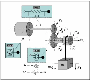
the marketplace for the appropriate components. This geared-hoist system is depicted in
Figure 5.3.
Figure 5.3 Idealized representation of a geared-hoist mechanism for load lifting
(taken from MathPros Homepage).
From the depiction it is clear that the mechanical system is composed essentially of the
following fundamental mechanical components:
•
a motor;
•
two interacting gears;
•
two shafts;
•
a spooler; and
•
a load.
echanical and electro-magnetic (eg for an electric motor) or chemical (eg for
diesel motor) in nature. However, for the purposes of the evaluation the motor will be
treated as a i
oil-filled gearb
needed.
The motor is, itself, a system, and, therefore, composed of many other components that
are both m
a
The listed com
solid-model re
nection and dynamic behaviour analysis.
These are
based component characterization. This is discussed further below.
The operation
aracterized by a large number of
physical in a
include:
t RPM;
•
heat generation and dissipation due to the motor power consumption and
nts; and
•
heat generation and dissipation due to the friction present between the
he geared-hoist mechanism acts as a singe-reduction gearbox. With reference to Figure
5.3 a p
eed produced
ponents possess characteristic features that are needed for wireframe or
presentations, system intercon
to be captured in appropriate file formats within the framework of a
of a geared-hoist mechanism is ch
ter ctions. This defines the dynamics of the system. At a large scale these
•
driving motor torque and rotational speed conversion through the
connected gears onto the driven gear/shaft/spooler sub-system;
•
the transmission of motor force and load weight forces as bending stress
at the interconnecting gear teeth;
•
the application of contact pressures at the gear tooth faces during
opposing gear tooth collision;
•
current and voltage consumption of the motor for variable loads at
constan
friction of internal compone
clashing gears.
These, and a large suite of other physical phenomenon, can be represented and predicted
by system equations. A system equation captures the essential nature of a physical
interaction by the input, output parameters and natural constants of the interaction. The
quantification of these values allows for the solution of the equation and, therefore, a
prediction of the output behaviour for the system. For the purposes of the current study
into the feasibility of VirtProtoBench the tool evaluation for dynamic behaviour is
limited to the first two physical interactions of this list: load-lifting kinematics and
tooth-bending forces.
5.3.1 Kinematics of Load-Lifting Force
T
by a m
e shaft, and rotates with the speed setting of the motor. This gear meshes with a
r radius, which rotates a spooler along a second common shaft.
ue of their
mechanical
provide greater torque, or
turning-his, in turn, transmits the amplified
inds a cable, connected to a load, at the same
also a reduction in rotational speed from the
namics of this interaction is
(I
driving/ r
driving2+ I
drivenG
2/ r
driven2+ m
load)
α
spooler=
I
driving= moment-of-inertia of driving components (kg.m
2);
= torque generated by motor (N.m);
α
spooler= rotational acceleration of spooler (rad.s
-1); and
The gear ra
number of driv
g gear teeth, or of their respective
radii, wher
the acceleration of the load and, thus, gives the lifting
te of the load. Furthermore, the term T
motorG / r
drivingmodels the lifting force applied to
on, and knowledge of the assembled
otor to lift a load. One gear, mounted on a shaft, is connected to the motor, via
th
second gear, of greate
These are referred to the driving and driven gears, respectively, by virt
connection to the driving force applied by the motor. The physics of
advantage apply at the common tooth interface to
force, along the shaft common to the driven gear. T
motor torque to the spooling drum which w
rotational speed as the driven gear. There is
gear of smaller radius to the gear of greater radius. The dy
expressible by the following system equation:
T
motorG / r
driving- m
loadg …… (1)
where,
I
driven= moment-of-inertia of driven components (kg.m
2);
r
driving= radius of driving gear (m);
r
driven= radius of driven gear (m);
G
=
gear-ratio;
m
load= mass of load (kg);
T
motorg
= gravitational acceleration on earth (ie ~9.81 m.s
-2).
tio is a non-dimensional quantity and is usually expressed as the ratio of the
en gear teeth to the number of drivin
e a ratio greater than one indicates torque amplification.
From equation (1) it is noted that, ignoring cable stretch, the acceleration of the loading
spooler
α
spooleris equivalent to
ra
component attributes, the designer can test the geared-hoist mechanism for various
behaviours, such as:
•
load acceleration and velocity depending on selected motor speed and
torque setting;
•
limit of load mass able to be lifted given the motor’s speed and torque
setting and cable breaking strain; and
•
acceleration of motor to maintain a constant load lifting rate.
The ability of VirtProtoBench to model certain aspects of this system kinematic
behaviour is evaluated below.
5.3.2 Dynamics of Gear Tooth-Bending Stress
The geared-hoist mec
ears to effect gear-ratio torque and rotational speed amplification/reduction. This
involves a complex interaction of forces at the interface of the connecting teeth, where
the tooth acts as a
m the tooth-to-tooth contact point to the
driven shaft. One
e applied on both the driving
and driven gear t
h
nto contact. It is at this interface that the
tangential forces,
are
transmitted, thereby tr
root
as a bending force
ress is at the tooth root, where the
tooth extends beyo
ference of the main gear wheel, and it is here that
the tooth may ben
have been devised to model this
complex interaction. The following AGMA system equation is used widely to model the
ending force present at a gear tooth in dynamic operation:
where,
hanism depicted in Figure 5.3 requires meshing between a pair of
g
lever transmitting torque fro
of these interactions is the tangential forc
oot faces as they come i
or torques, of the driving motor and loaded spooling drum
ansmitting stresses from the contacting tooth top to the tooth
. The point of greatest bending st
nd the outer circum
d or break off. Various equations
b
σ
= (W
tP
d/ F J) K
aK
sK
mK
v………... (2)
σ
= tooth bending stress;
W
t= maximum peak tangential force;
P
d= diametral pitch (ie number of teeth / gear pitch diameter);
K
a= application, or load, factor;
K
s= size factor;
K
m= load distribution factor; and
K
v= dynamic factor.
The factor constants have been determined from experience and can be found in
appropriate tables. Further information on these factors and other equations used can be
found in various gear manufacturer’s web sites and in Shigley et al. (2004).
Chapter 6
VirtProtoBench: GUI Design Methodology
A Graphical User Interface (GUI) is a crucial aspect of the VP design tool. Using a
bit-mapped screen display it provides the user with a sophisticated suite of graphical tools
for the purposes of decision-making, or application control, and for the display of
application output via mouse or keyboard selection. The arrangement of these tools
characterizes the “look-and-feel” of the application. The “look-and-feel’ of
VirtProtoBench version 1.1 is discussed.
For clarity of presentation the discussion of GUI design principles is presented h