i
UNIVERSITI TEKNIKAL MALAYSIA MELAKA
DEVELOPMENT OF PORTABLE MAGNETIC CLAMPING
This report submitted in accordance with requirement of the Universiti Teknikal Malaysia Melaka (UTeM) for the Bachelor’s Degree in Manufacturing Engineering
Technology (Process and Technology) with Honours
by
MUHAMAD SUHAIMI BIN JALIL B071410329
950101-08-5269
ii
DECLARATION
I hereby, declared this report entitled “Development of Portable Magnetic Clamping” is the results of my own research except as cited in references.
Signature :………
Name : MUHAMAD SUHAIMI BIN JALIL
iii
APPROVAL
This report is submitted to the Faculty of Engineering Technology of UTeM as a partial fulfillment of the requirements for the degree of Bachelor’s in Manufacturing Engineering Technology (Process and Technology) (Hons.). The member of the supervisory is as follow:
iv
ABSTRAK
v
ABSTRACT
vi
DEDICATIONS
vii
ACKNOWLEDGMENTS
I would like to express deepest gratitude to my supervisor Dr. Norfariza binti Abd Wahab for her full support, expert guidance, understanding and encouragement throughout my study and research. Without her incredible patience and timely wisdom and counsel, my thesis work would have been a frustrating and overwhelming pursuit. In addition, I express my appreciation to Mr Khahar bin Nordin for become the co-supervisor. His thoughtful question and comments were valued greatly.
Besides, not to forget technician who always help me solve some of the problem while doing my thesis who are Mr Azimin, Mr Zulkifli, Mr Hisyam, Mr Basri and all JTKP technician.
Thanks also go to my fellow friends at the Faculty of Technology Engineering of University Teknikal Malaysia Malaka. Special thanks go to my team who helped me throughout this academic exploration.
viii
TABLE OF CONTENTS
DECLARATION ii
APPROVAL iii
ABSTRAK iv
ABSTRACT v
DEDICATIONS vi
ACKNOWLEDGMENTS vii
TABLE OF CONTENTS viii
CHAPTER 1 1
INTRODUCTION 1
1.0 Background of the study ... 1
1.1 Problem Statement ... 2
1.2 Objectives ... 3
1.3 Scope ... 3
CHAPTER 2 4
LITERATURE REVIEW 4
2.1 Manufacturing Process ... 4
2.1.1 Conventional Machining 4
2.1.2 Advance Machining 9
2.2 Turning Process ... 14
ix
2.3 Clamping Method ... 16
2.3.1 Magnetic 17
2.3.2 Vacuum 19
2.3.3 Chuck 20
2.4 Effect of cutting parameters ... 21
2.4.1 Parameter 21
2.4.2 Surface roughness 22
CHAPTER 3 24
METHODOLOGY 24
3.1 Problem statement ... 25
3.2 Optimization design of magnetic chuck ... 26
3.2.1 Existing magnetic chuck 26
3.2.2 Improvement design for magnetic chuck 29
3.2.3 The comparison of the front part 32
3.2.4 Quotation of magnetic clamping 33
3.3 Machining ... 34
3.4 Evaluation of the product ... 36
3.4.1 Surface Roughness 36
CHAPTER 4 37
x
4.1 The changes of Magnetic Clamping application. ... 37
4.2 Machining ... 39
4.2.1 Rear part 39
4.2.2 Front part 42
4.2.3 Middle part 43
4.3 Assembly ... 44
4.4 Testing on milling machine ... 46
4.5 Surface roughness testing ... 50
4.6 Results ... 54
4.7 Problem and the solution ... 55
CHAPTER 5 59
CONCLUSION AND RECOMMENDATION 59
5.1 Summary Research ... 59
5.2 Recommendation for future study ... 60
REFERENCES 61
xi
LIST OF TABLES
Table 3. 1: Comparison between existing and the optimization on the front part . 32
Table 3. 2: Bil of material (BoM) ... 33
Table 4. 1: Parameter of cutting process ... 49
Table 4. 2: The value of surface roughness, Ra value ... 51
xii
LIST OF FIGURES
Figure 1. 1: Working principles of magnetic chucks ... 2
Figure 2. 1: Milling machine ... 5
Figure 2. 2: Overview milling operation ... 6
Figure 2. 3: (a) peripheral milling, and (b) face milling ... 6
Figure 2. 4: Tool drill ... 7
Figure 2. 5: Drill machine ... 7
Figure 2. 6: Grinding machine ... 8
Figure 2. 7: Schematic diagram of the Abrasive Water Jet Machiningprocess. ... 9
Figure 2. 8: Waterjet machine ... 10
Figure 2. 9: Schematic diagram of the electric-discharge machining process. ... 11
Figure 2. 10: EDM machine ... 11
Figure 2. 11: Schematic diagram of a transducer used in the ultrasonic machining (USM) process ... 12
Figure 2. 12: ultrasonic machine ... 12
Figure 2. 13: Schematic diagram of a laser beam process ... 13
Figure 2. 14 Lathe machine ... 14
xiii Figure 2. 16: Electro-permanent magnetic chucks ... 17
Figure 2. 17: Permanent magnetic round chuck ... 18
Figure 2. 18: Vacuum Clamping ... 19
Figure 2. 19: (a) Three-jaw chuck (b) 4-jaws chuck ... 20
Figure 2. 20: Graph for Ra ... 22
Figure 2. 21: Graph for Ry ... 23
Figure 2. 22:Graph for Rz ... 23
Figure 3. 1: Flowchart of methodology process. ... 24
Figure 3. 2: 3-jaw chuck that available at JTKP laboratory ... 25
Figure 3. 3: Front surface part ... 26
Figure 3. 4: Rear surface ... 27
Figure 3. 5: Assemble surface ... 27
Figure 3. 6: Side surface ... 28
Figure 3. 7: Arrangement of magnet ... 28
Figure 3. 8: PVC plate ... 29
Figure 3. 9: Pin and compression spring ... 29
Figure 3. 10: Adjustable screw... 30
Figure 3. 11: Combination of all the part in rear part ... 30
xiv Figure 3. 13: Holes for the lock pin ... 31
Figure 3. 14: lock pin ... 31
Figure 3. 15: Dimension of PVC plate ... 34
Figure 3. 16: Dimension of shaft... 34
Figure 3. 17: Holes for the lock and pins ... 35
Figure 4.1: (a) Chuck model GH-1440-3 (b) Chuck model Opti turn D420 ... 38
Figure 4.2: The magnetic chuck dimension ... 38
Figure 4. 3: Facing process ... 39
Figure 4. 4: Slot dimension ... 39
Figure 4. 5: Tool to lock the magnetic clamping on milling table ... 40
Figure 4. 6: The step to lock the magnetic clamping on the milling table ... 40
Figure 4. 7: Dimension of the mild steel plate for the rear part ... 41
Figure 4. 8: Dimension of hole position on the magnetic clamping ... 41
Figure 4. 9: The dimension of counter bore ... 41
Figure 4. 10: Grinding Process ... 42
Figure 4. 11: (a) raw material (b) The PVC plate after machining ... 42
Figure 4. 12: Facing process ... 43
Figure 4. 13: The narrow shaft and spring ... 43
xv Figure 4. 15: The step to assemble of all the part (a) All material are put on the table (b) Mild steel plate was put on the rear magnetic chuck (c) the allen bolt screw was put on the hole and was tighten (d) the combination of narrow pin shaft and spring was put on the hole (e) the PVC plate was put on the magnetic clamping and (f) the allen bolt screw was put on the PVC plate to lock it. ... 45
Figure 4. 16: Testing flatness process using dial gauge ... 46
Figure 4. 17: Workpiece testing on the magnetic clamping... 47
Figure 4. 18: The workpiece for experimental facing process ... 48
Figure 4. 19: Portable Surface Roughness Tester, SJ-401 ... 50
Figure 4. 21: The calibration process ... 51
Figure 4.22: Graph of depth of cut 0.1mm... 52
Figure 4. 23: Graph of depth of cut 0.2mm... 52
Figure 4.24: Graph of depth of cut 0.2mm... 53
Figure 4. 25: Comparison three depth of cut... 54
Figure 4. 26: The product of the magnetic clamping ... 55
Figure 4. 27: The magnet at “on” position (a). The magnet at “off” position (b) .. 56 Figure 4. 28: The process to unlock the material (a) push the narrow pin down (b) slide or rotate the PVC plate to unlock the material. ... 57
1
CHAPTER 1
INTRODUCTION
This chapter explain the overview of the study and the purpose of this study. The chapter includes the background of the study, problem statement, objectives that is expected to be achieved and the scope of the study that is going to be conducted.
1.0 Background of the study
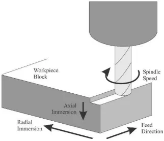
Milling is the machining process of using rotary cutters to remove material from a workpiece by advancing in a direction at an angle with the axis of the tool. It covers a wide variety of different operations and machines, on scales from small individual parts to large, heavy-duty gang milling operations.
Magnetic clamping usually used for fixturing of ferromagnetic material in perfection of switching functions. This magnetic clamping typically uses an electromagnet or permanent magnet to hold the material or workpiece during machining. (Felix and Melkote, 1999)
The main advantage for this magnetic clamping is to make it easy to attach and detach the workpiece and it able to clamp small and thin workpiece. Magnetic clamping can be applying in lathe and milling application. Also, it offers several advantages over conventional clamping methods such as three-jaw chucks and vice. Compared with the three-jaw place and vice, magnetic clamping produces very little flexible deformation of the workpiece and thus enable limited perspective and form specifications to take place.
2
[image:17.595.234.423.118.199.2]optimized and makes it possible to secure any ferrous materials placed on top of the system by organizing the place in a similar design.
Figure 1. 1: Working principles of magnetic chucks
This project is mainly focus on developing and improve the existing magnetic clamping for the lathe machine to the milling machine by using the entire convectional machine that available. The design of magnetic chuck is based on the previous development of the student and modified to the milling machine that available at JTKP Machining Technology Laboratory since the surface of magnetic clamping is flat. Furthermore, the magnet that will be use on this magnetic chuck is permanent magnet which it’s do not involve any electrical system. Then, for effectiveness a few analyses on the cutting parameter will take place.
1.1 Problem Statement
3 1.2 Objectives
The main objectives of this project is to develop a new magnetic clamping for milling machine The specific purposes for this project are summarized as follows;
i. To develop a magnetic clamping for milling machine
ii. To design the existing magnetic clamping for milling machine application.
iii. To analysis the results base on the developed magnetic clamping in term of surface roughness.
1.3 Scope
Scopes for this project is based on objectives that have stated and there are the several scopes that be carrying out:
i. Development of the magnetic clamping by using the convectional machine that available at the laboratory.
ii. Design and improve the existing magnetic clamping based on milling machine in the laboratory.
iii. Material that used for developing magnetic clamping are aluminium, mild steel, and PVC plate.
4
CHAPTER 2
LITERATURE REVIEW
This chapter explains about all findings obtained from many literature reviews, which may come from the internet, journals, article and books about the topic related to this study. This section includes findings about the overview of manufacturing process, turning machine, magnetic clamping method and effect of cutting parameters.
2.1 Manufacturing Process
Manufacturing processes are the stages through which raw materials are transformed into a final product. The manufacturing process starts with the creation of the materials from which the design is made. These materials are then modified through manufacturing processes to become the required product. Manufacturing processes can include treating (such as heat treating or coating), machining, or reshaping the material. The manufacturing process also includes tests and checks for quality assurance during or after the manufacturing, and planning the production process prior to manufacturing.
Manufacturing is the backbone of industrial community. The person that involved in industry must know the variety production procedures, materials being prepared, tools and apparatus for production with proper precautionary feature to avoid injuries. Beside above, a few consideration of workshops practices relating the basic working knowledge such as different technological innovation materials, resources, accessories, production procedures, uses of various testing instruments and inspecting products manufactured in the industry. (Singh, 2006)
2.1.1 Conventional Machining
5
conventional techniques that most frequently used are milling, edge trimming, drilling, turning, sawing, countersinking, and grinding. Conventional forming operations are performed with the energy from electric motors, hydraulics and gravity. Also, material joining is conventionally accomplished with thermal energy sources such as burning gases and electric arcs.
a) Milling process
A milling process is a machining operation in which a work part is fed past a rotating cylindrical tool with multiple cutting edges. For cutting operation, the workpiece is fed against the rotary cutter. As the workpiece moves against the cutting edges of milling cutter, metal is removed in form chips of trochoid shape. Machined surface is formed in one or more passes of the work. The work to be machined is held in a vice, a rotary table, a three jaw chuck, an index head, between centres, in a special fixture or bolted to machine table. The rotatory speed of the cutting tool and the feed rate of the workpiece depend upon the type of material being machined.
[image:20.595.254.383.584.734.2]Milling is the process of cutting away material by feeding a workpiece past a rotating multiple tooth cutter. The cutting action of the many teeth around the milling cutter provides a fast method of machining. The machined surface may be flat, angular, or curved. The surface may also be milled to any combination of shapes. The machine for holding the workpiece, rotating the cutter, and feeding it is known as the
6
Figure 2.2: Overview milling operation
(http://article.sapub.org/10.5923.j.ep.20130305.02.html)
Two forms of milling:
Figure 2.3: (a) peripheral milling, and (b) face milling
[image:21.595.147.492.361.535.2]7
b) Drilling Machine
Drilling is a commonly working as hole-making process that uses a drill as a cutting tool for producing round holes of various sizes and depths. Drilled holes may be subjected to additional operations for better surface finish and dimensional accuracy, such as reaming and honing, described later in this section. Drilling machines are intended for drilling holes, tapping, counter boring, reaming, and general boring operations. They may be classified into a large variety of types.(Madsen et al., 2016)
Drilling is the process of cutting or originating a round hole from the solid material. There are many ways of classifying drills. The tool (drill) and not the work piece is revolved and is fed into the material along its axis. For example, according to material, number and types of flutes, drill size, type of shank (straight or taper) and cutting point geometry etc. However the most common type of drill is the fluted drill shown in figure 2.4.
Figure 2.4: Tool drill
(http://engineeringhut.blogspot.my/2010/11/drilling-and-parts-of-twist-drill.html)
Figure 2.5: Drill machine
8
c) Grinding machine
Grinding Machines are also regarded as machine tools. A distinguishing feature of grinding machines is the rotating abrasive tool. Grinding machine is employed to obtain high accuracy along with very high class of surface finish on the work piece. However, advent of new generation of grinding wheels and grinding machines, characterized by their rigidity, power and speed enables one to go for high efficiency deep grinding (often called as abrasive milling) of not only hardened material but also ductile materials. (Gregory, 2001.)
[image:23.595.212.440.482.625.2]A grinding wheel consists of abrasive particles and bonding material. The bonding material holds the particles in place and establishes the shape and structure of the wheel. These two ingredients and the way they are fabricated determine the five basic parameters of a grinding wheel which is abrasive material, grains size, bonding material, wheel grade, and wheel structure. (Walker, 2000)
Figure 2.6: Grinding machine
9
2.1.2 Advance Machining
Non-traditional machining refers to advance machining that removes excess material by various technique involving mechanical, thermal, electrical, or chemical energy (or combinations of these energies). They do not use a sharp cutting tool in the conventional sense. (Walker, 2000)
a) Abrasive Water Jet Machining (AWJM)
[image:24.595.284.410.366.563.2]In abrasive-jet machining (AJM), material is removed by fine abrasive particles (aluminium oxide or silicon carbide) carried in a high-velocity stream of air, nitrogen, or carbon dioxide. The gas pressure ranges up to 120 lb/in2 (800 kPa), providing a nozzle velocity of up to 1,000 ft/s (300 m/s). Nozzles are made of tungsten carbide or sapphire. Typical applications are in drilling, sawing, slotting, and deburring of hard, brittle materials such as glass.
Figure 2.7 : Schematic diagram of the Abrasive Water Jet Machining process.