Dynamic fragmentation of rock clasts under normal compression in
sturzstrom
K. L. RAIT*, E. T. BOWMAN* and C. LAMBERT*
Sturzstrom are massive and catastrophic long run-out rock avalanches that occur in mountainous areas around the world. The dynamic fragmentation of rock clasts is considered by some to be a key mechanism leading to long run-out behaviour in sturzstrom, but details on the micromechanics of the process are lacking. It is hypothesised here that the high strain rates applied to rock clasts at depth within a sturzstrom in motion promote dynamic fragmentation. The kinetic energy of the fine material generated during fragmentation is postulated to decrease effective stress in the system via a disruption of load transfer between heavily loaded particles (i.e. the strong force network). This results in a reduction in effective friction within the system, leading to longer run-out or greater clast spreading than would otherwise occur. The discrete element method is utilised via PFC3D to investigate this behaviour by placing a single brittle cluster of particles within a cubic arrangement of non-breakable clusters, each of which is hexagonally close packed. This system is placed under varying normally applied strain rates while determining the effect of fragmentation rate on the behaviour of near particles. It was found that strain rate is directly related to the fragmentation process where, so long as a load is applied sufficiently quickly, particles will dynamically fragment rather than simply split or crush. The strain rate tests indicate an abrupt change from a static to dynamic regime where the process of bond breakage changes from fracture to explosive fragmentation and kinetic energy dominates frictional dissipation of energy.
KEYWORDS: discrete-element modelling; landslides; particle-scale behaviour
ICE Publishing: all rights reserved
INTRODUCTION
In steep mountainous areas around the world, pre-fractured ground masses and tectonic activity can be a precursor to long run-out rock avalanches or sturzstrom (Friedmannet al., 2003). Sturzstrom are catastrophic dry rock avalanches that travel substantially further horizon-tally than vertically (Hsu, 1975). A sturzstrom generally begins as a rock fall or rock slide before the debris material completely disintegrates during the high-speed run-out. Typically, the debris will be deposited with fine rock silt dominating the base, the central part consisting of disaggregated or jigsaw fractured rocks suspended within a silt-sized matrix and, near the surface, large angular boulders forming a ‘carapace’ (Dunning & Armitage, 2010). Throughout the deposit, the stratigraphy from the original failure site is retained (McSaveneyet al., 2000).
The behaviour of sturzstrom has been investigated by several researchers. Albert Heim was the first to suggest that the jostling flow of a sturzstrom was one of rearward blocks impacting forward blocks (Hsu, 1978). Hsu (1978) describes the possibility of Bagnoldian grain flow involvement where the flow behaviour is caused by impacts between grain layers as upper layers attempt to overtake lower layers in a sheared system (Bagnold, 1954). Other mechanical theories that have been suggested include air cushioning (Shreve, 1968) (since refuted by most researchers due to the occurrence of sturzstrom on the Moon and Mars), the formation of frictionite (Erismann, 1979), acoustic fluidisation (Melosh, 1983) and dynamic fragmentation (Davies et al., 1999).
Frictionite is not seen across all sturzstrom deposits and acoustic fluidisation may be related to fragmentation as acoustic waves are likely to be transmitted by boulder impacts (Melosh, 1983).
There are fundamental geomechanics questions regard-ing the ability of dynamic fragmentation to reduce friction between particles. Dynamic fragmentation can be described as a rock rupture event that occurs so rapidly under loading that multiple sites of failure appear simultaneously within the material and cause it to break apart into fragments. Davies & McSaveney (2008) suggest that, on a large scale, multiple fragmentation events in the basal area of a sturzstrom could create an isotropic dispersive pressure, like a pore pressure reducing effective stress and therefore friction. On a microscale, this dynamic behaviour may disrupt the strong force chains in the system as newly created fines disperse violently during a fragmentation event.
Both the effects of overburden load and shear are likely to influence the behaviour of a sturzstrom. The focus of this paper is specifically on the influence of overburden load on fragmentation. Dynamic fragmentation requires the rapid deposition of material in order to produce enough stress to overcome the strength of the underlying material (Grady, 1981). Beneath the carapace of a sturzstrom in motion, the combined impulsively applied load from multiple large boulders and surrounding material may provide enough pressure to fragment material towards the basal layer.
Using the discrete element method via PFC3D(Itasca, 2008), this paper presents a model of the fragmentation behaviour of a synthetic hexagonally close packed (HCP) material under different strain rates. Preliminary work performed by Rait & Bowman (2010) is followed and associated forces and stresses in the synthetic sturzstrom material are measured as the strain rate is varied.
Manuscript received 7 June 2012; first decision 24 July 2012; accepted 30 August 2012.
Published online at www.geotechniqueletters.com on 28 September 2012.
*University of Canterbury, Christchurch, New Zealand
SYNTHETIC MATERIAL TESTING
The initial failure phase of a sturzstrom is suggested as a rock fall or rock slide that then dynamically disintegrates as the material is compressed and sheared. Only the compres-sive process is examined here. The oedometric strain rate test is designed to investigate the breakage behaviour of a rock when confined between other boulders as disintegra-tion takes place. To explore this phenomenon, oedometric
tests in PFC3D were performed on five different but
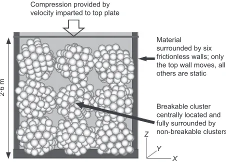
statistically similar HCP specimens (HCP1–HCP5); all specimens contain cubically arranged clusters with only the central cluster of each cube being breakable (as indicated in Fig. 1). Each cluster, of radius 0?5 m, was created at a designated central coordinate with all particles of radius 0?09 m (see material values in Table 1), following the process for HCP packing outlined by Robertson (2000) and randomly rotating each cluster. Flaws were introduced into each cluster by removing 20% of the particles as suggested by Cheng et al. (2003) and the particles were then bound together using contact bonds. The cubic arrangement of clusters was gently brought together using the confining walls until just in contact and the whole system was settled to equilibrium.
As the clusters were arranged using the same particle size, the difference between specimens rests solely on the random rotation of each cluster and the random placement of flaws. A suite of oedometric strain rate tests was performed on each specimen, ranging from quasi-static compression at 0?001 s21up to fast compression at 10 s21. The microscopic stresses and bond breakages in the breakable cluster were measured, along with system energies (kinetic, frictional, boundary and so forth) and overall wall stresses, to determine what effect, if any, a fragmenting boulder may have on a group of surrounding confined boulders. The microscopic stresses of the break-able cluster were measured via the summation of the mean and deviatoric stresses on each individual particle identified as belonging to the central cluster.
[image:2.595.64.290.584.746.2]RESULTS AND DISCUSSION
Figure 2 shows the microscopic deviatoric stressqplotted against microscopic mean stress p for HCP3 (with Fig. 3 indicating the maximum values reached for all specimens at 15% axial strain), while Fig. 4 shows the microscopic stress ratio (q/p) plotted against axial strain. The stress paths are similar in the early stages of the compression tests up to 6%
strain. For the lower strain rates, however, deviatoric stress
q reaches a peak of 12 MPa at an axial strain of 15%
whereas for the 10 s21strain rate,qrises to 46 MPa at the same strain. Figure 3 shows that this difference of maximumqat 15% axial strain occurs across all specimens, following the same behaviour as that of HCP3.
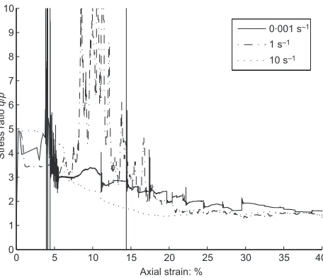
Figure 4 shows that, with an increase in axial strain, the stress ratio varies erratically for the 0?001 s21 strain rate tests, with peaks occurring throughout associated with large numbers of bonds being broken (Fig. 5). The first large breakage event at around 5% axial strain produces a drop in the stress ratio once the material settles during the next phase of overburden pressure increase. For the test at 1 s21, in which bond breakage occurs more gradually with axial strain from around 5%, breakage produces positive spikes in stress ratio, albeit less abrupt ones. In the 10 s21 strain rate tests though, we see a decrease in the stress ratio at around 6% axial strain, as breakage commences. The stress ratio then continues to decrease, remaining below that of the lower strain rate values until towards the end of the test where the stress ratios generally meet (Fig. 4). This suggests that the higher strain rate is producing a reduction in interparticle friction during the main breakage period, after which both lower and high strain rate tests become nearly equal. The axial strain point at which the behaviour becomes similar is a result of breakage occurring to the extent that rolling between particles may take place.
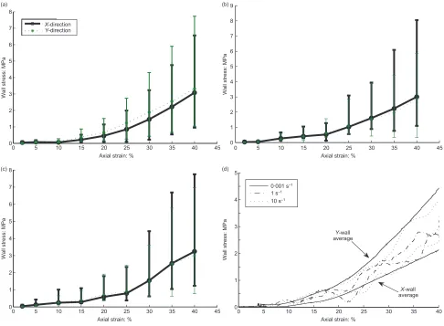
The wall stress response provides an interesting compar-ison between the 0?001, 1 and 10 s21 strain rates. Figures 6(a)–(c) show that the average wall stress taken across all tests for the X- and Y-directions (see Fig. 1) increases smoothly with strain and that there is little
Material surrounded by six frictionless walls; only the top wall moves, all others are static Compression provided by
velocity imparted to top plate
2
. 6 m
Z Y
X
[image:2.595.320.550.586.749.2]Breakable cluster centrally located and fully surrounded by non-breakable clusters
Fig. 1. Testing process of the cubic arrangement of HCP clusters under oedometric compression
Table 1.HCP material details
Parameter Value
Cluster radius: m 0?5
Particle radius: m 0?09 Particle density: kg/m3 2650 Particle friction coefficient 0?50 Particle normal and shear stiffness (central
cluster): N/m
46106
Normal and shear bond strength (central cluster): N
46103
Proportion removed for flaws: % 20
0 5 10 15 20 25 30
0 5 10 15 20 25 30 35 40 45 50
p: MPa
q
: MPa
0.001 s–1 1 s–1
10 s–1
variability when comparing the averages of X- and
Y-directions across all HCP specimens. The bars in Figs 6(a)– (c) show the range of wall stresses observed from specimen to specimen. As shown in Fig. 6(d) for an individual specimen, once breakage begins, the material becomes non-isotropic and therefore the wall stresses in the X- and Y -directions differ. This is also indicated by the lengthening of the range bars in Figs 6(a)–(c) at higher axial strain values. Figure 6(d) also shows that the 1 s21 and 10 s21 tests have the same general increase in wall stresses as the 0?001 s21test, but they now exhibit distinctive ‘wave-like’ patterns with strain. It appears that the wave-like patterns occur due to an interaction between the compression effect and the response of kinetic energy associated with the rate of compression. A damped wall stress response occurs as a result, slightly delayed relative to the kinetic energy peaks; the wider implications of this are yet to be confirmed.
Figure 7 plots the logarithm of peak kinetic energy against applied strain rate for all five specimens tested at all the strain rates considered. As strain rate increases, the peak kinetic energy does not begin to increase until a threshold of 1 s21 is reached, beyond which a dramatic increase emerges with increasing strain rate. Below a strain
rate of 1 s21, a similar and near-constant difference in peak kinetic energy develops between the specimens at increasing strain rates. By 10 s21 strain rate, it is difficult to discern the different data on the log plot. These results indicate that, at lower loading rates, the peak kinetic energy developed is dependent only on the initial state of the cluster (flaws and loading direction) and not on the loading rate, whereas beyond a rate of 1 s21, the peak kinetic energy is less influenced by the initial state and instead becomes a function of the loading rate.
The relationships between the varying energies that can be traced in PFC3D can be clearly seen in Fig. 8 for the 0?001 s21 and 10 s21 tests for HCP3. For the 0?001 s21 test, the increasing boundary work is converted into strain energy and frictional dissipation, with kinetic energy remaining very low (the 1 s21 strain rate and other tests are similar). At the 10 s21 strain rate, a very different behaviour emerges, with three distinct peaks in boundary work replicated in the kinetic energy and strain energy. At this high strain rate there is an abrupt change where the boundary work is now converted into strain energy and kinetic energy while frictional dissipation remains very low. The sudden ‘bursts’ of kinetic energy are not seen in any of the lower strain rates and appear to indicate the reaching of a dynamic or explosive regime. This is further clarified in Fig. 8(c), which shows similar initial bursts of kinetic energy from all specimens across all strain rates up to around 1% axial strain, followed by clearly differentiated kinetic energy maxima that are dependent on the strain rate of the test.
A comparison of breakage rate over axial stress for different strain rates is shown in Fig. 9 for three specimens. This indicates that the 10 s21strain rate test produced the most consistent breakage across the test, with the majority of breakage occurring between 5 and 25% strain (see also Fig. 5). The remainder of the test resulted in a few remaining breakages and movement of the particles to their final resting positions. In contrast, the 0?001 s21 strain rate test shows a few distinct peaks of high breakage rate as the material cleaves into fragments, but otherwise far less breakage by the test end at 40% strain. During these significant fragmentation events the released strain energy is dissipated by friction (see Fig. 8).
For low strain rates, Fig. 7 shows that the maximum kinetic energy produced is around two orders of magnitude less than that for the highest strain rate test. This suggests
0 5 10 15 20 25 30 35 40
0 1 2 3 4 5 6 7 8 9 10
Axial strain: %
Stress ratio
q
/
p
0.001 s–1
1 s–1
10 s–1
Fig. 4. Plot of stress ratio behaviour throughout the test for 0?001, 1 and 10 s21strain rates for HCP3
100
100
10-1 101 102
101
102
0.001 s–1
1 s–1
10 s–1
p: MPa
q
[image:3.595.48.275.59.248.2]: MPa
Fig. 3. Stress path maximum values for all HCP specimens for 0?001, 1 and 10 s21strain rates to 15% axial strain
0 5 10 15 20 25 30 35 40
0 20 40 60 80 100 120 140 160 180 200
Axial strain: %
Number of bond breakages
0.001 s–1
1 s–1
[image:3.595.300.531.65.244.2]10 s–1
[image:3.595.47.275.551.747.2]that, although applying a low strain rate can cause breakage in this particular synthetic specimen, the slow transfer of the forces allows for only the weakest bonds to break in the central cluster and these are represented by the large breakage events. The 1 s21strain rate test shows the majority of breakage occurring relatively early (with the
greatest rate of breakage occurring at 7% strain, albeit at a lower rate than for the 0?001 s21 strain rate) with few bonds left by 20% strain. The maximum kinetic energy is beginning to climb past that of the pseudo-static tests from 0?001 s21 to 0?1 s21. Together, these results suggest that rapid application of an overburden load can cause a large amount of damage to occur to a rock-type material with relatively little strain developed so long as it can overcome the strength of the material. The breakage behaviour combined with the impulsive kinetic energy in response to the boundary work and the oscillating wall stresses at higher strain rate suggest that, for the highest rate of strain, the central cluster has disintegrated via dynamic fragmentation.
CONCLUSIONS
One mechanism that may cause fragmentation in sturzstrom is the high-speed application of overburden load. The results of tests on an HCP agglomerate system under varying strain rates support the suggestion that dynamic fragmentation can reduce the mobilised friction q/pduring breakage. A high loading rate is seen to cause sustained breakage, which produces a much higher peak in kinetic energy compared with a low loading rate. For rapid loading, the stress ratio decreases quickly at the onset of breakage, suggesting that the explosive dispersion of the rapidly created fines reduces the effective stress and therefore friction when fragmentation occurs. Comparison between the test results at strain rates
0 5 10 15 20 25 30 35 40 45
0 1 2 3 4 5 6 7 8
(a) (b)
(c) (d)
Axial strain: %
Wall stress: MPa
data1 data2
X-direction
Y-direction
0 5 10 15 20 25 30 35 40 45
0 1 2 3 4 5 6 7 8 9
Axial strain: %
Wall stress: MPa
0 5 10 15 20 25 30 35 40 45
0 1 2 3 4 5 6 7 8
Axial strain: %
Wall stress: MPa
0 5 10 15 20 25 30 35 40
0 1 2 3 4 5
Axial strain: %
Wall stress: MPa
Y-wall average
X-wall average 0.001 s–1
[image:4.595.63.549.56.413.2]1 s–1 10 s–1
Fig. 6. X- andY- direction average wall stresses for strain rates of (a) 0?001 s21, (b) 1 s21and (c) 10 s21across all HCP specimens; range bars indicate minimum to maximum values observed. (d) Behaviour ofX- andY- direction average wall stresses for HCP3
108
107
106
105
104
103
10-3 10-2 10-1 100 101 102
10-4
Strain rate: s–1
Log of kinetic energy: Pa
HCP1 HCP2 HCP3 HCP4 HCP5
[image:4.595.61.292.554.746.2]0 5 10 15 20 25 30 35 40 −5
0 5 10 15 (a)
(c)
(b) 20× 10
4
× 105
Axial strain: %
Energy rate: J/time step
Friction Boundary Strain Kinetic
0 5 10 15 20 25 30 35 40
−2 0 2 4 6 8 10 12 14 16 18
Axial strain: %
Energy rate: J/time step
0 5 10 15 20 25 30 35 40
108
106
104
102
100
10-2
Axial strain: %
KE burst peak value: Pa
+
0.001 s–11 s–1
[image:5.595.45.534.56.472.2]10 s–1
Fig. 8. Energy behaviour for strain rates of (a) 0?001 s21and (b) 10 s21for HCP3. (c) Kinetic energy (KE) burst maxima across all HCP specimens for all strain rates
0 5 10 15 20 25 30 35 40
0 10 20 30 40 50 60 70 80 90 100 110
Axial strain: %
Breakage rate: bonds/time step
0.001 s–1
1 s–1
10 s–1
[image:5.595.138.439.549.756.2]from 0?001 s21to 10 s21shows the progression from static to dynamic loading and suggests that overburden rate is indeed important to the behaviour of sturzstrom. Future work will examine the influence of shearing rate within sturzstrom and will examine materials modelled on specific rock types.
Acknowledgements
The authors wish to acknowledge the support of the Department of Civil and Natural Resources Engineering at the University of Canterbury, and the New Zealand Earthquake Commission, as well as and the reviewers for their helpful comments.
REFERENCES
Bagnold, R. A. (1954). Experiments on a gravity-free dispersion of large solid spheres in a Newtonian fluid under shear. Proc. Royal Soc. London A Math. Phys. Sci.225, No. 1160, 49–63. Cheng, Y. P., Nakata, Y. & Bolton, M. D. (2003). Discrete
element simulation of crushable soil. Ge´otechnique53, No. 7, 633–641.
Davies, T. R. & McSaveney, M. J. (2008). The role of rock fragmentation in the motion of large landslides. Engng Geol.
109, No. 1–2, 67–79.
Davies, T. R., McSaveney, M. J. & Hodgson, K. A. (1999). A fragmentation-spreading model for long-runout rock ava-lanches.Can. Geotech. J.36, No. 6, 1096–1110.
Dunning, S. A. & Armitage, P. J. (2010). The grain-size distribution of rock-avalanche deposits: implications for
natural dam stability. InNatural and artificial rockslide dams
(Evans, S. G.et al. (eds)). Berlin: Springer, pp. 479–498. Erismann, T. H. (1979). Mechanisms of large landslides. Rock
Mech.12, No. 1, 15–46.
Friedmann, S. J., Kwon, G. & Losert, W. (2003). Granular memory and its effect on the triggering and distribution of rock avalanche events. J. Geophys. Res. Solid Earth 108, No. B8, 2380–2391.
Grady, D. E. (1981). Fragmentation of solids under impulsive stress loading.J. Geophys. Res.86, No. NB2, 1047–1054. Hsu, K. J. (1975). Catastrophic debris streams (sturzstroms)
generated by rockfalls.Geol. Soc. Am. Bull.86, No. 1, 129–140. Hsu, K. J. (1978). Albert Heim: observations on landslides and relevance to modern interpretations. In Rockslides and avalanches, Vol. I (Voight, B. (ed.)). Amsterdam: Elsevier, pp. 71–93.
Itasca (2008). Particle flow code in three dimensions. Minneapolis, MN: Itasca Consulting Group Inc.
McSaveney, M. J., Davies, T. R. & Hodgson, K. (2000). A contrast in deposit style and process between large and small rock avalanches. Paper presented at the 8th International Symposium on Landslides, Cardiff.
Melosh, H. J. (1983). Acoustic fluidization.Am. Sci.71, No. 2, 158–165.
Rait, K. L. & Bowman, E. T. (2010). Dynamic fragmentation in rock avalanches: A numerical model of micromechanical behaviour. Paper presented at the 7th European Conference on Numerical Methods in Geotechnical Engineering, Trondheim. Robertson, D. (2000). Computer simulations of crushable aggre-gates. PhD thesis, University of Cambridge, Cambridge, UK. Shreve, R. L. (1968). Leakage and fluidization in air-layer lubricated avalanches.Geol. Soc. Am. Bull.79, No. 5, 653–657.
WHAT DO YOU THINK?