platoon
.
White Rose Research Online URL for this paper:
http://eprints.whiterose.ac.uk/82985/
Version: Accepted Version
Article:
Jia, D, Lu, K and Wang, J (2014) A disturbance-adaptive design for VANET-enabled
vehicle platoon. IEEE Transactions on Vehicular Technology, 63 (2). pp. 527-539. ISSN
0018-9545
https://doi.org/10.1109/TVT.2013.2280721
eprints@whiterose.ac.uk https://eprints.whiterose.ac.uk/ Reuse
Items deposited in White Rose Research Online are protected by copyright, with all rights reserved unless indicated otherwise. They may be downloaded and/or printed for private study, or other acts as permitted by national copyright laws. The publisher or other rights holders may allow further reproduction and re-use of the full text version. This is indicated by the licence information on the White Rose Research Online record for the item.
Takedown
If you consider content in White Rose Research Online to be in breach of UK law, please notify us by
A Disturbance-Adaptive Design for
VANET-Enabled Vehicle Platoon
Dongyao Jia, Kejie Lu, Jianping Wang
Abstract—In highway systems, grouping vehicles into platoons
can improve road capacity and energy efficiency. With the advance of technologies, the performance of platoons can be further enhanced by vehicular ad-hoc network (VANET). In the past few years, many studies have been conducted on the dynamics of VANET-enabled platoon under traffic disturbance, which is a common scenario on a highway. However, most of them do not consider the impact of platoon dynamics on the behaviors of VANET. Moreover, most existing studies focus on how to maintain the stability of a platoon, and do not address how to mitigate negative effects of traffic disturbance, such as uncomfortable passenger experience, increased fuel consumption, and increased exhaust emission. In this paper, we will investigate the dynamics of VANET-enabled platoon from an integrated perspective. In particular, we first propose a novel
disturbance-adaptive platoon (DA-Platoon) architecture, in which a platoon
controller shall adapt to the disturbance scenario and shall consider both VANET and platoon dynamics requirements. Based on a specific realization of the DA-Platoon architecture, we then analyze the traffic dynamics inside a platoon and derive desired parameters, including intra-platoon spacing and platoon size, so as to satisfy VANET constraints under traffic disturbance. To mitigate the adverse effects of traffic disturbance, we also design a novel driving strategy for the leading vehicle of platoon, with which we can determine the desired inter-platoon spacing. Finally, we conduct extensive simulation experiments, which not only validate our analysis but also demonstrate the effectiveness of the proposed driving strategy.
Index Terms—Vehicle platoon, traffic disturbance, vehicular
ad-hoc networks (VANET), platoon dynamics, platoon parame-ters, driving strategy, disturbance-adaptive platoon (DA-Platoon), Intelligent Driver Model (IDM).
I. INTRODUCTION
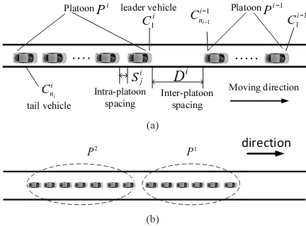
When traveling on a highway, a group of consecutive vehicles can form a platoon, in which a non-leading vehicle maintains a small distance with the preceding one, as shown in Fig. 1. In the literature, it has been shown that there are many benefits to drive vehicles in platoon patterns [1], [2]. First, since adjacent vehicles are close to each other, the road
capacity can be increased and the traffic1 congestion may be
decreased accordingly. Second, the platoon pattern can reduce the energy consumption and exhaust emissions considerably
Dongyao Jia is with the Department of Computer Science, City University of Hong Kong, China. Kejie Lu is with the Department of Electrical and Computer Engineering, University of Puerto Rico at Mayag¨uez, PR, USA. Jianping Wang is with the Department of Computer Science, City University of Hong Kong, China.
This work was supported in part by the National Science Foundation of China (No. 61272462), and by the CityU Project No. 9231101. This work was also supported in part by NSF Award CNS-0922996.
Manuscript was submitted on February 19, 2015.
1In this paper, “traffic” is limited to the context of vehicle transportation.
Platoon i−1
P
Platoon i
P
Moving direction
i
D
ini
C
i j
S
1 1
− −
i ni
C
Inter-platoon spacing Intra-platoon
spacing tail vehicle
leader vehicle
i
C1
1 1
−
i C
(a)
direction
2
P 1
P
(b)
Fig. 1. (a) An example of platoon with platoon parameters, (b) Two large adjacent platoons with small inter-platoon spacing
because the streamlining of vehicles in a platoon can minimize air drag. Third, with the help of advanced technologies, driving in a platoon can be safer and more comfortable.
To facilitate platoons, two important technologies have been introduced in the past decade, specifically, autonomous cruise control (ACC) [3] and vehicular ad-hoc network (VANETs) [4]–[6]. The ACC system with laser or radar sensors can obtain the distance to the preceding vehicle and can regulate the movements of individual vehicles in a platoon. On the other hand, VANET not only can help to form and maintain a platoon, but also can enable a vehicle to exchange traffic in-formation with neighboring vehicles or infrastructures, which may improve traffic safety, efficiency, and comfortability.
In the past few years, a lot of studies have been conducted on such VANET-enabled platoons [7], which can be classified into two categories. In the first one, studies mainly address VANET issues, such as VANET connectivity, data dissem-ination protocol and routing techniques, MAC scheduling, etc., [8]–[10], based on an existing platoon. In the second category, most studies are about the traffic dynamics control and performance optimization by managing and controlling platoons [1], [11]–[25], with the help of an existing VANET. In this paper, we assume that a VANET has already been set up and we will investigate the dynamics of a VANET-enable platoon system.
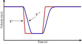
Specifically, we investigate the dynamics of VANET-enabled platoon under traffic disturbance, which is a common scenario on a highway. As an example, Fig. 2 illustrates a typical disturbance scenario [16], where the leading vehicle
[image:2.595.328.544.225.385.2]Time (s)
Velocity (m/s) v
low
v
stb
[image:3.595.122.227.105.161.2]A
Fig. 2. A typical disturbance scenario.
WůĂƚŽŽŶ
ŝƐƚƵƌďĂŶĐĞ
LJŶĂŵŝĐƐ
WůĂƚŽŽŶ
ŽŶƚƌŽůůĞƌ
• ƌŝǀŝŶŐƐƚƌĂƚĞŐLJ
ĞƐŝŐŶKďũĞĐƚŝǀĞƐ
• ŽŶƐƚĂŶƚŝŶƚƌĂͲƉůĂƚŽŽŶƐƉĂĐŝŶŐ
• ŽŶƐƚĂŶƚƚŝŵĞŚĞĂĚǁĂLJ
• ŽŶƐƚĂŶƚǁĞŝŐŚƚĞĚŝŶƚƌĂͲƉůĂƚŽŽŶƐƉĂĐŝŶŐ
(a)
ͲWůĂƚŽŽŶ
ͲWůĂƚŽŽŶ
ŽŶƚƌŽůůĞƌ
• WůĂƚŽŽŶƉĂƌĂŵĞƚĞƌƐ • ƌŝǀŝŶŐƐƚƌĂƚĞŐLJ
LJŶĂŵŝĐƐ
ĞƐŝŐŶKďũĞĐƚŝǀĞƐ • ^ƚĂďůĞsEdƚŽƉŽůŽŐLJ • ŽŵĨŽƌƚĂďůĞƉĂƐƐĞŶŐĞƌĞdžƉĞƌŝĞŶĐĞ • ZĞĚƵĐĞĚĞdžŚĂƵƐƚĞŵŝƐƐŝŽŶ • ZĞĚƵĐĞĚĨƵĞůĐŽŶƐƵŵƉƚŝŽŶ
[image:3.595.95.253.196.444.2](b)
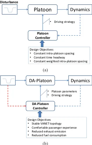
Fig. 3. (a) The platoon dynamic system in existing studies, (b) The
DA-platoon dynamic system.
to a lower velocity vlow, and then maintains this speed for
a period of time before accelerating to the original speed. Clearly, we can consider a formed platoon as a system and regard a disturbance scenario as the input and traffic dynamics as the outputs, as shown in Fig. 3(a).
In practice, such a system may be unstable under certain dis-turbance scenarios. Therefore, in the literature, most existing studies on VANET-enabled platoon system were focused on maintaining the stability of platoon. Typically, they address the design and evaluation of the platoon controller, which specifies the driving strategy based on the observed traffic dynamics with different design objectives.
For instance, for intra-platoon dynamics, [19] assumed that each vehicle only has the relative position to its preceding vehicle, and assumed that a predecessor-following control strategy is applied. For such a system, the authors stud-ied disturbance propagation in a platoon and showed error amplification of intra-platoon spacing. To maintain constant intra-platoon spacing, predecessor-leader control strategy was proposed in [16] and [18], wherein each vehicle should get information from both its preceding vehicle and the platoon leader. In [21], the constant-time headway policy was applied while each vehicle can get the kinematics status (location, ve-locity, acceleration, etc.) of the preceding vehicle via VANET. Although existing studies are important to the applicability
of platoon, there are still many open issues. First, it is unclear how platoon dynamics can affect the behaviors of VANET during disturbance. For example, the acceleration of a preceding vehicle can enlarge the gap between vehicles or the distance between adjacent platoons, which may lead to not only platoon splitting but also unreliable V2V communication with high packet loss and large delay. On the other hand, the deceleration of the preceding vehicle may lead to the merger between adjacent platoons with close distance, as shown in Fig. 1(b).
The second issue is that most existing studies focus on how to maintain the stability of a platoon (e.g., constant intra-platoon spacing), and do not address how to mitigate negative effects of traffic disturbances, such as uncomfortable pas-senger experience, increased fuel consumption, and increased exhaust emission. In practice, traffic disturbances could cause frequently and sharply accelerating and decelerating, which results in not only the uncomfortable driving patterns, but also significant fuel consumption and exhaust emissions [17]. In this case, it will be desirable to utilize the capability of VANET to mitigate such negative effects.
To address these issues, in this paper, we investigate the dynamics of VANET-enabled platoon from an integrated per-spective. In particular, we first propose a novel disturbance-adaptive platoon (Platoon) architecture, with which a DA-Platoon dynamic system can be defined. As illustrated in Fig. 3(b), the DA-Platoon system includes a controller that shall adapt to the disturbance scenario and shall consider both VANET requirements and platoon dynamics requirements.
Our main contributions in this paper are listed as follows:
1) We propose a novel disturbance adaptive platoon (DA-Platoon) architecture in which we consider both traffic dynamics under disturbances and the constraints due to VANET communications.
2) We investigate the characteristic of DA-Platoon dynam-ics under disturbance. Based on the analytical model, we derive the desired DA-Platoon parameters that can satisfy both traffic dynamics requirements and VANET connectivity requirements.
3) To mitigate the negative effects of traffic disturbances, we propose a novel driving strategy for the leading vehicle of a platoon, with which we can obtain a desired inter-platoon spacing that can help to achieve the desired traffic dynamics and that does not violate the VANET constraints in disturbance scenarios.
WůĂƚŽŽŶ DĂŶĂŐĞŵĞŶƚ
džŝƐƚŝŶŐdƌĂĨĨŝĐ
&ůŽǁ WůĂƚŽŽŶ
WůĂƚŽŽŶDĂŶĂŐĞŵĞŶƚ ^ƚƌĂƚĞŐLJ
ĞƐŝŐŶKďũĞĐƚŝǀĞƐ • DĂdžŝŵŝnjŝŶŐƉůĂƚŽŽŶƐŝnjĞ
• DĂdžŝŵŝnjŝŶŐƚŚĞůŝĨĞƚŝŵĞĂŶĚƐƚĂďŝůŝƚLJŽĨƉůĂƚŽŽŶ • ĐĐĞůĞƌĂƚŝŶŐƉůĂƚŽŽŶŝĚĞŶƚŝĨŝĐĂƚŝŽŶ • ĐĐĞůĞƌĂƚŝŶŐƉůĂƚŽŽŶĨŽƌŵĂƚŝŽŶ
WůĂƚŽŽŶŵĂŶĂŐĞŵĞŶƚƉƌŽƚŽĐŽů
• ĂƐĞĚŽŶĐůƵƐƚĞƌŝŶŐŝŶDEd
• &ŝŶŝƚĞͲƐƚĂƚĞŵĂĐŚŝŶĞŵŽĚĞů • &ŝůƚĞƌĞĚŵƵůƚŝĐĂƐƚ
• DĞŵďĞƌƐŽĨƉůĂƚŽŽŶ
[image:4.595.85.262.105.251.2]• ZŽůĞŽĨǀĞŚŝĐůĞƐ
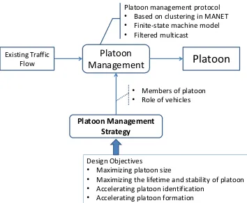
Fig. 4. The platoon management system in existing studies.
II. RELATEDWORK
In this section, we first discuss how to manage platoons with the help of VANET. We then elaborate on the platoon dynamics in related work. In particular, we classify existing studies into two groups: intra-platoon and inter-platoon.
A. The Platoon Management System
In the literature, some studies assume that an existing platoon is formed naturally [13], while others consider platoon formation, merging, splitting with the help of VANET [26]. Based on existing studies, we illustrate the platoon manage-ment system in Fig. 4. As shown in this figure, existing studies can be distinguished according to the platoon management protocol and the platoon management strategy. The platoon management protocol can enable vehicles to communicate with one another. The platoon management strategy deter-mines the members of a platoon and the roles of individual vehicles based on various design objectives.
In terms of platoon management protocol, a filter-multicast protocol was proposed in [12] to realize dynamic platoon-ID allocation, platoon dynamic formation and management. A finite-state machine model was developed in [14] to de-scribe the operating process of the platooning protocol. In a more general sense, many existing protocols for clustering in mobile ad hoc networks (MANETs) can be applied to support platoon management. For example, Tarik Taleb et al. presented a dynamic clustering mechanism to form clusters with a cooperative collision-avoidance (CCA) scheme [6].
In terms of platoon management strategy, [12] categorized vehicles into three roles, master, member and normal vehicle, according to their relative positions and communication range, and then formed platoon based on the roles of nearby vehicles. In [14], the main objective is to quickly identify the platoon, where a prediction scheme was designed to accelerate platoon formation when some vehicles are moving towards a different direction (i.e., platoon splitting). In [1], the objectives included (1) to maximize the platoon size and (2) to maximize the life time of platoon. To reach these goals, the authors designed a scheme to group vehicles based on their destination at the entrance ramp.
Compared to existing studies on platoon management sys-tem, our study can be considered as a platoon management
strategy, in which our objective is to satisfy both VANET connectivity requirements and traffic dynamics requirements. Therefore, existing platoon management protocols can be used to form a platoon with the desired platoon parameters.
B. Intra-Platoon Dynamics
For a single platoon, many previous studies have been focused on the intra-platoon dynamics, which describe the transient and steady responses of a platoon, including intra-platoon spacing, velocity and acceleration trajectory of each vehicle, etc., under certain spacing policy and control strategy [18]–[20].
In [19], the authors analyzed disturbance propagation in a platoon and showed error amplification of intra-platoon spac-ing under a predecessor-followspac-ing control strategy, in which each vehicle only has the relative position to its preceding one. To maintain constant intra-platoon spacing, predecessor-leader control strategy [18] is proposed wherein each vehicle should get information from both its preceding vehicle and the platoon leader. To realize this strategy, the cooperative ACC (CACC) has been proposed to maintain the stability of a given platoon [15], [16], [21]–[23].
Theoretical and experimental results showed that V2V com-munications enable driving at small inter-vehicle distances while string stability is guaranteed. A general design of the CACC system has been proposed in [21] adopting constant-time headway policy in a decentralized control framework. In [16], it has been shown that the constant-spacing policy with V2V communications can increase the traffic throughput. A new platoon control method, called consensus control, is proposed in [23], where vehicles are deployed to converge the weighted intra-platoon spacing to a constant and maintain a constant platoon length at the same time.
Normally a vehicle has two operational modes: spacing control mode and speed control mode. To get an optimized traffic flow performance, it is critical for the vehicle to design a suitable switching logic that decides when to switch between the two operational modes. In [25], a switching strategy is proposed for ACC-equipped vehicles in platoon, which designs a constant-deceleration spacing control model by way of Range (R) vs. Range-rate diagram.
Despite the potentials, it is very challenging to apply VANET for intra-platoon control because it is still difficult to guarantee reliable communications in realistic scenarios, where transmission delay and errors can occur due to the mobility of vehicles, the transmission contention, and the topology change in VANET. Therefore, in this paper we only apply ACC for intra-platoon control. In particular, we apply the Intelligent Driver Model (IDM), which is essentially based on the constant-time headway control.
C. Inter-Platoon Dynamics
DA-Platoon Moving direction
tail vehicle leader vehicle
common vehicle
member vehicle
[image:5.595.68.282.107.197.2]relay vehicle
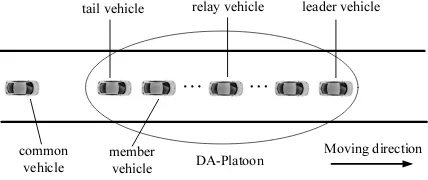
Fig. 5. DA-Platoon architecture
for platoon merging and splitting actions. The authors in [24] investigated inter-platoon dynamics, where smooth platoon merging is regulated by a proportional controller which sup-plies an acceleration to the leading vehicle of a following platoon that is proportional to the inter-platoon spacing. When two platoons move close to a certain distance, the leading vehicle of the following platoon will switch to the intra-platoon spacing control strategy. In [15], it has been demonstrated that significant disturbance can propagate from a preceding platoon to the following one if two large adjacent platoons have small inter-platoon spacing, as illustrated in Fig. 1 (b).
Clearly, how the merging or splitting affect the VANET has not been a major concern. For instance, if two large platoons merge into a “huge” one after the disturbance, serious VANET connectivity problems may occur due to unreliable multi-hop data transmission. Note that V2V communication in such huge platoon is more vulnerable to uncertain transmission delay in VANET with contention-based access mechanism [27], which could cause vital results in critical safety applications.
In this paper, we consider that adjacent platoons should maintain suitable inter-platoon spacing. To this end, we design a novel platoon architecture that can alleviate the traffic disturbance and can efficiently enable cooperative strategy among consecutive platoons, which will be discussed in the next section. In Section V, we will also propose a new driving strategy for the leading vehicle of platoon, whose main idea is to allow the leading vehicle to react to the disturbance as soon as necessary, which has not been reported in the literature.
III. THEDA-PLATOONARCHITECTURE
In this section, we first propose a general DA-Platoon architecture. We then specify one particular instance to be investigated.
A. The DA-Platoon Architecture
Although there are many existing studies on the platoon dynamic system under disturbance, we note that there are still many open issues, including the impact of platoon dynamics on VANET behaviors and how to mitigate negative effects due to traffic disturbance. To address these important issues, we propose a new disturbance adaptive platoon (DA-Platoon) architecture, where we jointly consider VANET requirements and traffic dynamics requirements under disturbances.
Fig. 5 illustrates a general architecture of DA-Platoon. In this architecture, vehicles can communicate through VANET.
Vehicles of one platoon share a unique DA-Platoon identifica-tion (ID). According to the spatial posiidentifica-tion and funcidentifica-tionalities, members in a platoon can be classified into four roles: leader, relay, tail, and member.
• Leader: The leader is the leading vehicle in the platoon. It is responsible for creating and managing the platoon, e.g., identifying and periodically broadcasting the DA-Platoon ID, deciding whether a vehicle can join the platoon and then assigning role to the vehicle, and determining whether a platoon shall be split or whether two platoons shall be merged into one.
• Tail: The tail vehicle locates at the end of a platoon. It is responsible for communicating with the following vehicles, especially the leader of the next platoon.
• Relay: The relay vehicles act as data-forwarding nodes in a multi-hop VANET environment. In this way, the infor-mation from the leader can be efficiently disseminated to all vehicles in a platoon.
• Member: Other member vehicles are regular vehicles that receive information from the relay and shall follow a specified driving strategy.
With such a design, the topology of VANET becomes simpler because a backbone is formed by the leader, relays, and tail. Moreover, the few relays can efficiently determine the transmission schedule of each vehicle in the platoon, which can significantly improve the reliability of VANET communications.
As noted in Section II, we consider our design as a platoon management strategy. Therefore, we can apply existing platoon management protocols to facilitate the implementation of the management strategy.
B. Specification for A DA-Platoon Scenario
1) Platoon Parameters: To facilitate further discussions, we let intra-platoon spacing be the distance between adjacent vehicles in the same platoon, and we let inter-platoon spacing be the gap between the tail of a preceding platoon and the leader of the next platoon. Based on these definitions, we can define platoon parameters, as illustrated in Fig. 1(a), wherePi
means thei-th platoon,Ci
j denotes thej-th vehicle inPi,Sji
denotes the intra-platoon spacing betweenCi
j−1 andC
i j, and
Di is the inter-platoon spacing between Pi−1 andPi.
2) Knowledge of Traffic Information: To acquire traffic information, we assume that each vehicle is equipped with global positioning system (GPS) and other sensors that can collect all needed local information from neighbors, including acceleration, velocity, location, direction, etc. In addition, ACC and VANET components are equipped on each vehicle.
TABLE I
NOTATIONS
a the maximum acceleration
ai
j the acceleration ofCji
b the comfortable deceleration
Ddes the desired inter-platoon spacing
Di the inter-platoon spacing betweenPi−1andPi
DM T R the fixed minimum transmission range
d0 the minimum inter-platoon spacing (at standstill)
li the length of platoonPi
L0 the length of a vehicle
ni the number of vehicles in platoonPi
Si
j intra-platoon spacing betweenCji−1andC
i j
s0 minimum intra-platoon spacing (at standstill)
T0 the desired time headway
v0 the maximum speed
vi
j the velocity ofCji
xi
j the position ofCji
4) The Platoon Driving Strategy: Due to strong interaction among adjacent vehicles within the same platoon, the most common vehicle mobility model is the car-following model, which can effectively describe ACC-equipped platoon dynam-ics [28]. In this paper, we consider that all vehicles, except the leaders, move according to a car-following model.
For the leader of a platoon, on the other hand, it is important to maintain suitable inter-platoon spacing between two adjacent platoons in some cases. Therefore, the leader is supposed to be controlled by a certain strategy with the help of V2V communications, which will be addressed in section V. In summary, different from traditional platoon or cluster proposed for VANET, our DA-Platoon takes into consideration both the vehicle mobility and VANET connectivity, which will be demonstrated in the following sections.
IV. INTRA-PLATOONDYNAMICS ANDPARAMETERS
In this section, we first present key assumptions regarding DA-Platoon. We then introduce the Intelligent Driver Model (IDM), with which we further investigate the correspond-ing platoon dynamics. Based on the understandcorrespond-ing of the dynamics, we then investigate platoon parameters, including intra-platoon spacing and platoon size, under consideration of VANET connectivity in disturbance scenarios.
A. Assumptions and Notations
1) Identical vehicle: To simplify the analysis, we assume that a DA-Platoon consists of identical vehicles driving on a single lane (which means overtake is not allowed for the vehicle).
2) Disturbance Scenario: In this paper, we consider the classic “stop and go” scenario [4] for traffic disturbance. Specifically, the disturbance scenario is defined as the velocity trajectory ofCi
1, which initially changes its velocity fromvstb
to a lower velocity vlow, then maintains at vlow for a period
of time, and finally resumes tovstb, as shown in Fig. 2. Note
that the semantics of disturbance is different from the small perturbation in vicinity of the velocity vstb.
3) Notations: To facilitate further discussions, important notations are summarized in table I, where variables have been sorted according to the alphabetic order. Note that, for convenience, the platoon index is skipped in the rest of this section because we are discussing a single platoon.
B. The Intelligent Driver Model (IDM)
In general, a car-following model can be described as a
function f(S, v,∆v), which determines the acceleration of a
vehicle at timet by:
aj(t) =
dvj(t)
dt =f(Sj(t), vj(t),∆vj(t)), (1)
where the acceleration of vehicle Cj depends on its own
velocityvj(t), the intra-platoon spacingSj(t), and the velocity
difference∆vj(t) :=vj(t)−vj−1(t)to the preceding vehicle.
To implement the car-following model in a vehicle, practically numerical integration should be executed on vehicle by the following equations [29]:
vj(t+ ∆t) =vj(t) +aj(t)∆t (2)
xj(t+ ∆t) =xj(t) +vj(t)∆t+
1
2aj(t)∆t
2
(3)
wherexj is the position of Cj and the intervals∆tis called
update time. For ACC-equipped vehicles, these operations are executed automatically and normally the update time can be set to a small value (about 100ms order). Therefore, we can regard DA-Platoon dynamics as strictly conforming to the time-continuous car-following model.
In this paper, we apply a typical car-following model for ACC-equipped vehicle, knows as the Intelligent Driver Model (IDM) [30], which is based on the stimulus-response approach and can be expressed as follows:
S∗
j(t) =s0+vj(t)T0+
vj(t)∆vj(t)
2√ab (4)
aj(t) =a
h
1−vjv(t)
0
4
−S ∗
j(t)
Sj(t)
2i
(5)
whereS∗
j(t)is the desired gap to the preceding vehicle and
the other parameters can be found in Table I. In the IDM, the instantaneous acceleration consists of a free acceleration on the road where no other vehicles are aheada[1−(vj(t)/v0)4],
and an interaction deceleration with respect to its preceding
vehicle−a(S∗
j(t)/Sj(t))2.
Fig. 6 illustrates traffic dynamics of DA-Platoon consisting of 10 vehicles implemented by the Simulation of Urban Mobility (SUMO) [31] traffic simulator.
50 100 150 200 250 5
10 15 20 25 30
Time (s)
Velocity (m/s)
50 100 150 200 250
100 200 300 400 500
Time (s)
Platoon length (m) platoon length
[image:7.595.85.264.104.260.2]vehicle 1 vehicle 2 vehicle 3 vehicle 10
Fig. 6. Traffic dynamics of a DA-Platoon in disturbance scenario.
C. The DA-Platoon Dynamics
To investigate vehicle dynamics, linearization is applied in [29] for a car-following model at the equilibrium point, which shows that the intra-spacing deviation can be expressed as typical damped linear oscillator. Based on this method, we further explore how the related parameters influence the platoon dynamics regulated by the IDM. Next, we first define the equilibrium point as below.
Definition 1 (Equilibrium point of Platoon): A
DA-Platoon is at an equilibrium pointeif the velocity differences
and accelerations for all vehicles in the same platoon are equal to 0, i.e., ∀j >1,
aj(t) = 0,∆vj(t) = 0, vj(t) =vj−1(t) =ve,
whereve is called the equilibrium velocity ate.
With this definition, we have the following lemma. Lemma 1: For the IDM, the intra-platoon spacing of DA-Platoon is locally asymptotically stable at any equilibrium pointe.
Proof: To prove this lemma, we first perform the
lin-earization at equilibrium point e for DA-Platoon dynamics
proposed in [29]. The velocityvj(t)is split into the velocity of
the preceding vehiclevj−1(t) =veand the velocity difference
∆vj(t), and the gapSj(t)is split into the equilibrium
intra-platoon spacingSeand a small deviationyj(t), that is
vj(t) =ve+ ∆vj(t) (6)
Sj(t) =Se+yj(t) (7)
Using the method in [29], we can derive a second order linear differential equation for the gap deviation:
d2y
j(t)
dt2 + 2ζω0
dyj(t)
dt +ω
2
0yj(t) = 0 (8)
which represents a typical damped linear oscillator. In Eq. (8),
ω0 is the natural frequency of the system andζis referred to
as the damping ratio for the system, which can be calculated by
ω02 =
∂f ∂S
e (9)
ζω0 = −
1 2(
∂f ∂v
e+ ∂∆v∂f
e) (10)
5 10 15 20 25 29
0 0.5 1 1.5 2 2.5
Velocity (m/s)
ζ
overdamped region
[vc, v0]
ζ =1
vc = 14.5 m/s
a=1.4m/s2 b=2 m/s2 S
0=3 m
T
0=1.5 s
v
0=30 m/s
Fig. 7. Relationship betweenζand velocity
By applying the IDM expressions Eq. (4) and Eq. (5), the relevant equilibrium derivatives are given by:
∂f ∂S =
2a(S∗
j)
2
S3 ,
∂f ∂v =−
4av3
v4 0
−2aT0S ∗
j
S2 ,
∂f ∂∆v =−
avS∗
j
S2√ab
(11)
The eigenvalues of Eq. (8) areλ=−ζω0±
p ω2
0(ζ2−1). To
guarantee the local asymptotical stability,ζandω0 should be
both positive, which obviously can be satisfied by IDM.
For a DA-Platoon consisting of n vehicles, the total
equi-librium deviationPnj=2yj(t) will converge to0 as t → ∞,
which means the the DA-Platoon length will converge to
constant at any equilibrium pointe.
Furthermore, considering the damping ratio:
(1) If ζ ≥ 1, then we get negative real eigenvalues, and
Eq. (8) is called overdamped. In this case, the gap deviation
yj(t)experiences no overshoot from the transient stage to the
final equilibrium point, which leads to monotonic accelerations or decelerations process for the following vehicle.
(2) If0< ζ <1, then the solution is oscillatory and Eq. (8) is said to be underdamped. In this case, the gap deviation
yj(t) will overshoot and oscillate near the equilibrium point
with certain frequency, which means the following vehicle will experience numerous alternations of acceleration and deceleration before getting back to the equilibrium point.
Therefore, the damping ratio ζ plays an important role in
determining the characteristic of DA-Platoon traffic dynamics.
To understand the relationship between ζ and ve, we set
reasonable IDM parameters and illustrate ζ vs. ve in Fig. 7,
where we can observe thatζ is monotonically increasing with
ve. In our analysis, this rule holds if IDM parameters are set
in a reasonable range.
Here we define the critical velocity vc at point ζ = 1.
Combining Eq. (9) and Eq. (10), we can derive the following equation:
∂f ∂S|vc =
1 4(
∂f ∂v|vc+
∂f ∂∆v|vc)
2
(12)
By substituting Eq. (11) and Eq. (4) into Eq. (12), we can
derive Eq. (13) and obtain vc accordingly. Obviously, the
region [vc, v0] corresponding to ζ ≥1 is called overdamped
region, as shown in Fig. 7.
D. Equilibrium intra-platoon Spacing
[image:7.595.328.546.104.229.2]2av3
c
v4 0
+ aT0
1−vvc
0
4
s0+vcT0
+ avc
1−vvc
0
4
2√ab(s0+vcT0)
= √
2a1−vvc
0
40.75
√
s0+vcT0
(13)
Lemma 2: The intra-platoon spacing Sj(t) is a
monoton-ically increasing function of the velocity vj(t), and at the
equilibrium pointe,
Se=
S∗
e
r 1−ve
v0
4 =
s0+veT0
r 1−ve
v0
4 (14)
Proof: According to Eq. (5) and Eq. (4), we can calculate the intra-platoon spacing:
Sj(t) =
s0+vj(t)T0+
vj(t)∆vj(t)
2√ab r
1−vj(t) v0
4
−aj(t) a
(15)
Obviously we can see that Sj(t)is monotonically increasing
with the velocity vj(t).
When DA-Platoon is at equilibrium point e, according to
definition 1, we haveaj(t) = 0,∆vj(t) = 0 andvj(t) =ve.
By substituting these values into Eq. (15), we can get the equilibrium intra-platoon spacing Eq. (14).
E. Platoon Size
In previous discussions, we have obtained analytical results about intra-platoon spacing. In this subsection, we investigate
the maximal platoon size n. To facilitate the discussions,
we assume that there is only one relay vehicle Cr in the
middle of the platoon. As shown in Fig. 5, to maintain the VANET topology in the DA-Platoon, we further assume that the distance between the relay and every vehicle is less than DM T R. In other words, both distance l1,r (between Cr and
C1) and distancelr,n (betweenCr andCn) are suppose to be
no more than DM T R, that is:
l1,r=r×L0+
r
P
j=2
sj(t)
=r×L0+
r
P
j=2
Se+ r
P
j=2
yj(t)≤DM T R;
lr,n= (n−r)×L0+
n
P
j=r+1
sj(t)
= (n−r)×L0+
n
P
j=r+1
Se+ n
P
j=r+1
yj(t)≤DM T R.
(16) Next, we generalize a disturbance scenario into three cases and evaluate the platoon size respectively.
1) If vlow ≥ vc: In this case the velocity trajectory of
platoon is in overdamped region and the corresponding intra-platoon spacing has no overshoot at the final equilibrium ve=vstb, i.e.,yj(t)≤0. Accordingly, the constraints Eq. (16)
can be rewritten as follows: (
r×L0+ (r−1)×Se≤DM T R
(n−r)×L0+ (n−r)×Se≤DM T R
(17)
Thus we get the constraintr≤
DM T R+Sstb
L0+Sstb
. Moreover, if
the relay vehicle is selected as the one at about the spatial cen-ter of DA-Platoon by calculating the cencen-ter position between
the referred leader vehicle and tail vehicle, i.e., n= 2r−1,
we can get the maximum platoon size in this case.
n≤2
D
M T R+Sstb
L0+Sstb
−1 (18)
2) Ifvlow < vcandvstb≥vc: In this case the intra-platoon
spacing will experience overshoot but without oscillation
be-fore return to equilibrium vstb. Accordingly, the maximum
yj(t)nonlinearly varies with many factors and is intractable.
Nevertheless, numerous experiments show that if there are enough members between two vehicles within the same
DA-Platoon, the total overshootPyj(t)between the two vehicles
will converge to0. Therefore, normally we can approximately
calculate the platoon size by Eq. (18).
3) If vstb < vc: In this case the intra-platoon spacing is
underdamped and will oscillate around the equilibrium Sstb.
Moreover,Pyj(t)cannot be regarded as approximately equal
to zero in this condition. To estimate the maximum platoon sizen, we first introduce a simple parameterθ1to estimate the
approximate intra-platoon spacing:Sestb = (1 +θ1)Sstb, where
normally we can limitθ1in a reasonable experimental range.
To conservatively estimate platoon size,θ1should be set to its
maximum. Thenn can be calculated similar to Eq. (18):
n≤2
DM T R+Sstb
L0+Sestb
−1 (19)
Finally, we note that the above analysis can be extended for the DA-Platoon with multiple relay vehicles and different transmission range cases.
V. A NOVELDRIVINGSTRATEGY FORPLATOONLEADERS
In this section, we propose a driving strategy for leaders in DA-Platoon that exploits V2V communications. We first discuss and justify the objectives of our design. To achieve the design goals, we then elaborate on the strategy. Finally, we investigate a key platoon parameter, i.e., the desirable inter-platoon spacing.
A. The Design Objectives
In general, the outcome of a driving strategy can be repre-sented by the velocity trajectory, over time, of a vehicle. In this section, we aim to design a driving strategy that considers two main objectives associated with the velocity trajectory, namely, improving the comfortability and reducing the fuel consumption during disturbance.
consume more fuel and thus emit more exhaust [17]. There-fore, to bring more comfortable driving experience and to reduce fuel consumption, we will design a driving strategy that smooth the acceleration and deceleration.
To evaluate the overall acceleration and deceleration during the disturbance period, we utilize the metric of acceleration noise [17], which is defined as the standard deviation of acceleration:
ANj =
s 1 T
Z T
0
(aj(t)−¯aj)2dt (20)
where ¯aj is the average acceleration and we assume that a
disturbance occurs during a time period from 0 to T. Since
¯
aj can be described by
¯ aj=
1 T
Z T
0
aj(t)dt=
1
T(vj(T)−vj(0)), (21)
we note that ¯aj= 0 in our disturbance scenario.
B. The Driving Strategy for Platoon Leaders
In our previous analysis, we have seen that there are two velocity states in disturbance scenario, including the stable
state when the velocity is aboutvstb and acceleration is about
0, and the disturbance state when the vehicle is experiencing the traffic disturbance. Therefore, it is reasonable to design a driving strategy for platoon leaders according to the present state.
Particularly, for the stable state, we adopt the constant-spacing controller proposed in [18] that utilizes a sliding mode approach. This control mechanism can ensure a constant
desired inter-platoon spacing Ddes, using only the velocity
information of the tail of the preceding platoon. According to
[18], the control law of Ci
1 can be described by:
εi=Di
−Ddes (22)
ai
1=a
i−1
ni
−1−2ξωn
˙ εi−ω2
nε
i (23)
whereεiis the inter-platoon spacing error,ω
nis a control gain
representing the bandwidth of the controller, normally taken as 0.2,ξis a control gain representing the damping coefficient, typically taken as 1.
Time (s)
Velocity (m/s)
v’ v
Fig. 8. Two acceleration/deceleratio schemes in the same disturbance sce-nario.
For disturbance state, our primary objective is to minimize the acceleration noise. Intuitively, for a given disturbance sce-nario, we can reduce the acceleration noise by prolonging the corresponding acceleration/deceleration phase. As an example, Fig. 8 depicts two different velocity trajectories in the same
v (m/s)
vi−1 1
vi−1j vi−1ni−1
vi1 vi−1k
tae t
ds tde tas
(a)
d
R
d R& des
D
0 d low
R up R
(b)
Fig. 9. (a) Velocity trajectories of vehicles inPi−1, (b) Range vs. Range-rate
ofCi
1andC
i−1
ni −1.
disturbance. Obviously, v′ represents smoother acceleration
and deceleration phases than those ofv.
To achievev′-like velocity trajectory for Ci
1, we shall first
understand the velocity trajectories of vehicles inPi−1. To this
end, Fig. 9 (a) shows typical velocity trajectories of vehicles in
platoonPi−1 (represented by solid lines), wheret
ds denotes
the time at which Ci−1
1 begins to decelerate, tde represents
the moment that Ci−1
ni−1 first decelerates to vlow, tas denotes
the epoch that Ci−1
1 starts to accelerate, and tae represents
the moment thatCi−1
ni−1 first resumes tovstb. Clearly,[tds, tae]
denotes the disturbance duration of the total platoon.
Based on the aforementioned principle, to reduce the
ac-celeration noise, Ci
1 shall accelerate/decelerate as long as
possible. Therefore, we can design a strategy such that Ci
1
can smoothly decelerate from tds totde, and accelerate from
tas to tae, as shown by the dash line v1i in Fig. 9 (a). Such
a trajectory can be obtained by a linear combination of all vehicles’ acceleration inPi−1, which is:
ai
1=
ni−1
X
j=1
λjaij−1 (24)
where∀j,λj≥0 andP
ni−1
j=1 λj = 1.
Next, to realize the designed velocity trajectory, two con-straints have to be satisfied:
1) Di should not be too small to avoid collision between
Ci−1
ni−1 andC
i
1.
2) Di should not be too large to guarantee connectivity
between two adjacent platoons.
[image:9.595.347.525.100.347.2] [image:9.595.102.247.625.702.2]relative velocity of the pair: (Ci
1,C
i−1
ni−1), that is,
Rd=Di; ˙Rd=vin−i−11−v
i
1 (25)
which is shown in Fig. 9 (b). In this figure, the lower and
upper boundaries are imperative to guaranteeCi
1not colliding
withCi−1
ni−1 and maintain connectivity in the meantime, which
are given in Eq. (26) and Eq. (27), respectively.
Rlow =
˙ Rd
2
2b +d0 (26)
Rup=DM T R (27)
With the discussion above, we can formally describe our driving strategy for the leader of DA-Platoon.
1) In the stable state, Ci
1 drives under the spacing control
mode Eq. (23) to maintain a desired inter-platoon
spac-ingDdesbetween two adjacent platoonsPi−1 andPi.
2) When disturbance occurs, Ci
1 will receive the
distur-bance information from Ci−1
1 and the corresponding
control strategy depends on the following conditions.
a) when Di > R
low, then C1i shall regulate its
acceleration by Eq. (28) where we let all λj be
the same to simplify the design.
ai1=
1 ni−1
ni−1 X
j=1
ai−1
j , (28)
b) when Di
≤ Rlow, which means the distance
betweenCi
1andC
i−1
ni−1is too close,C
i
1shall switch
back to the spacing control mode Eq. (23) to
maintain desired inter-platoon spacing toCi−1
ni−1.
c) whenPi−1 is close to the stable state, i.e.,vi−1
1 ≈
vi−1
ni−1 ≈vstb andli−1≈ni−1L0+ (ni−1−1)Sstb,
thenCi
1 switch to the spacing control mode.
C. The Desired Inter-Platoon Spacing
In this subsection we investigate the range of Ddes under
the proposed leader driving strategy. In Fig. 9 (a), we can first
observe that, at the time tde,Di gets the maximum:
Di
|t=tde=
Z tde
tds
(vi−1
ni−1−v
i
1)dt+D
des (29)
where the integral part can be theoretically derived according to Eq. (28) as well as the IDM model Eq. (5).
To simplify the derivation, we first estimate the square Adif f enclosed by vi1−1 andv
i−1
ni−1 in the deceleration phase
[tds, tde], which is obtained by
Adif f =
Z tde
tds
(vi−1
ni−1−v
i−1
1 )dt=li−1|t=tds−li−1|t=tde
≤2DM T R−ni−1L0−(ni−1−1)(1 +θ1)Slow
≈2DM T R−ni−
1
L0
−(ni−1
−1)(1 +θ1)(s0+vlowT0)
(30)
whereSlowdenotes the intra-platoon spacing at velocityvlow.
Based the observation in Fig. 9 (a), we can estimate the
integral part of Eq. (29) by introducing parameterθ2 and
Z tde
tds
(vi−1
ni−1−v
i
1)dt≈θ2Adif f,0< θ2<1 (31)
According to our numerical analysis, θ2 is approximately
0.5 in most cases. Combining it with Eq. (30), we can further
estimateDdesby
Ddes
≤n
i−1L
0+ (ni−1−1)(1 +θ1)(s0+vlowT0)
2 (32)
whereθ1gets its minimum for conservative estimation. Under
this constraint, the inter-platoon connectivity is guaranteed by:
Di
|t=tde≤DM T R
On the other hand, to eliminate the overshoot of intra-platoon spacing at equilibrium point caused by traffic distur-bance, the desired inter-platoon spacing should also hold the following inequality:
Ddes
≥l−nL0−(n−1)Sstb+d0 (33)
especially, in case vlow ≥ vc, Ddes get the minimum: d0.
Combined Eq. (32) and Eq. (33), we can identify the suitable
range for desired inter-platoon spacingDdes.
Finally, with a specific Ddes, we can further estimate the
traffic capacity with disturbance scenarios concerned. Traffic capacity is regarded as the basic metric to indicate the traffic condition in macroscopic view, which can be expressed as follows in platoon-based traffic pattern [33]:
C=vstb×ρ=vstb×
n
nL0+ (n−1)Sstb+Ddes
(34)
VI. NUMERICALRESULTS
In this section, we conduct extensive simulation experiments to validate theoretical analysis in previous sections and to eval-uate the performance of the proposed intra- and inter-platoon control strategies. In the rest, we first explain the simulation settings, then elaborate on the intro-platoon dynamics and parameters, and finally we discuss the impact of the proposed leader driving strategy.
A. Simulation Settings
In this paper, we use a software tool, Veins [34], to imple-ment our experiimple-ments. Veins is an open source inter-vehicular communication simulation framework composed of network simulator OMNeT++/MiXiM and SUMO. OMNET++/MiXiM is used to simulate V2V communication based on 802.11p standard, while SUMO can simulate the vehicle dynamics with the IDM. Both components are couple with each other through standard traffic control interface (TraCI) by exchanging TCP messages, while OMNeT++/MiXiM is acting as the TraCI client and SUMO is acting as the TraCI server.
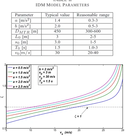
TABLE II
IDM MODELPARAMETERS
Parameter Typical value Reasonable range
a[m/s2] 1.4 0.3-3
b[m/s2] 2.0 0.5-3
DM T R[m] 450 300-600
L0[m] 3 2-5
s0[m] 3.0 1-5
T0 [s] 1.5 1.0-3
v0[m/s] 30 20-40
5 10 15 20 25 29
0.5 1 1.5 2
v
e (m/s)
ζ
a = 0.5 m/s2 a = 1.0 m/s2 a = 1.5 m/s2 a = 2.0 m/s2
a = 2.5 m/s2
b = 2 m/s2 s
0 = 3 m
v
0 = 30 m/s
T
0 = 1.5 s
[image:11.595.66.284.113.351.2]ζ = 1
Fig. 10. ζvs.ve(L0 = 3m,b= 2m/s2,T0 = 1.5s,S0 = 3m,v0 =
30m/s).
implemented by using the TraCI package from the OMNET++ program.
In our experiments, we choose realistic IDM parameters, which are summarized in Table II, including typical settings and reasonable parameter ranges. On the other hand, default parameters are used in OMNET++. Additionally, traffic infor-mation of all vehicles will be updated 10 times per second.
B. Intra-Platoon Dynamics and Parameters
As we have mentioned in section IV, the damping ratio ζ
plays an important role in deciding the characteristic of vehicle dynamics in the transient stage. Fig. 10 illustratesζ versusve
with various a, from 0.5m/s2 to 2.5m/s2. In this figure we
can see that ζ monotonically increases with the increase of
ve. Moreover, a higher a can increase the whole value of ζ
and decrease critical velocity vc accordingly. As depicted in
Fig. 10, vc is approximate 19.3m/sat a = 0.5m/s2 and it
becomes10.3m/sata= 2.5m/s2. These results indicate that
the overdamped region [vc, v0]is enlarged with a largera.
Next, Fig. 11 compares the platoon dynamics in three
typi-cal disturbance cases wheren= 10. In case (a),a= 1.4m/s2,
the corresponding critical velocityvc≈15m/s,vstb = 25m/s
withζ|vstb = 1.34, and vlow= 15m/swithζ|vlow = 1.01; in
case (b), a = 1.4m/s2, v
c ≈ 15m/s, vstb = 25m/s with
ζ|vstb = 1.34, and vlow = 5m/s with ζ|vlow = 0.77; in
case (c), a = 0.7m/s2,v
c ≈ 17.9m/s, vstb = 15m/s with
ζ|vstb = 0.93, and vlow = 5m/s. All other IDM parameters
are typical values selected from table II. For each case, we present three profiles: vehicle velocity, intra-platoon spacing, and platoon length.
In Fig. 11 we can observe that, in case (a), there is no overshoot for the three profiles near the equilibrium points (i.e., ve =vstb andve=vlow), which is in accordance with
200 300 400 500
0 100 200 300 400
Time (s)
l1,8
(m)
200 300 400 500
0 100 200 300 400
Time (s)
l8,15
(m)
200 300 400 500
0 100 200 300 400
Time (s)
l1,8
(m)
200 300 400 500
0 100 200 300 400
Time (s)
l8,15
(m)
200 300 400 500
0 100 200 300 400
Time (s)
l1,14
(m)
200 300 400 500
0 100 200 300 400
Time (s)
l14,27
(m)
(b)
(a) (c)
Fig. 12. Verification of VANET connectivity within a DA-Platoon in three cases
our theoretical analysis. In case (b), there is overshoot but with
no oscillation for velocity profile near the equilibrium ve =
vstb. Moreover, magnitude of gap deviation yj(t) decreases
with the increase of j. Experiment results also show that, if
the platoon size increases enough, the overshoot of platoon
length will converge to 0, which means that the maximum
platoon length is determined by the equilibrium intra-platoon
spacing at vstb. In case (c), intra-platoon spacing oscillates
around the equilibrium points ve = vstb and ve = vlow. In
addition, intra-platoon spacing deviation increases withj and
thus the overshoot of platoon length increases accordingly. Based on the experimental results, we can also estimate the corresponding DA-Platoon parameters. For both case (a) and
(b), the equilibrium intra-platoon spacingSj ≈56.3mand the
maximum platoon size n= 15, where vehicleC8 acts as the
only relay vehicle. While for case (c), the equilibrium
intra-platoon spacingSj≈26.3m, and the maximum platoon size
n= 27, where vehicle C14 acts as the relay vehicle. Fig. 11
illustrates the distances l1,r (between leader and relay) and
lr,n (between relay and tail) in three cases, respectively. We
can observe all the distances are less than DM T R = 450m,
which can maintain VANET topology during disturbance. Moreover, we can calculate the range of the desired inter-platoon spacing based on Eq. (33) and Eq. (32). In both case
(a) and (b), for example, if we choosed0approximately equal
to one intra-platoon spacing, i.e., d0= 60m,θ1 =−0.2, the
minimum velocity in disturbance vlow = 5m/s, then 60 ≤
Ddes
≤80m. To mitigate the impact of underdamped
intra-platoon spacing at vlow, we can choose the maximal value
of Ddes, i.e., Ddes = 80m. In such a case, we can further
estimate the traffic capacity, which is about 1410 vehicles per hour. Similarly, the traffic capacity is estimated to reach up to 1590 vehicles per hour for case (c).
C. Performance of the Driving Strategies
In this subsection, we illustrate the performance of the proposed driving strategies for three consecutive platoons. We choose case (b) in the previous subsection as the disturbance scenario, which represents a typical disturbance scenario in
practice. In each platoon, we letn= 15and we apply typical
IDM parameters in Table II.
First, we verify the proposed driving strategy for leaders.
Assuming that the first leader Ci
1 experiences traffic
150 200 250 300 350 400 450 0 5 10 15 20 25 30 Time (s) Velocity (m/s)
150 200 250 300 350 400
25 30 35 40 45 50 55 60 Time (s)
Intra−platoon spacing (m)
150 200 250 300 350 400 450
250 300 350 400 450 500 550 Time (s)
Platoon length (m)
150 200 250 300 350 400 450
0 10 20 30 40 50 60 70 Time (s)
Intra−platoon spacing (m)
150 200 250 300 350 400 450
100 200 300 400 500 600 Time (s)
Platoon length (m)
150 200 250 300 350 400 450
0 5 10 15 20 25 30 Time (s) Velocity (m/s)
150 200 250 300 350 400 450
0 5 10 15 20 25 30 Time (s) Velocity (m/s)
150 200 250 300 350 400 450
0 10 20 30 40 50 60 Time (s)
Intra−platoon spacing (m)
150 200 250 300 350 400 450
100 150 200 250 300 350 400 Time (s)
Platoon length (m)
[image:12.595.53.517.104.378.2](a) (b) (c)
Fig. 11. Platoon dynamics in three typical disturbance cases with 10 vehicles in a platoon. For velocity vs. time, the 10 curves representv1, v2,· · ·, v10,
from left to right. For intra-platoon spacing vs. time, the 9 curves representS2, S3,· · ·, S10, from left to right.
300 400 500 600
0 5 10 15 20 25 30 Time (s) Velocity (m/s)
300 400 500 600
0 5 10 15 20 25 30 Time (s) Velocity (m/s)
300 400 500 600
−3 −2 −1 0 1 2 Time (s) Acceleration (m/s 2)
300 400 500 600
−3 −2 −1 0 1 2 Time (s) Acceleration (m/s 2)
300 400 500 600
0 100 200 300 400 500 Time (s) spacing (m)
300 400 500 600
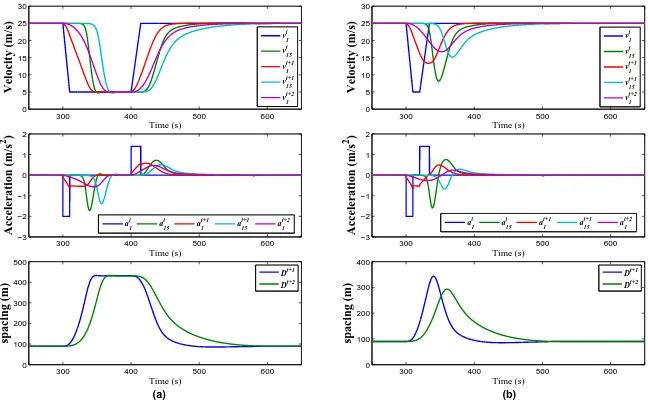
0 100 200 300 400 Time (s) spacing (m) vi 1 vi 15 vi+1 1 vi+1 15 vi+2 1 vi 1 vi 15 vi+1 1 vi+1 15 vi+2 1 Di+1 Di+2 ai 1 a i 15 a i+1 1 a i+1 15 a i+2 1 a i 1 a i 15 a i+1 1 a i+1 15 a i+2 1 Di+1 Di+2 (a) (b)
Fig. 13. Trajectory comparison in difference disturbance scenarios (a) with longer duration:Td= 100s, (b) with shorter duration:Td= 20s.
of the following DA-Platoon leaders in disturbance scenario with different duration Td.
1) disturbance with longer duration Td = 100s: In this
case, all vehicles decelerated to vlow and maintained this
velocity for a certain duration. The simulation results are illustrated in Fig. 13 (a). We can observe a smoother velocity
change and smaller acceleration variation trajectories ofCi+1
1
during the disturbance period compared to that of any
vehi-cle in Pi. Moreover, similar effects also occurred at Ci+2
1 .
Additionally, the maximum inter-platoon spacingDi is about
430m, which is less thanDM T Rand thus can guarantee good
connectivity between two adjacent platoons.
2) disturbance with shorter duration Td = 20s: In this
case, the tail of Pi, Ci
15, did not decelerate to vlow due
to the shorter disturbance duration. We can also see the similar results in Fig. 13 (b) compared to that in Fig. 13 (a). Furthermore, each following DA-Platoon leader experienced a smaller velocity variation compared to its preceding one, which considerably mitigated the original traffic disturbance.
[image:12.595.145.469.418.621.2]1 2 4 6 8 10 12 14 16 18 20 22 24 26 28 30 3233 0
0.5 1 1.5
Sequence of vehicle
Acceleration noise (m/s
2)
Longer duration Td = 100 s Shorter duration Td = 20 s
P i+1
P i
[image:13.595.73.276.273.367.2]P i+2
Fig. 14. Acceleration noise comparison in difference disturbance scenarios
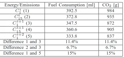
TABLE III
FUEL CONSUMPTION ANDCO2EMISSIONCOMPARISON
Energy/Emissions Fuel Consumption [ml] CO2 [g]
Ci
1 (1) 392.5 984
Ci
15(2) 372.8 935
Ci+1
1 (3) 347.5 872
Ci+1
15 (4) 360.6 905
Ci+2
1 (5) 333.8 837
Difference 1 and 3 11.4% 11.4%
Difference 2 and 3 6.7% 6.7%
Difference 1 and 5 15% 15%
following DA-Platoons, each of which has a smaller average value than its preceding one. This means that the proposed leader driving strategy can effectively improve the traffic flow smoothness. In addition, this improvement becomes more noticeable in sharp disturbance with shorter duration and larger velocity difference ofvstb andvlow, as illustrated in case (b).
To evaluate the proposed strategies’ impact on exhaust emissions and fuel consumption, we apply the emission model in HBEFA (the Handbook of Emission Factors for Road Trans-port) to calculate vehicle emissions and fuel consumption. Specifically, we assume that all vehicles belong to the same emission class “PKWBEuro2 1.4-2L” selected from HBEFA passenger and light delivery vehicle clusters. The experimental disturbance scenario is the same to Fig. 13 (a), while other
parameters are aforementioned. We then estimate the CO2
emissions and fuel consumption during the whole disturbance period, as shown in Table III. We can clearly observe a
consid-erable fuel consumption and emissions reduction among Ci
15
vs.C1i+1,C
i
1vs.C
i+1
1 andC
i
1vs.C
i+2
1 . Note that, if a leader
only applies the constant-spacing strategy, its performance will be the same as that of the tail of the preceding platoon. The results clearly demonstrate the advantages of the proposed driving strategies, in terms of both exhaust emissions and fuel consumption.
VII. CONCLUSIONS
In this paper, we have investigated the dynamics of VANET-enabled platoon under disturbance. In particular, we first proposed a novel disturbance-adaptive platoon (DA-Platoon) architecture, in which both platoon dynamics and VANET behaviors are taken into consideration. With a specific de-sign of the DA-Platoon architecture, we have analyzed the intra-platoon dynamics and we have identified three possible transient responses to different disturbance scenarios. Based
on the analysis, we have further derived the desirable intra-platoon spacing and intra-platoon size, under traffic disturbance and VANET constraints. Next, to mitigate the adverse effects of traffic disturbance, we have also designed a novel driving strategy for the leading vehicle of DA-Platoon, with which we can determine the desired inter-platoon spacing. Finally, extensive simulation experiments have been conducted, which validate our analysis and demonstrate the effectiveness of the proposed driving strategies, in terms of acceleration noise, fuel consumption and exhaust emissions.
REFERENCES
[1] R. Hall and C. Chin, “Vehicle sorting for platoon formation: Impacts on highway entry and throughput,” Transportation Research Part C: Emerging Technologies, vol. 13, no. 5-6, pp. 405–420, Oct. 2005. [2] B. van Arem, C. J. G. van Driel, and R. Visser, “The Impact of
Cooperative Adaptive Cruise Control on Traffic-Flow Characteristics,” Intelligent Transportation Systems, IEEE Transactions on, vol. 7, no. 4, pp. 429–436, Dec. 2006.
[3] R. Rajamani and S. Shladover, “An experimental comparative study of autonomous and co-operative vehicle-follower control systems,” Trans-portation Research Part C: Emerging Technologies, vol. 9, pp. 15–31, 2001.
[4] T. Acarman and U. Ozguner, “Intelligent cruise control stop and go with and without communication,” in American Control Conference, Minneapolis, MN, June, 2006, pp. 4356–4361.
[5] F. Bai and B. Krishnamachari, “Exploiting the wisdom of the crowd: localized, distributed information-centric VANETs [Topics in Automo-tive Networking,” Communications Magazine, IEEE, vol. 48, no. 5, pp. 138–146, May 2010.
[6] T. Taleb, A. Benslimane, and K. Ben Letaief, “Toward an Effective Risk-Conscious and Collaborative Vehicular Collision Avoidance System,” Vehicular Technology, IEEE Transactions on, vol. 59, no. 3, pp. 1474– 1486, Mar. 2010.
[7] P. Kavathekar, “Vehicle Platooning: A Brief Survey And Categorization,” in MESA11, part of the 2011 ASME DETC/CIE., Washington, DC, USA, 2011, pp. 1–17.
[8] S. Yousefi, E. Altman, and R. El-Azouzi, “Study of connectivity in vehicular ad hoc networks,” in WiOpt 2007. 5th International Symposium on, Limassol, Cyprus, Apr. 2007, pp. 1–6.
[9] R. S. Schwartz, R. R. R. Barbosa, N. Meratnia, G. Heijenk, and H. Scholten, “A directional data dissemination protocol for vehicular environments,” Computer Communications, vol. 34, no. 17, pp. 2057– 2071, Nov. 2011.
[10] V. Sadatpour, M. Fathy, S. Yousefi, A. Rahmani, E. Cho, and M. Choi, “Scheduling Algorithm for Beacon Safety Message Dissemination in Vehicular Ad-Hoc Networks,” Communication and Networking, vol. 56, pp. 133–140, 2009.
[11] a. Chen, B. Khorashadi, D. Ghosal, and M. Zhang, “Smoothing Ve-hicular Traffic Flow Using VeVe-hicular-Based Ad Hoc Networking & Computing Grid (VGrid),” in Proc. IEEE ITSC, Toronto, CA, 2006, pp. 349–354.
[12] A. Uchikawa, R. Hatori, T. Kuroki, and H. Shigeno, “Filter Multicast: A Dynamic Platooning Management Method,” in Consumer Communica-tions and Networking Conference (CCNC), Las Vegas, USA, Jan. 2010, pp. 1–5.
[13] Y. Jiang, S. Li, and D. E. Shamo, “A platoon-based traffic signal timing algorithm for major?minor intersection types,” Transportation Research Part B: Methodological, vol. 40, no. 7, pp. 543?–562, Aug. 2006. [14] Y. Zhang and G. Cao, “V-PADA: Vehicle-platoon-aware data access in
VANETs,” Vehicular Technology, IEEE Transactions on, vol. 60, no. 5, pp. 2326–2339, Jun. 2011.
[15] R. Pueboobpaphan, “Understanding the Relationship between Driver and Vehicle Characteristics and Platoon and Traffic Flow Stability for Design and Assessment of Cooperative Adaptive Cruise Control,” in Proc. Transportation Research Board 89th Annual Meeting, Washington DC, USA, 2010, pp. 89–97.
[17] A. Tapani, “Vehicle Trajectory Impacts of Adaptive Cruise Control,” Journal of Intelligent Transportation Systems, vol. 16, no. 1, pp. 181– 200, 2012.
[18] R. Rajamani, S. Choi, and J. Hedrick, “Design and experimental imple-mentation of longitudinal control for a platoon of automated vehicles,” Journal of Dynamic Systems, Measurement, and Control, vol. 122, pp. 681–689, Sep. 2000.
[19] P. Seiler, A. Pant, and K. Hedrick, “Disturbance propagation in vehicle strings,” Automatic Control, IEEE Transactions on, vol. 49, pp. 1835– 1841, 2004.
[20] H. Hao, “Stability and robustness of large vehicular platoons with linear and nonlinear decentralized control for two architectures,” Int. J. Robust. Nonlinear Control, 2012.
[21] G. J. L. Naus, R. P. a. Vugts, J. Ploeg, M. R. J. G. van de Molengraft, and M. Steinbuch, “String-Stable CACC Design and Experimental Val-idation: A Frequency-Domain Approach,” Vehicular Technology, IEEE Transactions on, vol. 59, no. 9, pp. 4268–4279, Nov. 2010.
[22] J. Ploeg, B. T. M. Scheepers, E. van Nunen, N. van de Wouw, and H. Nijmeijer, “Design and experimental evaluation of cooperative adaptive cruise control,” in Proc. IEEE ITSC, Washington, DC, USA, Oct. 2011, pp. 260–265.
[23] L. Y. Wang, A. Syed, G. Yin, and A. Pandya, “Coordinated Vehicle Platoon Control : Weighted and Constrained Consensus and Commu-nication Network Topologies,” in Decision and Control (CDC), 2012 IEEE 51st Annual Conference on, Grand Wailea Maui, HI, USA, Dec. 2012, pp. 4057–4062.
[24] A. Levedahl, “Platooning Dynamics and Control on an Intelligent Vehicular Transport System,” CSOIS, Utah State University, pp. 1–7, 2010.
[25] Y. Zhai, L. Li, and G. Widmann, “Design of switching strategy for Adaptive Cruise Control under string stability constraints,” in American Control Conference (ACC), 2011, 2011, pp. 3344–3349.
[26] S. Vodopivec, J. Bester, and A. Kos, “A survey on clustering algorithms for vehicular ad-hoc networks,” in Telecommunications and Signal Pro-cessing (TSP), 2012 35th International Conference on, Czech Republic, 2012, pp. 52 –56.
[27] C. Han and M. Dianati, “Analytical study of the IEEE 802.11 p MAC sublayer in vehicular networks,” Intelligent Transportation Systems, IEEE Transactions on, vol. 13, no. 2, pp. 873–886, 2012.
[28] A. Kesting, M. Treiber, and D. Helbing, “Enhanced intelligent driver model to access the impact of driving strategies on traffic capacity.” Philosophical transactions. Series A, Mathematical, physical, and engi-neering sciences, vol. 368, no. 1928, pp. 4585–605, Oct. 2010. [29] A. Kesting and M. Treiber, “How Reaction Time , Update Time , and
Adaptation Time Influence the Stability of Traffic Flow,” Computer-Aided Civil and Infrastructure Engineering, vol. 23, pp. 125–137, 2008. [30] M. Treiber and A. Hennecke, “Congested traffic states in empirical observations and microscopic simulations,” Physical Review E, vol. 62, pp. 1805–1824, 2000.
[31] SUMO, “http://sumo.sourceforge.net.”
[32] R. Rajamani, “Transitional controller design through r-R˙ diagrams,”
in Vehicle Dynamics and Control. ISBN: 978-0-387-26396, Springer,
2005.
[33] P. Varaiya, “Smart cars on smart roads: problems of control,” Automatic Control, IEEE Transactions on, vol. 38, no. 2, pp. 195–207, 1993. [34] C. Sommer, R. German, and F. Dressler, “Bidirectionally coupled
network and road traffic simulation for improved ivc analysis,” Mobile Computing, IEEE Transactions on, vol. 10, no. 1, pp. 3–15, 2010.
Dongyao Jia received the B.E. degree in automation
from Harbin Engineering University, Harbin, China, in 1998, the M.E. degree in automation from Guang-dong University of Technology, Guangzhou, China, in 2003. He is currently pursuing the Ph.D. degree in computer science at City University of Hong Kong. He worked as a senior engineer in the telecom field in China from 2003 to 2011. He also took part in the establishment of several national standards for home networks. His current research interests include the cyber-physical systems, vehicular ad hoc networks, and home networking techniques.
Dr. Kejie Lu (S’01-M’04-SM’07) received the
B-Sc and MB-Sc degrees in Telecommunications En-gineering from Beijing University of Posts and Telecommunications, Beijing, China, in 1994 and 1997, respectively. He received the PhD degree in Electrical Engineering from the University of Texas at Dallas in 2003. In 2004 and 2005, he was a Postdoctoral Research Associate in the Department of Electrical and Computer Engineering, University of Florida. In July 2005, he joined the Department of Electrical and Computer Engineering, University of Puerto Rico at Mayag¨uez. He is currently an Associate Professor. His research interests include architecture and protocols design for computer and communication networks, performance analysis, network security, and wireless communications.
Dr. Jianping Wang is currently an associate