City, University of London Institutional Repository
Citation:
White, M. ORCID: 0000-0002-7744-1993 and Sayma, A. I. (2015). System and
component modelling and optimisation for an efficient 10 kWe low-temperature organic
Rankine cycle utilising a radial inflow expander. Proceedings of the Institution of Mechanical
Engineers, Part A: Journal of Power and Energy, 229(7), pp. 795-809. doi:
10.1177/0957650915574211
This is the accepted version of the paper.
This version of the publication may differ from the final published
version.
Permanent repository link:
http://openaccess.city.ac.uk/13379/
Link to published version:
http://dx.doi.org/10.1177/0957650915574211
Copyright and reuse: City Research Online aims to make research
outputs of City, University of London available to a wider audience.
Copyright and Moral Rights remain with the author(s) and/or copyright
holders. URLs from City Research Online may be freely distributed and
linked to.
For Peer Review
System and component modelling and optimisation for an
efficient 10kWe low
temperature organic Rankine cycle utilising a radial inflow
expander
Journal: Part A: Journal of Power and Energy Manuscript ID: JPE-14-0059.R1
Manuscript Type: Original Article Date Submitted by the Author: n/a
Complete List of Authors: White, Martin; City University London, School of Engineering and Mathematical Sciences
Sayma, Abdulnaser; City University London, School of Engineering and Mathematical Sciences
Keywords: organic Rankine cyles, ORC, radial turbine, small scale expander
Abstract:
For Peer Review
For Peer Review
System and component modelling and optimisation for an efficient 10kW
elow
temperature organic Rankine cycle utilising a radial inflow expander
Martin White1, Abdulnaser Sayma1 1
School of Engineering and Mathematical Sciences, City University London, United Kingdom
Corresponding author:
Martin White, School of Engineering and Mathematical Science, City University London, Northampton Square, London, EC1V 0HB, UK
Email: [email protected]
Abstract
Small scale (10kWe) organic Rankine cycles for low temperature applications such as heat recovery and
solar power present a significant development opportunity but limited prototypes have been
developed. This paper aims to address this by describing a system modelling tool which is used to select
a working fluid, optimise cycle conditions, and preliminarily size a radial inflow rotor for an experimental
test rig. The program is a steady-state sizing and optimisation tool which advances on current models by
combining component models and cycle analysis with multi-objective optimisation and turbomachinery
design aspects. Sizing and off-design pump and expander models are based on non-dimensional
characteristic plots, whilst an additional design program achieves an expander rotor design. A novel
objective function couples component and system performance with complexity. Results from an
optimisation study indicate that R1234ze is the optimal working fluid for the defined objective function
with a predicted net power output of 7.32kWe, correlating to a cycle efficiency of 7.26%, and
evaporator and condenser areas of 1.59m2 and 2.40m2 respectively. However, after considering operating pressures and fluid availability, R245fa has been highlighted as the most suitable fluid for a
planned experimental radial expander test rig and a preliminary turbine design is proposed.
Keywords
organic Rankine cycles, ORC, radial turbine, small scale expander
For Peer Review
Introduction
Over recent years there has been a significant interest in organic Rankine cycles (ORC) to convert
thermal energy into power. The ORC differs from the Rankine cycle by using an organic fluid instead of
water allowing the conversion of low temperature heat sources such as solar, geothermal and waste
heat into power. Within the cycle the expander is the most critical component, and it is important that it
operates efficiently considering the low Carnot efficiency of the ORC. Either axial or radial
turbo-expanders, or positive-displacement devices such as screw or scroll machines can be employed.
ORMAT, Tri-O-Gen and Turboden have commercialised large scale ORCs employing
turbo-expanders,1-3 whilst BEP and Electratherm produce units between 20 and 50kWe utilising screw expanders.4,5 With the exception of ENEFTECH, the implementation of scroll expanders remains within experimental systems.6 Although bespoke systems are available, the technical challenges such as the development of an efficient expander, reduce the commercial viability of small-scale systems. However,
with careful component selection and design, an efficient and economical system could have
widespread applications.
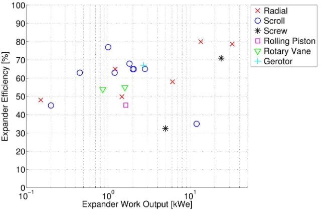
Figure 1 presents current small-scale expander research within the literature. There is limited
interest in screw expanders for powers below 20kWe due to high leakage flows caused by machining
tolerances.7, 8,9 Scroll expanders are low cost, have low rotational speeds, and are common within 1 to 3kWe experimental systems.10-12 However, they remain untested at higher powers, whilst efficiency is limited because the machine is not designed for expansion duties, with values between 60% and 70%
reported within the literature.
[Insert Figure 1. Literature review of current small scale low temperature experimental ORC expanders.]
For Peer Review
Radial turbo-expanders are compact, lightweight and show a high level of technical maturity.
Furthermore, the low enthalpy drop of organic fluids compared to air allowing high pressure ratios to be
efficiently achieved over a single stage. Nguyen et al. and Yamamoto et al. developed experimental
ORCs with radial expanders, achieving 1.47kWe and 0.15kWe with expander efficiencies of 49.8% and
48.0% respectively.13,14 Pei et al. obtained a 1.1kWe power output with an expander isentropic efficiency of 62.5% and further work increased this to 68%.15,16 Kang constructed an experimental rig based on a radial expander, achieving an isentropic efficiency of 78.7% with a 32.7kWe output.17 Inoue et al. developed and tested an ORC turbo-expander. Results indicate a work output of 13.2kWe with an
isentropic efficiency of 80%.18
Referring to Figure 1, efficient expanders within the 10kWe range are found to be sparse. With
the suitability of scroll expanders yet to be proven, and high leakage flows within screw expanders, a
well-designed radial expander is the most suitable choice for the objective power. Despite literature
suggesting performance deteriorates below 50kWe,9, 19 an organic fluid actually facilitates a larger rotor diameter than an equivalent 10kWe expander working with air, potentially reducing rotor losses. At optimal design conditions, a well-designed radial expander could achieve an efficiency of 80%, significantly improving on current scroll and screw expanders. Concerns over higher rotational speeds that require high-speed generators and bearings need to be addressed, although the expected rotational speeds remain significantly lower than those within current turbocharger technology.
Computational modelling plays a large part in ORC research and a number of parametric
thermodynamic and working fluid studies have been undertaken.20-23 Whilst these studies are valuable, it is necessary to include models to predict component behaviour. Furthermore, due to the large
number of interdependencies between cycle parameters an optimisation procedure is essential.24-26 However, without economic modelling a major complexity is the definition of suitable objective
For Peer Review
functions.27 The definition of an objective function, and the choice of component models will also depend upon whether the model is used for system sizing, or cycle optimisation with a known set of
components.
Few researchers have coupled cycle analysis and turbomachinery. Experimental studies make
little reference to expander design, whilst cycle analysis typically assumes constant expander
efficiencies. A complete model should consider expander design and off-design performance within
cycle analysis. Fiaschi et al. developed a 1D design tool, utilising real-fluid properties,19 whilst Lang et al. considers expander design for high temperature ORCs following the design process outlined by
Whitfield & Baines.28,29
Despite the large amount of literature, computational modelling remains the bedrock for ORC
research. However, experimental work remains pivotal to validate models and to understand the
practical issues involved. This project aims to develop a 10kWe radial inflow expander for low
temperature ORCs. This paper outlines the development of a modelling method that combines
thermodynamics, component models and multi-objective optimisation. Optimisation and preliminary
turbomachinery design leads to the selection of a suitable working fluid and rotor design for an
experimental test rig.
System Modelling
The simulation program is a 1D model, developed in FORTRAN, and includes REFPROP for real fluid
properties. With a defined heat source and sink, the program can either size the system or optimise
cycle conditions for a known set of components.
Combining cycle analysis with individual component models allows component behaviour to be
considered within the context of cycle analysis. This modular approach advances on current models
For Peer Review
within the literature that only consider cycle thermodynamics, whilst allowing alternative component
models to be selected for sizing or optimisation. Furthermore alternative models, for example
alternative heat exchanger geometries, can be implemented without too much disruption.
The main variables are the condensation temperature T1, pressure ratio PR, degree of
superheat ΔTSH, and evaporator pinch point PPE. The pinch point is the minimum temperature difference
within the evaporator, and is a trade-off between performance and cost. For system sizing the heat
exchanger geometry is also variable.
The ORC is assumed to be a steady state, subcritical cycle. Although supercritical cycles enable
better matching to the heat source, higher pressures increase system complexity and present more of a
safety concern.20 The working fluid is assumed to be a saturated liquid at pump inlet, although a degree of sub-cooling will be required to prevent cavitation. This assumption is valid since the impact of a small
sub-cooling on the overall cycle will be small. The working fluid is assumed to be a saturated or
superheated vapour at expander inlet as two-phase conditions should be avoided for turbo-expanders.
It is also assumed that no phase change of the heat source or sink occurs as this can significantly impact
the design of the heat exchangers.
Within the cycle analysis, heat losses and pressure drops within the system are also neglected.
However, the pressure drops within evaporator and condenser are estimated to ensure the pressure
drops within these components remain within allowable limits. For the same expander pressure ratio,
system pressure losses will increase the required pump work, although the impact of this is expected to
be small.
For a set of input variables, the fluid properties of the heat source, heat sink and working fluid
at various points within the cycle are calculated. Each component is then simulated sequentially.
For Peer Review
Pump Modelling
The pump increases the working fluid pressure from the condensation pressure P1, to the expander inlet
pressure P2, specified by the pressure ratio. Defining the pump efficiency as the ratio of ideal to real
pump work, the enthalpy h2 at pump exit can be found if the pump efficiency ηP is known (Equation 1).
The enthalpy after an isentropic compression h2s is found as a function of P2 and the entropy at pump inlet s1, since entropy remains constant for an isentropic process (s2s = s1). The pump work per unit mass is the change in enthalpy.
ℎ= ℎ+ℎ− ℎ (1)
The simulation model contains pump models for both sizing and cycle optimisation. The sizing
model assumes a fixed efficiency. Although this assumption is generally acceptable as pump work
remains small compared to expander work, recent work has shown pump work to be more influential
within ORCs than conventional Rankine cycles.30, 31 For cycle optimisation a method developed by Van Putten et al. creates off-design characteristic curves using known operational points for a specified
pump.32 At any operating point, the performance can be described by the non-dimensional head Hnd and non-dimensional volume flow rate Vnd. The relationship between these two parameters can be
expressed as a quadratic equation (Equation 4).
=
(2)
For Peer Review
= (3)
= + + (4)
Where nP and DP are the rotational speed and diameter of the pump respectively, g is the
acceleration due to gravity, V is the volumetric flow rate, and H is the head (Equation 5); ρ1 and ρ2 refer
to the fluid density at the inlet and outlet of the pump respectively.
=1 −
2 + (5)
The pump performance at the design point, and the operating points at which the head and
volumetric flow rates are equal to zero, then provide the quadratic coefficients. For a given pressure
ratio and working fluid flow rate, the pump efficiency ηP is obtained by Equation 6.20 The subscript “d” refers to the design point.
= 1 − 1 −
!
(6)
Evaporator Modelling
For Peer Review
The evaporation process is divided into three stages; single-phase preheating, two-phase evaporation
and single-phase superheating. The working fluid mass flow rate is calculated using the desired
expander inlet conditions, the input heat source, and the evaporator pinch point. The heat exchanger is
then sized to meet this specification. Although the current model assumes a double pipe counter flow
arrangement, a more realistic shell and tube model is currently in development.
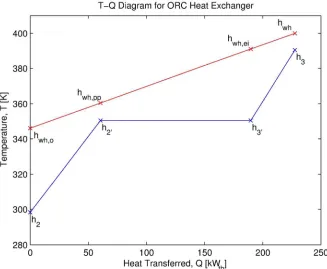
Applying the first law of the thermodynamics, and referring to Figure 2, the evaporator energy
balances are expressed by Equations 7, 8 and 9. These equations express the product of the working
fluid mass flow rate ṁorc and a change in working fluid enthalpy h, to the product of the heat source
mass flow rate ṁwh and a change in the heat source enthalpy hwh. Solving these equations obtains the
working fluid mass flow rate and the heat source temperatures at evaporator exit and the point at
which the working fluid is a saturated vapour.
"#$%ℎ&− ℎ = "'()ℎ'(,− ℎ'(,#+ (7)
"#$%ℎ&− ℎ& = "'()ℎ'(,,-− ℎ'(,+ (8)
"#$%ℎ− ℎ& = "'()ℎ'(− ℎ'(,,-+ (9)
[Insert Figure 2. Schematic of the temperature distribution and heat transfer process between the heat
source (top line) and the working fluid (bottom line) in a typical ORC evaporator.]
To account for variations in fluid properties, each heat transfer stage is discretised into a
number of elements over which a constant change in working fluid enthalpy is assumed. The enthalpy of
For Peer Review
the working fluid at each stage is known and therefore the change in enthalpy within each discrete
element is the total change in enthalpy divided by the number of elements. Starting at a point where
the conditions of both fluids are known, for example at the evaporator exit (h3, hwh) or at the pinch point
(h2’ , hwh,pp), an energy balance obtains the temperature of the heat source. After calculating the
Log-Mean-Temperature-Difference within each element and relating the energy balance to a heat transfer
process (Equation 10), the required heat transfer area Ai is obtained if the overall heat transfer
coefficient Ui is known.
"#$%)ℎ#./,-− ℎ-,-+ = 0-1-234- (10)
The total evaporator area is the summation of each discrete element within each heat transfer
stage.
15= 6 1 (,-7 - 8
+ 6 1 ,9,-7 - 8
6 1 (,-7 - 8
(11)
Ui is calculated by breaking the heat transfer process into three thermal resistances consisting
of two convection terms either side of the wall, and a conduction term through the wall. Ui is therefore
a function of geometry, thermal conductivity of the wall and the local convective heat transfer
coefficients. For the calculation of the local heat transfer coefficients, Gnielinski's correlation for
turbulent flow within tubes is applied for all single-phase flows.33 Chen's correlation for two-phase
For Peer Review
evaporation remains one of the most successful correlations for saturated boiling and is applied to the
working fluid.33
Despite ignoring pressure drops within the cycle analysis, a design check is required to restrict
sizing optimisations from converging to very small pipe diameters which would experience large
pressure drops, significantly increasing working fluid and auxiliary pumping work. For single-phase flow
through a pipe of length L, the pressure drop ΔPL is given by Equation 12; f is the friction factor, Dh is the
hydraulic diameter, ρav is the average density, and u is the flow velocity.
Δ;= < =2 (>
?9@
2 (12)
For two-phase flow, the Müller-Steinhagen and Heck correlation has been proven to provide
suitably accurate results and has been deployed within the simulation program.34
Expander Modelling
Expressing the expander isentropic efficiency as the ratio of real to ideal work, the expander outlet
conditions are determined if the expander efficiency ηe, expander inlet conditions, and outlet pressure
P4 are known (Equation 13). The work output per unit mass is the change in enthalpy. The isentropic
enthalpy at expander outlet h4s is found based on P4 and assuming an isentropic expansion (s4s = s3).
ℎA= ℎ− ,ℎ− ℎA (13)
For Peer Review
Expander Sizing.
For the application and power range considered a radial turbine has beenhighlighted as the most suitable expander. At optimal conditions a radial turbine can achieve efficiencies in excess of 85%, although as the design mass flow rate reduces, the isentropic efficiency will reduce as the size of clearance gaps relative to the rotor size increases. However, a target efficiency of 80% is achievable, surpassing the current efficiencies of screw and scroll expanders within this power range. For this specified efficiency, and defined thermodynamic conditions the non-dimensional specific-speed Ns and specific-diameter Ds may be used to determine the rotational speed
ω and rotor diameter De respectively. Vȩ4 is the volumetric flow rate at the expander outlet and (h3 – h4s) is the isentropic enthalpy drop across the expander.
B= CA
ℎ− ℎA
A (14)
=,ℎ− ℎA A
A (15)
The efficiency of radial inflow expanders have been correlated against B and by Watson & Janota.35 Figure 3 shows that optimal efficiencies above 80% are achieved with Ns ranging between 0.4 and 0.8 and Ds ranging between 3 and 5. The centre point correlates to Ns = 0.6 and Ds = 3.4. Therefore
using these values the required diameter and rotational speed for a given mass flow rate, inlet
conditions, can be obtained by rearranging Equations 14 and 15.
For Peer Review
Using Ns and Ds in this way to size the rotor allows a quick design check to see whether the
required expander is within practical limits, whilst enabling expander design aspects to be considered
within a parametric working fluid selection study. It is important to note these are only characteristic
results and a complete design will require a more detailed analysis. Following a parametric study, a
working fluid with optimal cycle conditions will be obtained, and a 1D through-flow model will result in a
more detailed rotor design. A simple method based on standard radial turbine design theory is outlined
later.
[Insert Figure 3. Digitisation of obtainable efficiency contours for radial inflow turbines correlated
against specific speed and specific diameter by Watson & Janota.35]
Expander Off-Design Performance.
During cycle analysis with an existing expander, it is not suitable to assume that the expander performance remains at the design point. A performance map must be implemented to estimate the expander performance at a particular operating point. In coupling a thermodynamic cycle analysis with an expander performance map the optimal system may not necessarily operate at the expander’s design point. In order words, expander efficiency may be sacrificed for more preferential cycle conditions.Operating at off-design pressure ratios and rotational speeds reduces the isentropic efficiencyof the expander. The main source of this loss is attributed to an incidence loss, causing flow separation and recirculation within the rotor passage. Passage, windage and clearance losses must also be considered, although these effects will vary less significantly with off-design conditions. Although 1D performance models are available for radial turbines these are empirically based using experimental data from air turbines. The validity of these models for organic fluids is unproven,
For Peer Review
requiring either CFD or experimentation to obtain performance maps. Currently a more generic formulation of expander performance is considered just to highlight the intended methodology, which will be replaced in future studies.
Figure 3 has been digitised into a Look-Up Table, which can be accessed within the simulation program. For given expander conditions and rotational speed an estimate of efficiency can be obtained. Although this is useful as a generic characteristic, caution should be taken as the Ns and Ds
values used to obtain Figure 3 refer only to the design point efficiency. Ns is considered a shape factor
with low values indicating a large diameter with small blade heights and therefore small passage areas. Comparatively, a higher value indicates a smaller rotor diameter with a larger flow passage resulting in a higher exit velocity. For the same turbine rotor it is impossible for the rotor geometry to change.
Condenser Modelling
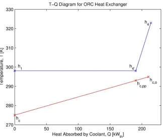
The condenser is divided into two heat transfer regions: single-phase precooling and two-phase
condensation. Applying the first law of thermodynamics, with reference to Figure 4, the energy balances
are expressed by Equations 16 and 17. These equations express the product of the working fluid mass
flow rate and a change in enthalpy, to the product of the heat sink flow rate ṁc and a change in heat
sink enthalpy hc. For a fixed ṁc solving these equations leads to the condenser pinch point and the heat
sink outlet temperature.
"#$%ℎA− ℎA& = "%)ℎ%,#− ℎD,+ (16)
"#$%ℎA&− ℎ = "%)ℎ%,− ℎ%+ (17)
For Peer Review
[Insert Figure 4. Schematic of the temperature distribution and heat transfer process between the heat
sink (bottom line) and the working fluid (top line) in a typical ORC condenser.]
The condenser is modelled with a double pipe counter flow arrangement, and is sized to ensure
that the heat sink and working fluid conditions are met. The same discretisation process, and pressure
drop calculation, outlined for the evaporator is applied. Gnielinski's correlation is used for single-phase
heat transfer whilst Shah's correlation is applied for two-phase condensation.33
Turbomachinery Design Aspects
The results from the cycle analysis will obtain the thermodynamic conditions, the rotor diameter and rotor rotational speed for a given working fluid. However, in order to develop an experimental prototype a 1D through-flow model is required to obtain a more detailed rotor design. Radial expander rotor design is well covered within textbooks 20 so only the key aspects of the model will be outlined here. REFPROP has again been utilised for fluid properties instead of the standard ideal gas laws.19
The rotor design is based on a number of non-dimensional parameters which are set according to values suggested within the literature. To arrive at a preliminary design these parameters are currently fixed, although future work will optimise these parameters to arrive at a more optimal design.
The first two parameters are the isentropic velocity ratio ν and the exit velocity ratio φ3. E is
the ratio of blade tip speed U2 to spouting velocity co, where co is equivalent to the isentropic enthalpy
For Peer Review
drop across the expander. The exit velocity ratio is the ratio of the axial flow velocity at rotor exit cm3
to U2. The subscripts 2 and 3 refer to rotor inlet and outlet respectively.
[Insert Figure 5. Radial turbine rotor geometry viewed from the meridional plane (left), and rotor inlet
(top right) and rotor outlet (bottom right) velocity triangles. C and W correspond to absolute and
relative velocity respectively.]
Rodgers & Geiser correlated expander efficiency against these E and FGand found a peak in efficiency at ν = 0.7 and φ3 = 0.25.
36
For specified thermodynamic conditions co and therefore U2 is
easily found. For a specified blade number, the optimal flow angles at the rotor inlet are then obtained by correlations found in Dixon. 37
The rotor geometry is shown in Figure 5 and is sized based on the rotor radius ratio H =
IJ/IG,LMN, and the exducer radius ratio O = IGP/IGN. These are set to 1.67 and 0.45 respectively according to suggestions within Dixon.37 The stator and rotor loss coefficients account for losses within the stator and rotor passages respectively. Following the suggestions made by Dixon and Whitfield & Baines these have been set to 0.11 and 0.66 respectively. 29,37
With fixed radius ratios and passage loss coefficients, the rotor outlet velocity triangle is fully defined. QG can then be computed using the obtained value of RMG, and the rotor can be sized to pass the required mass flow rate. A parametric investigation of the blade number is undertaken, and the blade number that results in a value of QG closest to 0.25 is selected.
Optimisation
For Peer Review
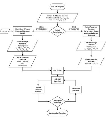
For optimisation with respect to an objective function MINUIT has been implemented within the program. MINUIT is a numerical minimisation program that contains a number of minimisation algorithms. The source files are publically available and can be directly coupled to the ORC program. The developed optimisation program continues the theme of modularity, allowing either system sizing or cycle optimisation. The optimisation strategy is shown in Figure 6, and the differences such as the number of variables, the component models selected and the defined objective functions are highlighted.
System sizing is considered when designing a system for a particular application. This allows the thermodynamic cycle to be optimised assuming that each component performs at its design point. This simplifies the pump and expander models as a desired component efficiency can be specified. These components will then be effectively designed to achieve these efficiencies. However, it also introduces more optimisation variables and requires a more complex objective function. Cycle optimisation requires obtaining the best thermodynamic performance with pre-selected components. This is common within small scale applications where the same set of components may be optimised for different heat sources. Therefore one cannot assume that cycle components are operating at the design point, and off-design performance maps must be included. This is particularly pertinent for the expander where the expander isentropic efficiency will reduce at off-design pressure ratios and rotational speeds.
Within this paper the intention is to size the components for an optimised thermodynamic cycle for a given heat source and sink. Therefore the required optimisation method is for sizing. To demonstrate the cycle analysis optimisation requires a performance map for a suitable ORC radial expander. This is not currently available and therefore a turbine design must first be obtained and tested using either CFD techniques or experimental results. Nonetheless, the cycle optimisation
For Peer Review
methodology is included for the sake of completeness and will be fully implemented when an expander performance map is available.
[Insert Figure 6. The optimisation strategy employed within the ORC program for both sizing and cycle
optimisation.]
Cycle Optimisation
For cycle optimisation, the intention is to achieve the greatest performance for a given heat source, heat
sink and set of pre-selected components. System performance can be measured by cycle efficiency ηorc,
or net power output (We – Wp). It has been widely shown that these parameters do not share an optimal
point because the interaction between the heat source and working fluid is not considered within the
cycle efficiency calculation. An optimal cycle efficiency could well result in a poor utilisation of the heat
source, whilst a lower cycle efficiency could have a better utilisation of the heat source, therefore
producing a higher work output.
For waste heat recovery it is important to achieve the best utilisation of the heat source, and
therefore maximise the work output. However, in an application such as cogeneration where the
remaining heat is utilised, maximising cycle efficiency might be more appropriate.
In either case, with pre-selected components it is assumed that the investment costs have
already been incurred, removing any trade-off between system performance and complexity. This
results in an objective function of minimising the inverse of net power or efficiency with respect to the
condensation temperature, pressure ratio, degree of superheat and the evaporator pinch point.
For Peer Review
min <V =W 1
,− W (18)
Or;
min <V =1
#$%
(19)
V = X4 Y Δ4( ,Z
Sizing Optimisation
For system sizing the objective function must trade-off performance with complexity. Complexity is
closely related to cost, and manifests itself through larger heat exchangers and increasing rotor
rotational speed. Maximising power output will lead to small pinch points and large heat exchangers.
Some researchers consider minimising heat exchanger area per unit power. However, this can lead to
systems with small heat exchangers that do not make full utilisation of the available heat source.26 A method to define a more suitable multi-objective function is now described which aims to:
• Maximise net power output, Wn
• Minimise evaporator area, AE
• Minimise condenser area, AC
• Minimise rotor rotational speed, N
For Peer Review
N e t w o rk E xp a n d e r sp e e d E v a p o ra to r a re a C o n d e n se r a re a 6 1′\ No
rm a li se d Im p o rt a n ce f a ct o r
Net work X 1 1 1 3 4 0.4
Expander speed 0 X 0 0 0 1 0.1
Evaporator area 0 1 X 1 2 3 0.3
Condenser area 0 1 0 X 1 2 0.2
Total 10 1.0
Table 1. Binary matrix for ranking the sizing optimisation objectives.
These objectives are first ranked using a binary matrix (Table 1). At each element within the matrix
the row objective is compared to the column objective. If the row objective is considered more
important than the column objective, that element scores 1, otherwise 0. After completion, the
numbers of 1's in each row are summed up and normalised by adding one. This normalisation ensures
that the lowest ranked objective is still considered even if its tally is zero. The importance factors are
obtained by dividing the normalised values by the sum of all the normalised values.
The multi-objective function can then be expressed as the summation of each objective, multiplied
by its importance factor a (Equation 20). A reference factor scales each objective to the same order of
magnitude. In the absence of scaling, the importance factors become meaningless. It is worth noting
that maximising an objective is the same as minimising the reciprocal of that objective.
For Peer Review
min <V = =WW,$,] > +
15
15,$,] +
1^
1^,$,] + A=
B
B$,]> (20)
Initial results showed significant variation with different evaporator and condenser reference
factors. Low reference values resulted in low output powers suggesting that power is sacrificed for
smaller heat exchangers. An improved objective function aims to:
• Maximise net power output, Wn
• Minimise evaporator area per net power output, AE /Wn
• Minimise condenser area per net power output, AC /Wn
• Minimise rotor rotational speed, N
The resulting multi-objective function is driven by power output within three of the objectives.
Results for this objective function showed much less sensitivity to the reference factors, whilst a
comparison of the percentage breakdown of the objective function to the importance factors further
confirmed its suitability.
min <V = =WW,$,] > +
W,$,]
W
15
15,$,] +
W,$,]
W
1^
1^,$,] + A=
B
B$,]> (21)
Despite this confirmation, the chosen objective function is not ideal as objective ranking and
scaling requires a qualitative understanding of the problem, thereby relying on designer experience. A
more accurate method would quantify system complexity by developing economic models that could
For Peer Review
estimate the cost of each component. An objective function of minimising the system cost per unit
power could then be used which would remove any reliance on designer knowledge.
Results and Working Fluid Selection
Due to the large diversity of ORC applications there is no single optimal working fluid, and fluid
screening remains an important stage for any ORC project. A fluid must have preferential
thermo-physical properties, be chemically stable within the operating range, environmentally friendly,
economically viable, non-corrosive, non-toxic and non-flammable.20, 22, 27, 38 Fluids whose vapour dome has an infinite or positive gradient ensure superheated vapour at rotor exit without requiring a
superheater. Steeper gradients have the advantage of requiring no recuperation.
A review of screening studies resulted in 50 potential fluids. Considering suitable operating
conditions, the evaporation and condensation pressures were calculated. Fluids with sub-atmospheric
condensation pressures or supercritical evaporation pressures were neglected. After removing any
banned fluids, this list reduced to the 18 fluids (Table 2). Common refrigerant mixtures were neglected
as these were found to have high saturation pressures, near critical evaporator pressures or negative
gradient saturated vapour domes.
For the remaining fluids, the sizing optimisation was undertaken with the inputs outlined in
Table 3 and 4. The optimisation results are presented in Table 5.
Of the 18 fluids considered, 3 did not converge. R134a and R152a have negative gradient
vapour domes, which require superheating to ensure a dry expansion. A condensation temperature of
313K would also lead to high condensation pressures of 10.1 and 9.1bar respectively. R1234yf also has a
high condensation pressure of 10.1bar, which after compression would result in operation close to the
critical point.
For Peer Review
Name Value Units
Heat source fluid - Water - Heat source temperature Twh 390 K Heat source pressure Pwh 2.0 bar Heat source flow rate ṁwh 0.75 kg/s
Heat sink fluid - Water - Heat sink temperature Tc 288 K Heat sink pressure Pc 1.01 bar Heat sink flow rate ṁc 1.50 kg/s Pump isentropic efficiency ηP 70 % Expander isentropic efficiency ηE 80 % Evaporator wall thickness the 1.0 mm Condenser wall thickness thc 2.0 mm
Table 3. Fixed inputs for the ORC sizing optimisation study.
For the converged solutions, the optimal condensation temperature ranges from 311.81K for
Isopentane to 316.44K for R227ea. The evaporator and condenser pinch points range from 11.72K for
RC318 to 15.35K for Isopentane, and 11.37K for R124 and 13.79K for R236ea respectively. For all fluids
the optimisation converges to a solution where the superheat is negligible. This confirms the
widespread view that there is no thermodynamic benefit in superheating ORCs.
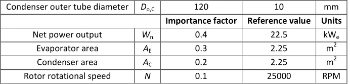
Name Starting value Initial step size Units
Condensation temperature T1 310 10 K
Pressure ratio PR 3.0 0.25 -
Degree of superheat ΔTsh 15 5 K
Evaporator pinch point PPE 15 5 K
Evaporator inner tube diameter Di,E 60 10 mm
Evaporator outer tube diameter Do,E 100 10 mm
Condenser inner tube diameter Di,C 80 10 mm
For Peer Review
Condenser outer tube diameter Do,C 120 10 mm
Importance factor Reference value Units
Net power output Wn 0.4 22.5 kWe
Evaporator area AE 0.3 2.25 m2
Condenser area AC 0.2 2.25 m2
[image:26.612.134.480.133.216.2]Rotor rotational speed N 0.1 25000 RPM
Table 4. Input variables and initialisation values for the ORC sizing optimisation study.
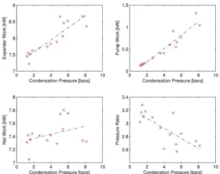
The expander pressure ratio shows the most variation with optimal values ranging from 2.57
for Isobutane to 3.28 for Isopentane. The relationship between pressure ratio and condensation
pressure, pump work and expander work has been investigated in Figure 7. A strong correlation
between increasing condensation pressure and increasing pump and expander work is found. The
enthalpy change for a constant pressure ratio increases with increasing condensation pressure.
Therefore, for the same mass flow rate the required pump work and achievable expander work must
increase. Figure 7(c) shows the net effect of increased pump and expander work. It shows that these
two effects cancel each other out, with only small variations in net power being obtained over the range
of considered working fluids and corresponding condensation temperatures. Figure 7(d) shows the
relation between condensation pressure and pressure ratio. Generally, with increasing condensation
pressure, the optimal pressure ratio reduces.
[Inset Figure 7. Variation in ORC performance with condensation pressure resulting from the sizing
optimisation. (a) expander work (b) pump work (c) net work (d) pressure ratio. ]
Overall these results indicate that regardless of the optimal pressure ratio and condensation
pressure, the optimisation converges to a solution with a similar net power output for all fluids. Coupled
For Peer Review
with the small variations in other thermodynamic variables, it seems the most suitable working fluid is
the fluid that results in the most favourable expander and heat exchanger design.
Figure 8, 9 and 10 display the optimisation results with reference to the objective function
value, the heat exchanger design and expander design respectively.
[Insert Figure 8. Sizing optimisation results for the 15 working fluids considered. (Bars indicate the
objective function value (Equation 21) and the crosses indicate condensation pressure.]
[Insert Figure 9. Evaporator and condenser areas that resulted from the sizing optimisation for the 15
working fluids considered.]
[Insert Figure 10. Expander rotational speed and rotor diameter required for the optimised cycles that
resulted from the sizing optimisation.]
R1234ze achieves the lowest objective function, followed by R142b and Butane, with values of
2.597, 2.692 and 2.737 respectively. From Figure 9 it is apparent that these fluids achieve the smallest
heat exchanger areas, therefore suggesting that the optimisation is driven by the minimisation of heat
exchanger area. There is no significant correlation suggesting that these lower heat exchanger areas are the result of slightly higher pinch points. Furthermore, there is no correlation between changes in the working fluid mass flow rate and the resulting heat exchanger area. This suggests minimising the heat exchanger area is largely dependent upon the predicted pressure loss, with a fluid that has a lower predicted pressure drop permitting a smaller pipe diameter to be used. This is an interesting result highlighting that certain fluids may be a more optimal choice when considering heat exchanger design. This analysis should be extended to consider more complex heat exchanger geometries such as a shell-and-tube arrangement.
For Peer Review
N D2 b2 D3 Ds Dh L Ma2 Ma3
(RPM) (mm) (mm) (mm) (mm) (mm) (mm) (-) (-)
R123 38737 67.04 4.20 40.22 51.87 23.34 21.40 0.91 0.64
R124 60406 40.48 2.58 24.29 31.33 14.10 12.92 0.93 0.61
R141b 45072 66.90 4.20 40.14 51.77 23.29 21.35 0.91 0.64
R142b 71863 39.23 2.63 23.54 30.36 13.66 12.52 0.88 0.59 R227ea 49765 41.30 2.58 24.78 31.96 14.38 13.18 0.97 0.61
R236ea 50322 48.89 3.07 29.33 37.83 17.02 15.60 0.93 0.62
R236fa 52230 45.11 2.86 27.07 34.91 15.71 14.40 0.93 0.61
R245ca 46470 60.55 3.71 36.33 46.85 21.08 19.33 0.93 0.64
R245fa 52230 52.00 3.22 31.20 40.24 18.11 16.60 0.92 0.64
R1234ze 70622 35.45 2.31 21.27 27.43 12.34 11.32 0.92 0.60
BUTANE 95203 39.54 2.68 23.72 30.60 13.77 12.62 0.87 0.59 IBUTAN 100839 36.12 2.45 21.67 27.95 12.58 11.53 0.87 0.58
PENTANE 59050 64.14 4.05 38.48 49.63 22.33 20.47 0.91 0.63
ISOPENTANE 71352 54.95 3.31 32.97 42.52 19.13 17.54 0.94 0.65
RC318 47032 45.82 2.68 27.49 35.45 15.95 14.62 1.01 0.65
Table 6. Resulting expander rotors from the 1D through-flow design program based on the optimised cycle conditions.
Neglecting Isobutane and Butane, expander rotational speeds vary from 40,700rpm for R123 to
75,089rpm for Isopentane, whilst rotor diameter varies from 34.77mm for R1234ze to 65.74mm for
R123. Despite R1234ze and R142b having the lowest objective functions, they result in the highest
rotational speeds. This indicates that during the optimisation, expander rotational speed is sacrificed for
reduced heat exchanger area.
Using the thermodynamic results, the rotor geometry for each was working fluid was obtained using the 1D through-flow expander model (Table 6). Following the assumptions outlined within the turbomachinery design section, the fixed values assumed for E, QG, H and O result in a
For Peer Review
constant specific speed of 0.58 and specific diameter 3.44 for each ORC rotor. This confirms that this set of design parameters is suitable for obtaining a rotor design that lies within the optimal range shown in Figure 3, with the resulting rotor diameters and rotational speeds agreeing with results from the optimisation study. The turbine designs all comprise of 13 blades, with respective absolute and relative flow angles of 73.7° and -32.6° at rotor inlet, and 9.24° and -64.3° at rotor outlet. The low
absolute flow angle at rotor outlet will ensure minimal exit swirl. The degree of reaction is 0.55, which alongside _N and `N lies within the optimal ranges suggested within the literature. This suggests that a good turbine efficiency can be expected. The working fluid Mach numbers Ma have been included in Table 6. Due to the low speed of sound of organic fluids, some Mach numbers at rotor inlet are found to
be transonic. This could introduce uncertainties within the rotor design, and may also mean a
supersonic stator is required.
With the obtained thermodynamic and geometric results from Table 5 and 6 respectively, a
more detailed rotor design phase will be completed, followed by CFD analysis. Varying the
turbomachinery design inputs that are currently fixed, may result in preferential design, but nonetheless
these preliminary designs are expected to offer a good starting point.
Despite the higher rotational speed, the optimisation results for the defined objective function
indicate that R1234ze would be the most suitable working fluid for the defined heat source and sink.
However, it also has the highest condensation pressure of 8.13bar, resulting in an expander inlet
pressure of 21.64bar. This creates more stringent design constraints, which may increase system
complexity and cost. Comparatively R142b has the second lowest objective function with condensation
and evaporation pressures of 5.38bar and 14.47bar respectively. However R142b is a HCFC and is to be
phased out as a result of the Kyoto protocol. The main conclusion from this optimisation study is that
the working fluid selection is not as clear-cut as selecting the fluid with the lowest objective function.
For Peer Review
Even with a complex objective function additional factors such as operating pressures, environmental
properties or availability impact the decision.
Considering the experimental test rig, the fluid should have a reasonably low condensation
pressure to reduce complexity, whilst being readily available. Of the 6 working fluids with a
condensation pressure below 3bar, R245fa and Pentane have the lowest objective function values.
Both fluids sit within a group of fluids with similar heat exchanger configurations, with total
evaporator and condenser areas of 1.75m2 and 3.77m2 for Pentane, and 1.95m2 and 3.90m2 for R245fa respectively. The R245fa expander has a lower rotational speed and rotor diameter of 52,230rpm and
52.00mm respectively, compared to 59,050rpm and 64.14mm for Pentane. Based on this R245fa seems
the most suitable considering that one objective was the reduction of rotor rotational speed, and that
the R245fa rotor has a smaller diameter therefore requiring less material.
R245fa is available within the market, has widely been acknowledged as a suitable low
temperature ORC working fluid, and has previously been employed in a number of experimental ORC
studies. This study therefore further validates the suitability of R245fa for these applications. More
novel working fluids such as the next generation HFOs like R1234ze may prove a more effective solution,
and these should be considered within future studies.
Conclusion
Small scale ORCs have yet to reach maturity for commercial application because of the lack of a suitable
expander. Whilst there have been continual developments at powers below 5kWe, this study has
highlighted a gap within the 10kWe range where there have been limited experimental studies. At this
power range, a radial expander is the most suitable choice and a system simulation program has been
developed to size components and optimise cycle conditions for a radial expander based ORC.
For Peer Review
The results indicated that R1234ze is the optimal working fluid with reference to the novel
objective function. However, this study has also highlighted the difficulty in defining a suitable
optimisation objective function when economics are not considered. Even after running an optimisation
procedure the selection of a suitable working fluid requires a consideration of qualitative factors, and
often relies upon the experience and opinions of the ORC designer.
After consideration, R245fa has been selected as a suitable working fluid for an experimental
test rig. A preliminary rotor design has been achieved which will be further developed, validated using
CFD and constructed into a working experimental prototype before being tested and characterised. The
performance map will then be available for further optimisation studies.
Funding
The authors would like to thank the UK Engineering and Physical Sciences Research Council (EPSRC) for
funding this research.
References
1. ORMAT. ORMAT Technologies Inc. http://www.ormat.com/ (2014, accessed on 17 February
2014).
2. Triogen. Triogen - Power from Heat. http://www.triogen.nl/ (2014, accessed on 17 February
2014).
3. Turboden. Turboden - Organic Rankine Cycle Turbogenerators.
http://www.turboden.eu/en/home/index.php (2014, accessed on 17 February 2014).
For Peer Review
4. BEP. E-Rational - Green electricity out of low temperature waste heat.
http://www.e-rational.net/ (2014, accessed on 17 February 2014).
5. ElectraTherm. ElectraTherm - Energy Efficient Green Machine Heat to Power
http://electratherm.com/ (2014, accessed on 17 February 2014).
6. ENEFTECH. ENEFTECH. http://www.eneftech.com/ (2014, accessed on 17 February 2014).
7. Leibowitz H, Smith IK, Stosic N. Cost Effective Small Scale ORC Systems for Power Recovery
From Low Grade Heat Sources. In: ASME International Mechanical Congress and Expostion,
Chicago, Illinois, USA, November 5-10 2006, paper no. IMECE2006-14284, pp.1-7.
8. Wang W, Wu Y, Ma C, et al. Preliminary experimental study of single screw expander
prototype. Applied Thermal Engineering. 2011; 31: 3684-8.
9. Qiu G, Liu H, Riffat S. Expanders for micro-CHP systems with organic Rankine cycle. Applied
Thermal Engineering. 2011; 31: 3301-7.
10. Bracco R, Clemente S, Micheli D, et al. Experimental tests and modelization of a domestic-scale
ORC (Organic Rankine Cycle). Energy. 2013; 58: 107-16.
11. Declaye S, Quoilin S, Guillaume L, et al. Experimental study on an open-drive scroll expander
integrated into an ORC (Organic Rankine Cycle) system with R245fa as working fluid. Energy.
2013; 55: 173-83.
For Peer Review
12. Lemort V, Declaye S, Quoilin S. Experimental characterization of a hermetic scroll expander for
use in a micro-scale Rankine cycle. Proceedings of the Institution of Mechanical Engineers, Part
A: Journal of Power and Energy. 2011; 226: 126-36.
13. Nguyen VM, Doherty PS, Riffat SB. Development of a prototype low-temperature Rankine cycle
electricity generation system. Applied Thermal Engineering. 2001; 21: 169-81.
14. Yamamoto T, Furuhata T, Arai N, et al. Design and testing of the Organic Rankine Cycle. Energy.
2001; 26: 239-51.
15. Pei G, Li J, Li Y, et al. Construction and dynamic test of a small-scale organic rankine cycle.
Energy. 2011; 36: 3215-23.
16. Li J, Pei G, Li Y, et al. Energetic and exergetic investigation of an organic Rankine cycle at
different heat source temperatures. Energy. 2012; 38: 85-95.
17. Kang SH. Design and experimental study of ORC (organic Rankine cycle) and radial turbine using
R245fa working fluid. Energy. 2012; 41: 514-24.
18. Inoue N, Kaneko A, Watanabe H, et al. Development of Electric Power Generation Unit Driven
by Waste Heat (Study on Working Fluids and Expansion Turbines). In: ASME Turbo Expo 2007:
Power for Land, Sea and Air, Montreal, Canada, May 14-17 2007, paper no. GT2007-27749,
pp.1-12.
19. Fiaschi D, Manfrida G, Maraschiello F. Thermo-fluid dynamics preliminary design of
turbo-expanders for ORC cycles. Applied Energy. 2012; 97: 601-8.
For Peer Review
20. Chen H, Goswami DY, Stefanakos EK. A review of thermodynamic cycles and working fluids for
the conversion of low-grade heat. Renewable and Sustainable Energy Reviews. 2010; 14:
3059-67.
21. Hung TC. Waste heat recovery of organic Rankine cycle using dry fluids. Energy Conversion and
Management. 2001; 43: 539-53.
22. Saleh B, Koglbauer G, Wendland M, et al. Working fluids for low-temperature organic Rankine
cycles. Energy. 2007; 32: 1210-21.
23. Tchanche BF, Papadakis G, Lambrinos G, et al. Fluid selection for a low-temperature solar
organic Rankine cycle. Applied Thermal Engineering. 2009; 29: 2468-76.
24. Rashidi MM, Beg OA, Parsa AB, et al. Analysis and optimization of a transcritical power cycle
with regenerator using artificial neural networks and genetic algorithms. Proceedings of the
Institution of Mechanical Engineers, Part A: Journal of Power and Energy. 2011; 225: 701-17.
25. Sun J, Li W. Operation optimization of an organic rankine cycle (ORC) heat recovery power
plant. Applied Thermal Engineering. 2011; 31: 2032-41.
26. Wang ZQ, Zhou NJ, Guo J, et al. Fluid selection and parametric optimization of organic Rankine
cycle using low temperature waste heat. Energy. 2012; 40: 107-15.
27. Quoilin S, Broek MVD, Declaye S, et al. Techno-economic survey of Organic Rankine Cycle (ORC)
systems. Renewable and Sustainable Energy Reviews. 2013; 22: 168-86.
For Peer Review
28. Lang W, Colonna P, Almbauer R. Assessment of Waste Heat Recovery From a Heavy-Duty Truck
Engine by Means of an ORC Turbogenerator. J Eng Gas Turbines Power. 2013; 135: 10.
29. Whitfield A, Baines NC. Design of Radial Turbomachines. University of Michigan: Longman
Scientific & Technical, 1990, p.397.
30. Borsukiewicz-Gozdur A. Pumping work in the organic Rankine cycle. Applied Thermal
Engineering. 2013; 51: 781-6.
31. Li J, Pei G, Li Y, et al. Analysis of a novel gravity driven organic Rankine cycle for small-scale
cogeneration applications. Applied Energy. 2013; 108: 34-44.
32. Van Putten H, Colonna P. Dynamic modeling of steam power cycles: Part II – Simulation of a
small simple Rankine cycle system. Applied Thermal Engineering. 2007; 27: 2566-82.
33. Ghiaasiaan S. Two-Phase Flow, Boiling and Condensation: In Conventional and Miniature
Systems: Cambridge University Press, 2008, p.613.
34. ASHRAE. 2009 ASHRAE Handbook: Fundamentals: American Society of Heating, Refrigerating &
Air Conditioning Engineers Inc., 2009, p.1000.
35. Watson N, Janota M. Turbocharging: The Internal Combustion Engine: Macmillan Publishers
Limited, 1982, p.608.
36. Rodgers C, Geiser R. Performance of a high-efficiency radial/axial turbine. Journal of
Turbomachinery, Trans Am Soc Mech Engrs. 1987; 109.
For Peer Review
37. Dixon SL. Fluid mechanics and thermodynamics of turbomachinery.2010.38. Bao J, Zhao L. A review of working fluid and expander selections for organic Rankine cycle.
Renewable and Sustainable Energy Reviews. 2013; 24: 325-42.
Appendix A
Notation
a Optimisation importance factor A Heat exchanger area, m2
Cm3 Expander axial exit flow velocity, m/s Co Expander spouting velocity, m/s D Diameter, m
Dh Hydraulic diameter, m Ds Specific diameter f Friction factor
g Acceleration due to gravity, kg m/s2 h Enthalpy, J/kg
H Head, m
Hnd Non-dimensional head L Heat exchanger pipe length, m LMTD Log Mean Temperature Difference, K ṁ Mass flow rate, kg/s
Ma Mach Number N Rotational speed, RPM n Rotational speed, RPS Ns Specific speed P Pressure, bar
PP Pinch point temperature difference, K PR Pressure ratio
r2 Rotor inlet radius, m
r3,rms Rotor outlet root mean squared radius, m rh Rotor shroud radius, m
rs Rotor hub radius, m s Entropy, J/kg K T Temperature, K u Fluid velocity, m/s
U Overall heat transfer coefficient, W/m2 K
For Peer Review
U2 Expander blade tip speed, m/sV Volumetric flow rate, m3/s
Vnd Non-dimensional volumetric flow rate Wn Net work output, W
η Efficiency
ν Expander isentropic velocity ratio ρ Density, kg/m3
φ3 Expander exit flow velocity ratio ω Rotational speed, rad/s
ΔPL Heat exchanger pressure drop, Pa ΔTsh Degree of superheat, K
Subscripts
av Average C Condenser c Heat sink fluidc,o Heat sink fluid at condenser outlet c,pp Heat sink fluid at condenser pinch point co Condensation
d Design point E Evaporator e Expander ev Evaporation orc Working fluid p Pump pc Precool ph Preheat ref Reference value sh Superheat
wh Waste heat source fluid
wh,ei Waste heat source at start of evaporation wh,o Waste heat source at evaporator outlet wh,pp Waste heat source at evaporator pinch point 1 Pump inlet
2 Pump outlet / evaporator inlet
2’ Working fluid in evaporator (saturated liquid) 2s Pump outlet after isentropic compression 3 Evaporator outlet / expander inlet
3’ Working fluid in evaporator (saturated vapour) 4 Expander outlet / condenser inlet
4’ Working fluid in condenser (saturated vapour) 4s Expander outlet after isentropic expansion
For Peer Review
For Peer Review
Working fluid Series
A LT O D P G W P T o x ic it y F la m m a b il it y M o le cu la r m a ss (g /m o l) C ri ti ca l te m p e ra tu re ( K C ri ti ca l p re ss u re (b a r) S a tu ra ti o n p re ss u re @ 3 1 3 (b a r) d S /d T f o r P R = 4 G ro u p
R-123 2,2-dichloro-1 , I , I -trifluoroethane Ethane 1.3 0.02 77 B 1 153.0 456.8 36.6 1.5 0.34 HCFC
R-124 2-chloro-1 , I , I ,2-tetrafluoroethane Ethane 5.8 0.022 609 A 1 136.5 395.4 36.2 5.9 0.07 HCFC
R-141b 1,l -dichloro-1 -fluoroethane Ethane 9.3 0.11 725 117.0 477.5 42.1 1.3 0.15 HCFC
R-142b 1 -chloro-I, 1 -difluoroethane Ethane 17.9 0.065 2310 A 2 100.5 410.3 40.6 5.2 -0.05 HCFC
R-134a 1,1,1,2-tetrafluoroethane Ethane 14 0 1430 A 1 102.0 374.2 40.6 10.1 -2.11 HFC
R-152a 1 ,I -difluoroethane Ethane 1.4 0 124 A 2 66.0 386.4 45.2 9.1 -1.74 HFC
R-227ea 1,1,1,2,3,3,3-Heptafluoropropane Propane 34.2 0 3220 170.0 374.9 29.3 7.0 0.06 HFC
R-236ea 1,1,1,2,3,3-Hexafluoropropane Propane 152.0 412.4 35.0 3.4 0.75 HFC
R-236fa 1,1,1,3,3,3-hexafluoropropane Propane 240 0 9810 A 1 152.0 398.1 32.0 4.4 0.54 HFC
R-245ca 1,1,2,2,3-Pentafluoropropane Propane 6.2 0 693 134.1 446.6 39.3 1.7 0.70 HFC
R-245fa 1,1,1,3,3-pentafluoropropane Propane 7.6 0 1030 B 1 134.0 427.2 36.5 2.5 0.56 HFC
R-1234ze 1,3,3,3-tetrafluoropropene Propene 114.0 382.5 36.4 7.6 -0.33 HFO
R-1234yf 2,3,3,3-Tetrafluoropropene Propene 4 114.0 367.9 33.8 10.1 NaN HFO
R-600 Butane Hydrocarbons 0 1 A 3 58.1 425.1 38.0 3.8 1.11 HC
R-600a Isobutane Hydrocarbons 0.41 0 20 A 3 58.1 407.8 36.3 5.3 0.90 HC
R-601 Pentane Hydrocarbons A 3 72.2 469.7 33.7 1.2 1.75 HC
R-601a Isopentane Hydrocarbons 0.018 0 20 A 3 72.2 460.4 33.8 1.5 0.85 HC
[image:39.612.76.694.103.410.2]R-C318 Octafluorocyclobutane Cyclic Organic Compounds 0.01 0 1 A 1 200.0 388.4 27.8 4.9 0.84 PFC
Table 2. Screened working fluids.
For Peer Review
T1 P1 PR P2 ΔTsh PPE PPC ṁ η Wp We D N AE AC Di,h Do,h Di,c Do,c
(K) (bar) (-) (bar) (K) (K) (K) (kg/s) (%) (kW) (kW) (mm) (RPM) (m2) (m2) (mm) (mm) (mm) (mm)
R123 314.12 1.60 3.10 4.94 0.00 13.59 13.05 0.50 7.88 0.17 7.52 65.74 40700 2.22 4.59 28.31 45.55 46.29 71.06
R124 313.29 5.96 2.84 16.94 0.01 12.99 11.37 0.64 7.85 0.77 8.52 39.72 63437 1.97 3.70 25.04 43.05 37.34 63.64
R141b 313.32 1.34 3.17 4.23 0.00 13.58 12.39 0.37 8.15 0.13 7.55 65.59 47369 2.05 3.96 27.45 45.16 43.38 68.18
R142b 314.17 5.38 2.68 14.42 0.01 12.80 12.40 0.45 7.83 0.55 8.06 38.49 75480 1.77 2.83 23.80 41.81 33.64 59.78
R227ea 316.44 7.68 2.73 20.94 0.00 13.83 13.78 0.92 6.84 1.32 8.66 40.51 52275 2.19 3.38 27.18 45.87 38.69 63.85
R236ea 314.97 3.57 2.93 10.45 0.00 13.59 13.65 0.57 7.45 0.41 7.75 47.86 52979 1.96 4.09 25.48 43.26 41.54 66.95
R236fa 315.48 4.69 2.83 13.25 0.01 13.69 13.79 0.64 7.29 0.60 7.89 44.24 54879 1.87 3.61 25.16 42.87 39.53 64.85
R245ca 314.79 1.83 3.18 5.83 0.00 13.07 13.46 0.44 7.70 0.19 7.63 59.20 48664 2.05 4.33 26.41 44.02 44.17 69.02
R245fa 314.86 2.65 3.09 8.18 0.01 13.13 13.48 0.47 7.67 0.29 7.70 50.99 54881 1.95 3.90 25.37 43.18 40.93 67.04
R1234ze 315.34 8.13 2.66 21.64 0.01 13.55 12.78 0.60 7.26 1.04 8.36 34.77 74034 1.59 2.40 23.55 41.18 32.05 57.77
BUTANE 314.90 3.97 2.61 10.38 0.00 12.94 13.38 0.25 7.60 0.41 7.83 38.67 100088 1.51 2.84 22.04 40.11 33.84 60.39
IBUTAN 314.42 5.49 2.57 14.11 0.03 12.12 12.34 0.29 7.64 0.66 8.46 35.41 105982 1.74 3.19 22.49 41.04 33.75 60.71
PENTANE 314.75 1.22 3.02 3.68 0.04 13.53 13.70 0.23 7.62 0.14 7.45 62.82 62139 1.71 3.77 25.20 42.48 42.92 67.34
ISOPENTANE 311.81 1.45 3.28 4.76 2.00 15.35 12.63 0.21 8.30 0.17 7.22 53.81 75089 1.35 4.12 22.83 40.04 41.49 67.11
RC318 314.21 5.07 3.16 16.03 0.01 11.72 13.42 0.83 7.60 0.91 8.65 44.89 49463 2.52 5.17 27.45 45.62 44.78 70.72
R134a * * * * * * * * * * * * * * * * * * *
R152a * * * * * * * * * * * * * * * * * * *
[image:40.612.67.710.114.427.2]R1234yf * * * * * * * * * * * * * * * * * * *
Table 5. ORC sizing optimisation results.
http://mc.manuscriptcentral.com/jopae
For Peer Review
Figure 1. Literature review of current small scale low temperature experimental ORC expanders. 232x138mm (300 x 300 DPI)
For Peer Review
Figure 2. Schematic of the temperature distribution and heat transfer process between the heat source (top line) and the working fluid (bottom line) in a typical ORC evaporator.
111x83mm (300 x 300 DPI) 7
For Peer Review
Figure 3. Digitisation of obtainable efficiency contours for radial inflow turbines correlated against specific
speed and specific diameter by Watson & Janota.35
156x127mm (300 x 300 DPI)
For Peer Review
Figure 4. Schematic of the temperature distribution and heat transfer process between the heat sink (bottom line) and the working fluid (top line) in a typical ORC condenser.
111x83mm (300 x 300 DPI)
For Peer Review
Figure 5. Radial turbine rotor geometry viewed from the meridional plane (left), and rotor inlet (top right) and rotor outlet (bottom right) velocity triangles. C and W correspond to absolute and relative velocity
respectively. 89x39mm (300 x 300 DPI)
For Peer Review
Figure 6. The optimisation strategy employed within the ORC program for both sizing and cycle optimisation. 186x198mm (300 x 300 DPI)