1
Implementation of a PMN-PT Piezocrystal-based Focused Array with Geodesic
1Faceted Structure
2Zhen Qiu1, Yongqiang Qiu2, Christine E. M. Demore2, Sandy Cochran2 3
1 Department of Electronics and Electrical Engineering, University of Strathclyde, Glasgow, UK 4
2School of Engineering, University of Glasgow, Glasgow, UK 5
6 7
Abstract—The higher performance of relaxor-based piezocrystals compared with piezoceramics is now 8
well established, notably including improved gain-bandwidth product, and these materials have been adopted 9
widely for biomedical ultrasound imaging. However, their use in other applications, for example as a source 10
of focused ultrasound for targeted drug delivery, is hindered in several ways. One of the issues, which we 11
consider here, is in shaping the material into the spherical geometries used widely in focused ultrasound. 12
Unlike isotropic unpoled piezoceramics that can be shaped into a monolithic bowl then poled through the 13
thickness, the anisotropic structure of piezocrystals make it impossible to machine the bulk crystalline 14
material into a bowl without sacrificing performance. Instead, we report a novel faceted array, inspired by the 15
geodesic dome structure in architecture, which utilizes flat piezocrystal material and maximizes fill factor. 16
Aided by 3D printing, a prototype with f# 1.2, containing 96 individually addressable elements was 17
manufactured using 1-3 connectivity PMN-PT piezocrystal - epoxy composite. The fabrication process is 18
presented and the array was connected to a 32-channel controller to shape and steer the beam for preliminary 19
performance demonstration. At an operating frequency of 1 MHz, a focusing gain around 30 was achieved 20
and the side lobe intensities were all at levels below -12 dB compared to main beam. We conclude that, by 21
taking advantage of contemporary fabrication techniques and driving instrumentation, the geodesic array 22
configuration is suitable for focused ultrasound devices made with piezocrystal. 23
Keywords—Geodesic array; PMN-PT piezocrystal; focused ultrasound; 3D printing 24
1.Introduction 25
The use of focused ultrasound as a means to deliver energy has been expanding since the 1990s in areas 26
including high intensity focused ultrasound surgery (FUS) [1], ultrasound-mediated targeted drug delivery 27
(UmTDD) [2] and particle trapping and manipulation [3]. The focused ultrasound beam can be achieved 28
geometrically with a curved piezoelectric bowl or acoustic lens or electrically with a multi-element phased 29
array. The combination of both approaches is also common, with many arrays with overall concave geometry 30
for focusing used in research and clinical practice [4-6]. This is because concave arrays can provide higher 31
2
movement in the focal point is necessary, fewer elements and simpler time delays are needed, reducing the 33
complexity of the driving circuitry. 34
Historically, piezoceramics have been the most commonly used materials in ultrasound transducer arrays 35
but, recently, the improved performance offered by relaxor-based piezocrystals in the Pb(Mg1/3Nb2/3)O3 - 36
PbTiO3(PMN-PT) family has been recognized. Piezocrystals are now used widely in biomedical ultrasound 37
imaging and investigation of their possibilities is under way in nondestructive evaluation, particle 38
manipulation and underwater sonar [7-10] based on piezoelectric properties including k33 ≈ 90% and
39
d33> 1500 pC/N [11]. Bulk, monolithic piezocrystal has little advantage over piezoceramic, with the values of
40
kt being similar, but improved performance can be realized in configurations such as the planks used in
41
biomedical imaging arrays and the pillars used in piezocomposites. 42
PMN-PT itself, termed a Generation I material, is susceptible to changes in functional properties at 43
elevated temperature and pressure [12], but Generations II and III, respectively exemplified by ternary PIN-44
PMN-PT and doped ternary Mn:PIN-PMN-PT, are under development to reduce these effects whilst 45
maintaining much of the performance advantage over piezoceramic, e.g. in terms of k33 and d33 that determine
46
piezocomposite performance. Piezocrystal composites thus have potential to improve the effectiveness of 47
focused ultrasound transducers and the work reported here contributes to this by describing the fabrication and 48
testing of a 2D concave phased array made with Generation I piezocrystal. 49
A widely-reported method to fabricate concave transducer arrays is to place individual single-element 50
transducers in a prefabricated frame at predetermined positions [6, 13]. This requires manufacture of each 51
individual array element separately and the presence of the frame can significantly reduce the array fill-factor, 52
i.e. the percentage surface coverage of the active piezoelectric material, and thus the focusing gain and 53
acoustic energy output of the transducer. As an alternative, Raju et al. [14] proposed an array design using a 54
spherically-focused ceramic bowl with printed electrodes defining the elements. However, fabrication of 55
curved sections from piezocrystal boules would be wasteful of material which costs $0.5 - 3 / mm3, and more 56
importantly, performance would be decreased by the lack of alignment between the piezocrystal axes and the 57
surface of the array. Mechanical forming to focus piezocrystal transducers has been achieved successfully 58
using mechanical hard-press [15] and dimpling techniques [16], but reports are limited to single-element 59
transducers. Other possibilities are to thermally form a 1-3 connectivity piezoelectric - polymer composite into 60
3
frequencies of interest here, below 1.0 MHz, and the values of volume fraction, e.g. VF > 50%, used in 62
focused ultrasound applications. 63
In this short communication, a novel array structure is described to utilize 1-3 connectivity piezocrystal - 64
polymer composites in a geometrically focused array transducer. The practical challenges associated with the 65
fabrication of the array structure and electrical interconnects to the elements are addressed. 3D printing is 66
introduced to aid assembly. The performance of the array is demonstrated and its use with a 32-channel 67
modular array controller is described, illustrating both beam shaping and the relocation of the focus required 68
in focused ultrasound applications. 69
2.Geodesic Structure 70
The faceted spherical structure proposed in this work is drawn from the architectural design of geodesic 71
domes. These domes comprise multiple triangles approximately equal in size, with their vertices lying on the 72
surface of a sphere. The planes of the triangles lie physically inside the sphere but the structure approximates a 73
sphere whilst maximizing the coverage of the aperture with the piezoelectric material. 74
A section of an icosahedron dome structure with dome frequency 6V, referring to a structure with six 75
subdivisions of the original triangles in one icosahedron [19], was chosen for the proposed array. In total, the 76
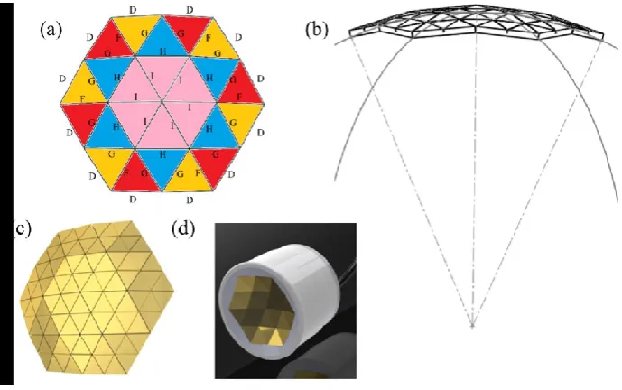
section requires 24 triangular flat plates positioned as shown in Fig. 1. To match a commercial piezoelectric 77
bowl used as a reference, the target operating frequency of the array was 1.0 MHz and its aperture was 62 mm 78
across its largest diagonal, with a natural focal distance of 75 mm, equal to the dome radius, giving f# 1.2. 79
Table 1 lists the four triangular geometries in this design, with their side lengths and corresponding angles. 80
Each triangle is named for its sides taken in a clockwise direction. Five side lengths in total are needed, 81
denoted D, F, G, H and I. Triangles HGG and HII are isosceles and triangles DFG and DGF are scalene; six of 82
each type are required. These triangles were machined by a precision dicing saw (MicroAce 66, Loadpoint 83
Ltd., Wiltshire, UK) with dicing position accuracy of 0.001 mm and theta axis resolution of 0.0005o. 84
To increase the number of array elements for more flexible control over beam forming, each triangular 85
plate was sub-divided into four smaller triangular elements by dicing along the mid-segments of the plates to 86
half their thickness. The number of individual transducer elements was thus increased from 24 to 96, as shown 87
in Fig. 1c, with only one additional step in the fabrication process. Each sub-diced element is connected to an 88
4 90
Figure 1. Illustration of geodesic array transducer. (a) Configuration of 24 triangular plates with four different shapes; 91
(b) overall array configuration with geometrical focus; (c) rear view of the array with 96 sub-diced individual elements; 92
[image:4.595.133.478.27.243.2](d) computer-aided design front view of the array assembly. 93
Table 1. Side lengths and corresponding angles of the four triangular plate designs
Geometries L1 (mm) L2 (mm) L3 (mm)
α1
(Degree)
α2
(Degree)
α3
(Degree)
Triangle-DFG 15.21 14.85 15.44 60.25 61.80 57.95
Triangle-DGF 15.21 15.44 14.85 60.25 57.95 61.80
Triangle-HGG 16.15 15.44 15.44 63.06 58.47 58.47
Triangle-HII 16.15 16.24 16.24 59.64 60.18 60.18
*Li (i = 1, 2, 3)are the side lengths of triangles where i refers to the 1st, 2nd, and 3rd letters respectively of the triangles’
names.
94
3.Piezomaterials 95
The geodesic faceted structure was realized with two different piezoelectric materials: bulk ceramic to test 96
the fabrication process and geodesic geometry and 1-3 connectivity PMN-PT piezocrystal – epoxy composite 97
for performance evaluation. As noted previously, 1-3 composite is necessary to take advantage of the high 98
values of k33 and d33 of PMN-PT.
99
For initial evaluation of fabrication, a pre-electroded piezoceramic plate, thickness 2 mm for 1 MHz 100
operational frequency, (PZ26, Meggitt Sensor Systems, Kvistgaard, Denmark) was diced and separated into 101
24 triangular plates and then sub-diced into 96 sub-elements with 210 μm kerf width and 1 mm depth. 102
Similarly, another set of 24 triangular plates was diced from 1-3 connectivity PMN-29%PT (Sinoceramic Inc., 103
Shanghai, China) - hard polymer (Epofix, Struers A/S, Ballerup, Denmark) piezocomposite fabricated in 104
house using the dice-and-fill method. Epofix was chosen for its low shrinkage, mechanical strength, low 105
Poisson’s ratio, and chemical resistance [20]. The piezocomposite material had a dicing kerf of 113 μm, a
1065
thickness of 1.2 ± 0.02 mm to achieve the 1.0 MHz operational frequency. Electrodes were applied on both 108
sides of the triangular piezocomposite plates using silver ink (118-09A/B, Creative Materials Incorporated, 109
USA) cured at 65°C for 16 h. One electrode face on each triangular piezocomposite plate was part-diced into 110
four smaller triangular divisions, while the ground electrodes on the opposite faces were left intact. 111
4.Array Assembly 112
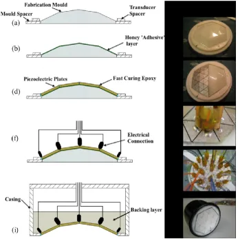
The process to assemble the array transducer from the machined triangular plates is illustrated in Fig. 2, 113
with a corresponding photograph for each step. 114
An important aspect of this process is the placement of each triangular plate in the position needed to 115
create the 3D faceted structure. The target wavelength,
1.5 mm, indicates the need for precision much 116better than 1 mm. Hence, an ABS thermoplastic mould with faceted surfaces matching the geodesic design 117
was made by 3D printing (uPrint SE 3D Printer, Stratasys Ltd, USA), as seen in Fig. 2a and 2c. The layer 118
resolution of the 3D printer was 0.254 mm. Honey thinned in a small container in a warm water bath at 50ºC 119
was used to hold the plates in place, providing lower viscosity compared to other temporary adhesive options 120
such as silicon grease and thus minimizing the layer thickness on the mould (Fig. 2b). The use of honey also 121
allows the mould to be released and the residue to be removed with water. The triangular composite plates 122
were placed on the mould in the arrangement indicated in Fig. 1b and secured with 5 min-curing epoxy 123
(Araldite® Rapid, Huntsman Advanced Materials GmbH, Switzerland), (Fig.2d, e). 124
Because of the thermal sensitivity of PMN-PT piezocrystal, with rhombohedral to tetragonal phase 125
transition temperature, TRT 80ºC [21], conductive silver epoxy (G3349, Agar Scientific, UK) rather than
126
soldering was used for the electric connections. Silver ink was also discarded as an option as its viscosity is 127
much lower than that of silver epoxy and it does not have the physical integrity to maintain its shape during 128
curing. Since this requires ~30 mins curing time at 55ºC, custom-designed interconnect upstands, Fig. 2g, 129
were made to hold the cables in place during curing. These also allowed multiple connections to be made 130
together, increasing the assembly efficiency. Each upstand took the form of a hexahedron comprising two 131
plastic nuts stacked together (528-132, RS Components, Northants, UK). A flexible printed circuit board 132
(fPCB) made in house was attached around the hexahedron and alternate active and ground tracks were 133
connected to micro co-axial cables taken from commercial devices withdrawn from service (Toshiba Medical 134
Systems Europe, Zoetermeer, Netherlands). Each upstand supported six interconnects and the hexahedral 135
6
prepared, it was fixed to the back of the array element assembly with the 5 min-curing epoxy and the signal 137
tracks were connected to the sub-diced triangular composites with conductive silver epoxy (Fig. 2f, g, and h). 138
19 upstands were required for the array: 13 centrally with six micro co-axial cables each, and six at the 139
perimeter of the array with three micro co-axial cables each. The array assembly was then transferred into a 140
pre-heated oven to cure the conductive silver epoxy. 141
Integration with the outer casing followed. A mixture of micro-balloons (K1, 3M, USA) and epoxy 142
(Epofix, Struers A/S, Ballerup, Denmark), mass ratio 1:2, was compressed carefully onto the back of the array 143
element assembly between the interconnect upstands, to act as a mechanical support for the array but with 144
reduced acoustic damping compared with unfilled epoxy because of the higher attenuation and lower acoustic 145
impedance. These parameters cannot be quantified as it is impossible to achieve penetration of sound through 146
the filled epoxy to measure them. After the backing layer was cured, the assembly was released from the 147
mould and the casing was sealed with a watertight rear cover (Fig.2i, j). Finally, remaining honey was 148
removed with warm water and a silver ink common ground was applied on the front face of the array. 149
[image:6.595.127.474.368.715.2]150
Figure 2. Assembly process for faceted bowl arrays: (a) mould with spacers, (b) with honey applied, (c) ready for the 151
piezoelectric plates to be applied; (d) with the plates in place, (e) showing twelve plates, (f) electrical connections 152
added at the plate vertices; (g) detail of the interconnect upstand scheme, (h) shown in overview, (i) with casing, 153
7 5.Array Characterisation and Evaluation
155
5.1. Electrical Impedance Spectroscopy
156
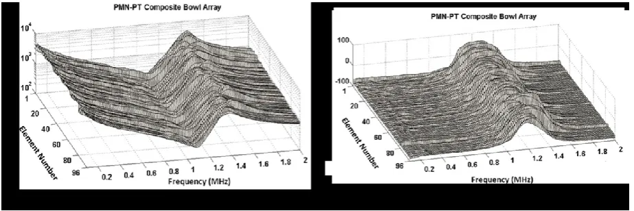
The complex electrical impedance of each of the 96 elements of the piezocrystal composite array was 157
measured with an impedance analyzer (4395A, Agilent Technologies / Keysight, Santa Clara, CA, USA) with 158
the results plotted in Fig. 3. All 96 elements are fully functional without open or short connections. The 159
fundamental resonance and anti-resonance frequencies of the elements across the array, with standard 160
deviation, are fr = 1.05 ± 0.02 MHz and fa = 1.39 ± 0.04 MHz, respectively. The electrical impedance
[image:7.595.68.530.317.471.2]161
magnitude |Z| = 241 ± 57 Ω at the value of frfor each element. The reasons for the large standard deviation are
162
three-fold: non-uniformity of piezocrystal material as purchased from two different production batches 163
(composite velocities measured to be 3285 m/s and 3490 m/s, respectively); variations in the individual 164
piezocrystal composite fabrication; and the systematic size differences between the triangular plates. 165
166
Figure 3. Complex electrical impedance (a) magnitudes and (b) phases of all 96 elements of the piezocrystal composite 167
array 168
5.2. Acoustic Pressure Field Mapping
169
The arrays were connected to commercial array control electronics (FI Toolbox DSL32T, Diagnostic 170
Sonar Ltd, Livingston, UK), customized to provide continuous wave output [22]. To match the 32 171
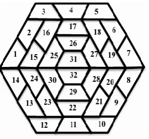
transmission channel count on the driving system, the 96 individual elements of the array were grouped into 172
8 174
Figure 4. Sketch of the distribution of 32 channels on the geodesic array in 2D segmented annular configuration 175
5.2.1 Natural focusing
176
The focusing ability of the geodesic array configuration was tested initially with the bulk ceramic array, 177
with its 32 groups of elements driven at 1.0 MHz, by mapping the beam profile over two perpendicular planes 178
intersecting the transducer focus. To do this, the array was immersed in a tank of degassed water and a 179
0.5 mm diameter needle hydrophone (Precision Acoustics Ltd, Dorchester, UK) was attached to a 3-axis 180
motorized scanning system to measure the acoustic intensity at 0.5 mm increments. A natural focus was 181
achieved with the geodesic structure, as shown in Fig. 5. The -3 dB (full width half maximum, FWHM) beam 182
width at the focus was 2.4 mm and it was 21 mm in length. The intensities of all secondary side lobes were 183
below -12 dB relative to the peak amplitude of the main lobe. 184
185
Figure 5. Normalized output acoustic intensity of the piezoceramic array in its natural focal plane (a) cross section 186
74.5 mm from the centre of the array and (b) axial scan. 187
5.2.2 Electronic focusing and steering
188
The piezocrystal composite array was connected to array control system setup to enable programming of 189
phase delays for steering and focusing. A phase quantisation step of 11.25° was possible, corresponding to a 190
time delay of 31.2 ns at 1.0 MHz (time period 1.0 s). Phase correction of focusing aberrations based on 191
[image:8.595.156.433.432.613.2]9
composite elements compared with the piezoceramic. The focus of the array was found at 69 mm in front of 193
the array and it was then shifted and steered axially and laterally within a volume of 10 × 5 × 5 mm3. 194
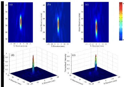
Representative plots of the acoustic intensity fields are shown in Fig. 6. As an example, the -3 dB FWHM 195
beam dimensions at the focus in Fig. 6b were 1.5 mm in width and 15 mm in length. The focusing gain of the 196
array is 30, calculated from the square root of the ratio of the source area to the focal area. Similar to the 197
results from the piezoceramic array, the intensities of the side lobes in the steered beam were below -12 dB 198
compared to the main lobe. 199
[image:9.595.78.512.207.510.2]200
Figure 6. Normalized output acoustic intensity of the piezocrystal array with the focus set electronically to be 201
(a) (0, 0, 64) mm, (b) (0, 0, 69) mm, (c) (0, 0, 74) mm, (d) (0, 0, 74) mm, and (e) (2.5, 0, 74) mm 202
6.Discussion 203
Although the geodesic structure in this communication has been combined with the use of relaxor-based 204
piezocrystals, it can be applied to any material, preferentially those in which natural crystal orientation exists, 205
to form a self-focusing bowl resembling a section of a sphere. Gen. I piezocrystal, PMN-PT, was used here 206
because of its commercial availability, but Gens. II and III piezocrystals will be worth investigating once the 207
materials are available and their behavior is understood [23], not least as the issue of additional DC bias at 208
10
The triangles used to form the proposed geodesic structure are not standard geometries available from 210
piezoelectric material supplies but they can be prepared easily with a dicing saw. Besides the 6V icosahedron 211
dome structure implemented here, other geodesic dome structures exist, e.g. 4V and 5V [19] and could be 212
selected to match the aperture and focal length of a particular array design. 213
3D printing was integrated easily into our assembly process and has shown its potential to aid future 214
ultrasonic transducer development when complex geometrical configurations are needed. The maximum build 215
size of the printer may constrain the array size and aperture but the mould could be printed in several parts for 216
later assembly if a larger scale transducer is needed. 217
Electrical interconnects for multiple elements are a challenge during array assembly, especially with 218
complex shapes such as those discussed here. The interconnection upstands we used worked well with our 219
array and expedited the interconnect process. Although use of flexible PCBs from array to instrumentation 220
might further reduce the effort required for interconnection, this technique still does not offer sufficient length 221
of track and direct cabling is thus preferred. 222
In the preliminary results from electronic focusing and steering, the intensities of the side lobes steering 223
along the axis were as low as -12 dB compared to the main lobe, whilst a -9 dB side lobe was observed when 224
steering the focus off the axis. This increase in sidelobe level is predictable because lateral shifting of the 225
focus was constrained by the 32-channel configuration. Since the electronics are modular, additional channels 226
could be configured to connect all 96 elements of the array individually, improving the focusing quality and 227
steering range. 228
Defocusing and therefore the need for phase aberration correction are unavoidable because of residual 229
aberration from the array itself and from distortion in the medium during ultrasound propagation. Considering 230
only the device, we noted that aberration caused by assembly, associated with the accuracy of the 3D printed 231
mould, was secondary to that caused by non-uniform elements resulting from a combination of the 232
characteristics of the individual piezocrystal composites and the non-uniformity of the piezocrystal material 233
[12]. The hydrophone-based phase correction we adopted gave FWHM beam diameter of approximately one 234
11 7.Conclusions
236
This communication has proposed and evaluated a novel faceted array structure inspired by geodesic dome 237
architecture, allowing the adoption of high performance piezocrystal materials, such as PIN-PMN-PT and Mn-238
doped PIN-PMN-PT piezocrystals, for focused ultrasound applications, since the crystal orientation in 239
crystalline materials prevents formation into a bowl shape in the same way as piezoceramics. The details of 240
assembly of a 96-element array have been described, based on PMN-PT piezocrystal – epoxy composite, with 241
bulk piezoceramic providing a reference device with which good focusing was achieved. Electronic focusing 242
was found to be necessary for the piezocrystal composite array, with satisfactory results achieved even though 243
groups of three elements were connected. The same technique also allows steering of the focus. The array has 244
not been tested at therapeutic levels because the PMN-PT single crystal material available for this work would 245
require an additional DC bias field of about 400V, which was not available for the present work. The 246
customized commercial electronics we used could however further extend the potential of the geodesic array 247
for focused ultrasound applications. 248
Acknowledgements 249
In this work, Dr. Zhen Qiu was supported by the Scottish Universities Physics Alliance. The authors also 250
thank Diagnostic Sonar Ltd for providing the driving system, and Mr. Graeme Casey, University of Glasgow, 251
and Dr. Jack Ng, Heriot-Watt University, for their assistance with this project. 252
References 253
[1] J. E. Kennedy, "High-intensity focused ultrasound in the treatment of solid tumours.," Nature Review Cancer, vol.
254
5, pp. 321-7, 2005.
255
[2] T. M. Allen, "Liposomes. Opportunities in drug delivery," Drugs, vol. 54 Suppl 4, pp. 8-14, 1997.
256
[3] H. M. Hertz, "Standing‐wave acoustic trap for nonintrusive positioning of microparticles," Journal of Applied 257
Physics, vol. 78, pp. 4845-4849, 1995.
258
[4] D. R. Daum and K. Hynynen, "A 256-element ultrasonic phased array system for the treatment of large volumes
259
of deep seated tissue," Ultrasonics, Ferroelectrics and Frequency Control, IEEE Transactions on, vol. 46, pp.
260
1254-1268, 1999.
261
[5] E. S. Ebbini and C. A. Cain, "A spherical-section ultrasound phased array applicator for deep localized
262
hyperthermia," Biomedical Engineering, IEEE Transactions on, vol. 38, pp. 634-643, 1991.
263
[6] V. Auboiroux, E. Dumont, L. Petrusca, M. Viallon, and R. Salomir, "An MR-compliant phased-array HIFU
264
transducer with augmented steering range, dedicated to abdominal thermotherapy," Physics in Medicine and 265
Biology, vol. 56, pp. 3563-82, 2011.
266
[7] Y. Qiu, H. Wang, C. E. Demore, D. A. Hughes, P. Glynne-Jones, S. Gebhardt, et al., "Acoustic devices for
267
particle and cell manipulation and sensing," Sensors (Basel), vol. 14, pp. 14806-38, 2014.
268
[8] P. Sun, G. Wang, D. Wu, B. Zhu, C. Hu, C. Liu, et al., "High Frequency PMN-PT 1-3 Composite Transducer for
269
Ultrasonic Imaging Application," Ferroelectrics, vol. 408, pp. 120-128, 2010.
270
[9] M. F. Wallace, H. Mulvana, P. Marin, K. Mayne, M. P. Walsh, R. Wright, et al., "Parametric Array Design and
271
Characterisation for Underwater Sonar and Medical Strain Imaging Applications," in Ultrasonics Symposium, 272
2007. IEEE, 2007, pp. 305-308.
273
[10] Y. Chen, K.-H. Lam, D. Zhou, Q. Yue, Y. Yu, J. Wu, et al., "High Performance Relaxor-Based Ferroelectric
274
Single Crystals for Ultrasonic Transducer Applications," Sensors, vol. 14, p. 13730, 2014.
12
[11] S. Zhang, S.-M. Lee, D.-H. Kim, H.-Y. Lee, and T. R. Shrout, "Elastic, Piezoelectric, and Dielectric Properties of
276
0.71Pb(Mg1/3Nb2/3)O3–0.29PbTiO3 Crystals Obtained by Solid-State Crystal Growth," Journal of the American 277
Ceramic Society, vol. 91, pp. 683-686, 2008.
278
[12] Z. Qiu, M. R. Sadiq, C. Demore, M. F. Parker, P. Marin, K. Mayne, et al., "Characterization of piezocrystals for
279
practical configurations with temperature- and pressure-dependent electrical impedance spectroscopy,"
280
Ultrasonics, Ferroelectrics and Frequency Control, IEEE Transactions on, vol. 58, pp. 1793-1803, 2011.
281
[13] K. Yohan, A. D. Maxwell, T. L. Hall, X. Zhen, L. Kuang-Wei, and C. A. Cain, "Rapid prototyping fabrication of
282
focused ultrasound transducers," Ultrasonics, Ferroelectrics, and Frequency Control, IEEE Transactions on, vol.
283
61, pp. 1559-1574, 2014.
284
[14] B. I. Raju, C. S. Hall, and R. Seip, "Ultrasound therapy transducers with space-filling non-periodic arrays,"
285
Ultrasonics, Ferroelectrics and Frequency Control, IEEE Transactions on, vol. 58, pp. 944-954, 2011.
286
[15] Q. Zhou, X. Xu, E. J. Gottlieb, L. Sun, J. M. Cannata, H. Ameri, et al., "PMN-PT single crystal, high-frequency
287
ultrasonic needle transducers for pulsed-wave Doppler application," Ultrasonics, Ferroelectrics, and Frequency 288
Control, IEEE Transactions on, vol. 54, pp. 668-675, 2007.
289
[16] K. H. Lam, Y. Chen, K. F. Cheung, and J. Y. Dai, "PMN–PT single crystal focusing transducer fabricated using a
290
mechanical dimpling technique," Ultrasonics, vol. 52, pp. 20-24, 1// 2012.
291
[17] W. A. Smith, "The role of piezocomposites in ultrasonic transducers," in Ultrasonics Symposium, 1989. 292
Proceedings., IEEE 1989, 1989, pp. 755-766 vol.2.
293
[18] G. Harvey, A. Gachagan, J. W. Mackersie, T. McCunnie, and R. Banks, "Flexible ultrasonic transducers
294
incorporating piezoelectric fibres," Ultrasonics, Ferroelectrics, and Frequency Control, IEEE Transactions on, 295
vol. 56, pp. 1999-2009, 2009.
296
[19] B. Carlo, "The Wooden Roofs of Leonardo and New Structural Research," Nexus Network Journal: Architecture 297
and Mathematics, vol. 10, pp. 27-38, 2008.
298
[20] A. L. Bernassau, D. Hutson, C. E. Demore, and S. Cochran, "Characterization of an epoxy filler for
299
piezocomposites compatible with microfabrication processes," IEEE Trans Ultrason Ferroelectr Freq Control, 300
vol. 58, pp. 2743-8, Dec 2011.
301
[21] S. Zhang and T. R. Shrout, "Relaxor-PT single crystals: observations and developments," Ultrasonics, 302
Ferroelectrics and Frequency Control, IEEE Transactions on, vol. 57, pp. 2138-2146, 2010.
303
[22] Z. Qiu, R. Habeshaw, S. Cochran, and L. Dave, "Customized modular multichannel electronics for
ultrasound-304
mediated targeted drug delivery with a geodesic piezocrystal phased array," in Ultrasonics Symposium (IUS), 305
2014 IEEE International, 2014, pp. 811-814.
306
[23] X. Liao, Z. Qiu, T. Jiang, M. Sadiq, Z. Huang, C. Demore, et al., "Functional Piezocrystal Characterisation under
307
Varying Conditions," Materials, vol. 8, p. 5456, 2015.