1
Mechanical testing and modelling of the Universal 2
1implant
23
M.K. Gislason1,2, E. Foster2, D. Main2, G Fusiek2, P Niewczas2, M
Bransby-4
Zachary3, D.H. Nash2
5 6
1. Department of Biomedical Engineering, School of Engineering and 7
Technology, University of Reykjavik, Reykjavik, Iceland 8
2. Faculty of Engineering, University of Strathclyde, Glasgow, UK 9
3. Southern General Hospital, Glasgow, UK 10
11
*Corresponding author. Department of Biomedical Engineering, School of Engineering and 12
Technology, University of Reykjavik, Reykjavik, Iceland, Menntavegur 1, 101 Reykjavik, 13
Iceland 14
15
Tel.: +354 599 6344; fax: +354 599 6201 16
E-mail address: [email protected] 17
18
Abstract 19
20
Understanding the load mechanics of orthopaedic implants is important to be able to predict 21
their behaviour in-vivo. Much research, both mechanical and clinical, has been carried out on 22
hip and knee implants, but less has been written about the mechanics of wrist implants. In this 23
paper, the load mechanics of the Universal 2 wrist implant have been measured using two 24
types of measuring techniques, strain gauges and Fibre Bragg Grating measurements to 25
measure strains. The results were compared to a finite element model of the implant. The 26
results showed that the computational results were in good agreement with the experimental 27
results. Better understanding of the load mechanics of wrist implants, using models and 28
experimental results can catalyse the development of future generation implants. 29
30
2 32
Introduction 33
34
The design of wrist implants has varied greatly in the last decades. The Swanson wrist 35
implant was one of the first implants to gain a commercial success in the US and was based 36
on the concept of a silicone spacer aimed to increase stability in the radiocarpal joint [1]. 37
Fixation was achieved through a proximal radial stem and a distal stem passing through the 38
capitate and into the third metacarpal. With time, a number of fractures on the distal stem 39
were reported [2], leading to a revision of the mechanical design. The next generation implant 40
designs were the Volz [3], and the Meuli [4] implants which demonstrated considerable 41
changes in the overall design compared to the Swanson and used a metal stem made from 42
CoCr and a ball in socket articulations. Other designs followed such as the semi-constrained 43
Trispherical, the Guépar and the biaxial prosthesis which all then were eventually removed 44
from the market [5]. 45
46
In 2005 Shepherd and Johnston [6] evaluated the design criteria for a total wrist prosthesis in 47
terms of loading conditions, contact stresses, wear rate amongst others. The challenges that 48
engineers face in terms of the overall design of a wrist implant are mainly the small area to 49
fixate the implant components to the bone, in particular in the distal attachment, and the 50
variability of the loads and range of motion. In lower limb implants, such as the knee and the 51
hip, the loading conditions are well defined in terms of gait, ascending, descending stairs etc. 52
The load cases on the upper limb are more ambiguous where gripping, lifting and pushing 53
with the wrist in multiple different positions can occur during activities of daily living. It has 54
been shown that during a key turn action in rheumatoid arthritic patients, the average 55
3
Nicol [7], also calculated the joint contact forces on an MCP implant to find that during the 57
same key turn action, the contact force was on average 182.5 N, which represents the load of 58
a single digit, namely the index finger. Kanellopoulos [8] measured external forces on all 59
fingers during gripping with the wrist in various different positions for young healthy 60
subjects of both sexes and reported that the resultant force on the index finger was on average 61
23.1 N. It has also been reported [9] that the load distribution between the fingers was in the 62
ratios 35:30:21:14 between the index, long, ring and little finger respectively. Internal loads 63
acting over all five digits were calculated [9] with the wrist in neutral gripping position, using 64
the biomechanical model presented by Fowler and Nicol [7] to find an average resultant force 65
of 1472 N (standard deviation of 320 N) acting on the MCP joints. Chadwick and Nicol [10] 66
reported overall wrist joint reaction forces exceeding 2000 N, during the horizontal power 67
grip in healthy young subjects. Fok and Chou [11] concluded that the joint reaction forces on 68
the MCP joint could be up to 30 times higher than the external forces applied to the fingers. 69
Although a few studies of the biomechanical modelling of the hand exist, there are large 70
variations in the load application to the hand, but all indicate that during gripping the forces 71
through the wrist can be on the order of 1-2 times bodyweight which is a considerably high 72
load given the small size of the joints in the hand and wrist. 73
74
Given the success of the hip and knee implants over the years, patient expectations have 75
grown, to have a pain free and a stable joint after total joint arthroplasty. The design and 76
manufacturing process of a joint implant is subjected to vigorous standards from regulating 77
authorities [12]. Development of wrist implants is ongoing and since the introduction of the 78
Swanson implant, many designs have been marketed and some with limited success. Third 79
generation implants like the Universal, the ReMotion and the Maestro are now popular in 80
4
proximal and the distal aspect which has been shown by Grosland et al [13] to have an 82
improved property compared to a toroidal shape in terms of stability. All are constructed with 83
a metal stem, a polyethylene spacer and a distal carpal metal plate with screws. Different 84
design aspects can be seen between various implants currently available. This difference can, 85
in particular, be seen between the Universal 2 and the ReMotion on one side and the Maestro 86
on the other. The Universal 2 and the ReMotion have the polyethylene component attached to 87
the distal component in a convex configuration, whereas the Maestro implant has the 88
polyethylene component attached to the proximal stem in a concave configuration, thus 89
resembling more the geometrical features seen in the hip and the knee. 90
91
The finite element method is a powerful tool to calculate in vivo stresses on the structural 92
aspect of the human body and has been used with much success to predict loading behaviour 93
on hip and knee implants [14, 15]. It is widely used during design processes of various 94
components and can be of great importance for orthopaedic implants where experimental 95
work can be difficult to carry out [16]. Little has been written about modelling of the wrist 96
implants. McCullough [17,18] studied the contact area of various wrist implants under 97
simulated muscle loading from the 3 extensor muscles (extensor carpi radialis longus/radialis 98
brevis/ulnaris) and the 2 flexor muscles (flextor carpi radialis/ulnaris) and demonstrated that 99
the Universal 2 implant had greater contact area than the Biax and the Universal total wrist 100
implant as well as lower maximum stress. Bajuri et al [19] published one of the first finite 101
element model of the implanted wrist, focussing on the ReMotion implant. Otherwise little 102
has been published on the mechanical properties of the total wrist implants where many 103
studies have looked at the mechanics of total hip and total knee implants. 104
5
The presented study, demonstrates validation work carried out on the Universal 2 wrist 106
implant and compares with a finite element model created of the implant. Two different types 107
of strain measurements were carried out, firstly using strain gauges and secondly using Fibre 108
Bragg Grating to measure the strain inside the prosthesis. Fibre Bragg grating is an 109
established technique in determining strains in various application, given its light weight, 110
flexibility and resistance to corrosion to name a few [20] and has previously been used to 111
measure the strains in bone tissue [21] and contact pressure in total knee arthroplasty [22]. 112
113
Validation work is difficult to carry out on the wrist joint, as the joint is small and applying 114
measuring devices requires a high degree of joint exposure which will destroy the stabilizing 115
effects of the soft tissue around the joint, thus making it prone to buckling during a uniaxial 116
compression test. In vivo, the load cases on the total wrist implant are more complex than 117
simple uniaxial compression, but by carrying out measurements using a simplified loading 118
scenario and compare to FE model predictions, it will give indications about the mechanical 119
behaviour under more complex load cases. That would be the first step in validating the finite 120
element models. In the presented study, the Universal 2 implant from Integra was used, as it 121
is one of the leading implant used in the UK and the US. 122
123
Methods 124
125
Finite element model 126
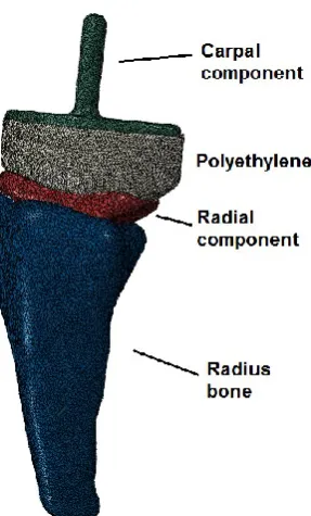
A Universal 2 wrist implant in size large was obtained. It consisted of 3 components: a radial 127
component, a carpal component and a polyethylene component. All three components were 128
scanned using an industrial scanner at the Advanced Forming Research Centre at the 129
6
STL model. The STL geometry was imported into Mimics (Materialise) where the three 131
components manually aligned with each other and virtually inserted into the radius bone. The 132
components were surface meshed using a semi-automated mesher and imported into Abaqus 133
(v.6.11). There the surface meshes were converted into 10 node tetrahedral elements, of type 134
C3D10M. The total number of elements was 246.888 for the full model. The total volume 135
was 10616 mm3, resulting in element density of 23.3 elements/mm3. Interaction between the
136
components was defined either using a surface to surface contact formulation or tie 137
constraints. The connections between the components are listed in Table 1. 138
139
Components Type of contact
Distal part – polyethylene Tie
Polyethylene – radial part Surface to surface contact
Radial part – radius bone Tie
Table 1: Interaction between the components
140
Loading was applied as uniaxial compressive load to the distal component, simulating 141
compressive forces ranging between 0 and 2000 N [10], which can be expected during 142
gripping motion. Figure 1 shows the finite element models. 143
7
Figure 1a – Finite element model of the
[image:7.595.116.239.72.300.2]Universal 2 implant
Figure 1b – Prosthesis inserted into the radius
bone
145
The loading was applied as a pressure over the distal surface of the carpal component. Matlab 146
procedure was written to estimate the surface area by summing up individual areas from each 147
element located at the surface. The overall area was calculated as 349.6 mm2 and a pressure
148
of 5.72 MPa would represent a total load of 2000 N. No slip boundary conditions were 149
applied to the proximal end of the implant. 150
151
The materials were obtained from the manufacturer. The radial component was made from a 152
cast CoCr alloy (ASTM standard F75, ISO standard 5832-4), the carpal plate component was 153
made from titanium alloy (Ti-6AI-4V ELI, ASTM standard F136, ISO 5832-3) and the 154
polyethylene was made from UHMWPe (ASTM Standard 648, ISO Standard 5834-1 +2). 155
The material properties can be seen in Table 1. 156
157
8
[GPa] [MPa] [MPa]
CoCr 207 (220-234) 450 655 8 0.31
Titanium 113.8 970 1450 14 0.30
Cortical bone 20 0.2
Cancellous bone 0.1 0.25
Table 1: Material properties
158
The polyethylene was modelled using the Bergstöm-Boyce model [23] and the material 159
model was obtained from MCalibration (Veryst Engineering) and the model parameters 160
fitted. The reported parameters for the polyethylene model can be seen in Table 2. 161
162 163
μ λ D
24.45 1.486 0.004
Table 2: Polyethylene material coefficients
The finite element model was solved using the implicit solver in Abaqus 164
165
Mechanical testing 166
167
The Universal2 implant was mechanical tested in two different ways. Firstly the external 168
strains on the implant were measured using strain gauges and secondly the internal strain of 169
the implant was measured using a Fiber Bragg Grating sensor. 170
171
9 173
Strain gauges were placed on the radial stem of the implant and the polyethylene component. 174
The polyethylene component and the carpal component were glued together so that no 175
relative motion was allowed between those two components. The implant was placed in 176
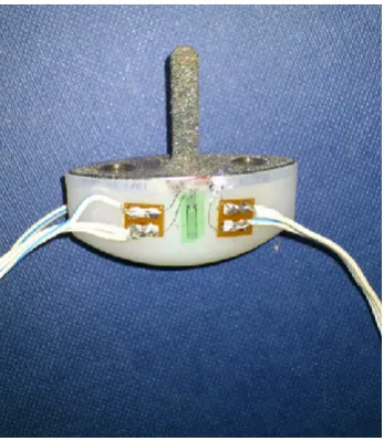
uniaxial compression. The experimental setup and location of strain gauges can be seen in 177
Figures 2a and 2b. 178
[image:9.595.304.478.263.463.2]179
Figure 2a: Experimental setup of the
mechanical testing.
Figure 2b: Strain gauges applied onto the
polyethylene component.
180
Strain data were collected at 100 N intervals with the total force ranging from 0 to 2000 N. 181
182
Fiber Bragg Grating 183
184
The internal strain in the tested implant was additionally monitored using a Fiber Bragg 185
Grating (FBG) sensor. An FBG being a periodic modulation of the refractive index within a 186
section of an optical fibre, when illuminated by a broadband light, reflects a narrow set of 187
[image:9.595.73.268.265.460.2]10
Gaussian, and the wavelength at the maximum reflection is denoted as Bragg wavelength, B.
189
An FBG responds to both strain and temperature, and the resultant Bragg wavelength shift 190
can be described by the following equation: 191
∆𝜆𝐵
𝜆𝐵 = (1 − 𝑝)Δ𝜀 + (𝛼 + 𝜉)Δ𝑇
192
where p is the photo-elastic coefficient, α and ξ are the thermal expansion and thermo-optic 193
coefficients, respectively. For a standard FBG having the Bragg wavelength at 1550 nm the 194
strain and temperature response coefficients are approximately 1.2 pm/µ and 10 pm/°C, 195
respectively. 196
197
A 1 mm diameter hole and 37 mm long was drilled into the proximal aspect of the stem of the 198
radial component using an Electrical Discharge Machining (EDM) where the removal of the 199
metal was carried out by using electrical discharge between an electrode and the implant. 200
This allowed for a long thin hole to be created having minimal effects on the structural 201
integrity of the implant. The optical fibre was placed 37 mm into the stem from the proximal 202
side. The fibre was cleaved so that the grating was located 2 mm away from the end, in order 203
to obtain measurements as close as possible towards the end of the hole. The fibre was fixed 204
using epoxy resin glue. 205
206
The prosthesis was implanted into a saw bone which was done by an orthopaedic surgeon 207
allowing the optic fibre to run through the proximal aspect of the bone. 208
209
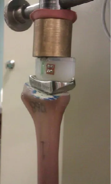
The experimental setup can be seen in Figure 3a and 3b. The implant was tested in a uniaxial 210
compression with load increments of 100 N ranging from 0 to 800 N. 211
11 Figure 3a: Overview of the experimental
[image:11.595.304.484.72.370.2]setup
Figure 3b: Experimental setup
213
Results 214
215
The finite element model was run under the given loading conditions. The stress distribution 216
was analysed and strain results were compared to the findings from the mechanical tests. 217
218
Finite element model 219
220
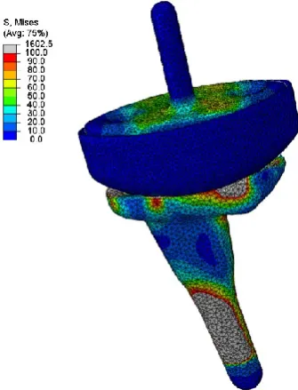
Figures 4a and 4b show the stress distribution on the whole implant under compressive 221
loading of 2000N and the strain distribution on the polyethylene component respectively. 222
12 Figure 4a. Von Mises stress
distribution on the whole implant
under compressive loading of 2000 N
Figure 4b. Strain distribution on the polyethylene
component under compressive loading of 2000 N
224
From Figure 4a and 4b, it can be seen how the load applied on the carpal component is 225
transmitted through the radial component. The strains on the polyethylene component are 226
highest around the surface of the holes in which the carpal component articulates. 227
228
Strain measurements on implant using strain gauges. 229
230
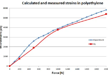
Strain gauge values were read as a function of the applied load on the prosthesis. The load 231
was applied slowly and held for some time at each load interval. The results from the strain 232
gauges were compared with the finite element model. The results from the strain 233
measurements on the polyethylene and the computational predictions can be seen in Figure 5. 234
[image:12.595.269.495.89.293.2]13
Figure 5: Strain as a function of load on the polyethylene component
236
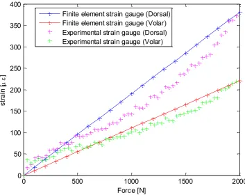
Strain measurements were additionally obtained from the radial stem, with one strain gauge 237
applied towards the distal aspect of both dorsal and volar aspect of the radial component. The 238
14
Figure 6: Strain measurements on the distal aspect of the radial component
240 241
Strain measurements on implant and saw bone using fibre Bragg grating 242
243
A node point was identified on the finite element part of the radial stem, corresponding to the 244
position of the fibre Bragg sensor within the implant. The results of the fibre Bragg grating 245
measurements were compared with the findings of the finite element model as can be seen in 246
Figure 7. 247
248
0 500 1000 1500 2000
0 50 100 150 200 250 300 350 400
Force [N]
st
ra
in
[
]
15
Figure 7: Comparison between Fiber Bragg Grating measurements and finite element model
249 250
Discussion 251
Measuring the load transfer through a wrist implant in vivo is a difficult task. Bergmann et al 252
[24] demonstrated that by placing force transducers inside a prosthesis, it is possible to 253
measure the joint contact forces in larger joints such as the hip and the knee. Such 254
implementation is difficult for the wrist given its small nature. Apart from biomechanical 255
models, few studies have looked at the wrist loading of cadaveric specimens [25.26], but 256
none at the loading of the implanted wrist as it is prone to buckling under uniaxial load in 257
cadaveric specimens. 258
The presented work is the one of the first attempt to create a simplified finite element model 259
16
experimental work was carried out using a simplified uniaxial loading and compared with the 261
findings from a finite element model. In-vivo loading conditions during gripping have been 262
shown [9] to be a combination of proximally, dorsally and ulnarly (radially for the thumb) 263
directed joint contact forces and therefore much more complex than the loads presented in 264
this paper. However the overall magnitude of in-vivo joint contact force acting on the wrist is 265
high and the mechanical trials aimed to simulate extreme loading conditions which are 266
unlikely that patients with total wrist arthroplasty are able to generate. It is however 267
important to understand how the implants behave under a simplified mechanical loading to 268
further understand how they are going to behave under the more complex in-vivo loading and 269
boundary conditions. For the stand alone experiment, the prosthesis was fixed on the 270
proximal aspect of the radial component, whereas for the fibre Bragg experiment the implant 271
was placed into a saw bone to try to mimic in-vivo fixation. From the experimental results it 272
can be seen that the dorsal aspect of the prosthesis experiences higher loading than the volar 273
aspect which partially can be explained by the volar offset of the geometry of the stem. From 274
Figure 6, it can be seen that the results from the finite element model are in good agreement 275
with the volar strain gauge, although the model over predicts the strain on the dorsal side. The 276
measured strain values from the polyethylene component also demonstrated a good 277
agreement with the experimental results. It can be argued that using the Bergström-Boyce 278
material model will give accurate results, when used to model polyethylene orthopaedic 279
materials. 280
From the strain gauge and the fibre Bragg grating measurements on the radial component, it 281
can be seen, by comparing the strain levels in Figure 6 to the ones in Figure 7, that the strain 282
decreases towards the centre of the radial stem. The total load for the implanted prosthesis 283
was 800 N compared to the 2000 N for the stand alone prosthesis, which was due to the 284
17
From the Fibre Bragg data, hysteresis in conjunction with a non-linear strain curve was seen 286
in the experimental results which can be explained by the interaction between the optic fibre, 287
the epoxy resin to which it was attached and the metal implant. However the overall trend is 288
well in agreement with the results of the finite element model. Using the Fibre Bragg method 289
gives experimental results in locations that otherwise would have been impossible to reach 290
using strain gauges and therefore can give more in depth analysis of the three-dimensional 291
strain field within the prosthesis. 292
From table 1, it can be estimated that the proportionality of the strain for the cobalt chrome is 293
around 3100 µε but the maximum strain around the surface was measured and calculated to 294
be around 380 µε under 2000 N compressive load. This demonstrates that the strains on the 295
radial stem are substantially lower than the yield limit and that the stem would be unlikely to 296
fracture in vivo, even though subjected to more complex multi-axial loading scenario. The 297
model does though not take into account poor bone material quality as can be seen in some 298
patients, making proximal and distal fixation a greater challenge. However more research is 299
needed to understand the load mechanics of the prosthesis in-vivo and to quantify the overall 300
loading the whole implant is exposed to during activities of daily living of total wrist implant 301
patients. Future work will incorporate a full three dimensional modelling of the implanted 302
wrist to obtain further information about the load transfer characteristics of the Universal 2 303
wrist implant subjected to multi-axial loading. 304
305
Limitations 306
There are many limitations to the presented study, in particular how the loading is applied as 307
well as other boundary conditions. The modelling and testing does not incorporate the 308
18
bone quality will difficulty in fixation which were not incorporated into the model. The 310
model only looks at the loading in a steady state but doesn’t incorporate any time dependent 311
loading behaviour. A full detailed convergence study was not performed on the number of 312
elements, due to the fact that orphan meshes were used to construct the model and changing 313
the element density would require a new model for each case. However a small comparison 314
between a finer mesh model and a coarser mesh model was made and based on the results it 315
was assumed that the element density presented in the paper was sufficient to obtain accurate 316
results. 317
318
Acknowledgements 319
The authors would like to thank Mr. Juan Fuente Gonzalez and the staff at the University of 320
Strathclyde’s Advanced Forming Research Centre for the help of scanning and creating three 321
19 References
323 324
1. Swanson A. Flexible implant arthroplasty for arthritic disabilities of the radiocarpal 325
joint. A silicone rubber intramedullary stemmed flexible hinge implant for the wrist 326
joint, Orthop Clin North Am., 1973 , 4(2), pp:383-94. 327
2. Jolly SL, Ferlick DC, Clayton ML, Dennis DA, Stringer EA. Swanson silicone 328
arthroplasty of the wrist in rheumatoid arthritis: A long-term follow-up, Journal of 329
Hand Surgery, 1992, 17(1), pp:142-149. 330
3. Volz RG. Clinical experience with a new total wrist prosthesis, Archiv für 331
orthopädische un Unfall Chirurgie, 1976, 85, pp: 205-209. 332
4. Meuli HC, Meuli total wrist arthroplasty, Clinical Orthopaedic Related Research, 333
1984, 187, pp:107-111. 334
5. Sheperd DET and Johnstone AJ. D. A new design concept for wrist arthroplasty, 335
Mechanical Engineering and Physics, 2002, 24, pp: 641-650. 336
6. Sheperd DET and Johnstone AJ. D. Design considerations for a wrist implant, Proc. 337
IMechE Part H, Engineering in Medicine, 2005, 219, pp: 43-52. 338
7. Fowler N and Nicol AC. A biomechanical analysis of the rheumatoid index finger 339
after joint arthroplasty, Clinical Biomechanics, 2002, 17, pp:400-405. 340
8. Kanellopolous A. Three dimensional biomechanics of the hand and wrist in precision 341
grip, 2011, PhD thesis, University of Strathclyde, Glasgow, UK. 342
9. Gislason M, Nash DH, Nicol AC, Kanellopoulos A, Bransby-Zachary M, Hems TEJ, 343
Condon B, Stansfield B. A three dimensional finite element model of maximal grip 344
loading in the human wrist, Proc. IMechE Part H, Engineering in Medicine, 2009, 223 345
20
10.Chadwick EKJ and Nicol AC. Elbow and wrist joint contact forces during 347
occupational pick and places activities. Journal of Biomechanics, 2000, 33, pp:591-348
600. 349
11.Fok KS and Chou SM. Development of a finger biomechanical model and its 350
considerations, Journal of Biomechanics, 2010, 43, pp:701-713. 351
12.Aitchison GA, Hukins DWL, Parry JJ, Shepherd DET, Trotman SG. A review of the 352
design process for implantable orthopaedic medical devices, The Open Biomedical 353
Engineering Journal, 2009, 3, pp:21-27. 354
13.Grosland N, Rogge RD, Adams BD. Influcence of articular geometry on prosthetic 355
wrist stability, Clin Orthop Rel, Res, 2004, No 421, pp: 134-142. 356
14.Knight LA, Pal S, Coleman JC, Bronson F, Haider H, Levine DL, Taylor M, 357
Rullkoetter PJ. Comparison of long-term numerical and experimental total knee 358
replacement wear during simulated gait loading, Journal of Biomechanics, 2007, 40, 359
pp: 1550–1558. 360
15.Martelli S, Taddei F, Cristofolini L, Schileo E, Rushton N, Viceconti M. A new hip 361
epiphyseal prosthesis: Design revision driven by a validated numerical procedure, 362
Medical Engineering and Physics, 2011, 33, pp: 1203-1211. 363
16.Prendergast P. Finite element models in tissue mechanics and orthopaedic implant 364
design, Clinical Biomechanics, 1997, 12(6), pp: 343-366. 365
17.McCullough MBA. Clinical and biomechanical analysis of total wrist arthroplasty 366
devices, 2006, PhD thesis, University of Iowa, Iowa, USA. 367
18.McCullough MB, Adams BD, and Grosland NM. The Effect of Articular Surface 368
Shape and Tendon Forces of Total Wrist Arthroplasty Systems: A Finite Element 369
21
19.Bajuri MN, Kadir MRA, Murali MR, Kamarul T. Biomechanical analysis of the wrist 371
arthroplasty in rheumatoid arthritis: a finite element analysis, Medical and Biological 372
Engineering and Computing, 2013, 51(1), pp:175-186. 373
20.Liu RM, Liang DK., Asundi A. Small diameter fibre Bragg gratings and applications, 374
Measurement, 2013, 46, pp: 3440-3448. 375
21.Fresvig T, Ludvigsen P, Steen H, Reikerås. Fiber optic Bragg grating sensors: An 376
alternative method to strain gauges for measuring deformation in bone, Medical 377
Engineering and Physics, 2008, 30, pp:104-108. 378
22.Mohanty L, Tjin SC, Lie DTT, Panganiban SEC, Chow PKH. Fiber grating sensor for 379
pressure mapping during total knee arthroplasty, Sensors and Actuators A, 2007, 135, 380
pp: 323-328. 381
23.Bergström JS and Boyce MC. Constitutive modelling of the time-dependent and 382
cyclic loading of elastomers and application to soft biological tissues. Mechanics of 383
Materials, 2001, 33, pp: 523–530. 384
24.Bergmann G, Deuretzbacher G, Heller M, Graichen F, Rohlmann A, Strauss J, Duda 385
GN. Hip contact forces and gait patterns from routine activities, Journal of 386
Biomechanics, 2001, 34, pp:859-871. 387
25. Palmer A and Werner FW. Biomechanics of the distal radioulnar joint, Clinical 388
Orthopaedics and Related Research, 1984, 187, pp: 26-35. 389
26.Pfaeffle HJ, Fischer KJ, Manson TT, Tomaino MM, Herndon JH, Woo S. A new 390
methodology to measure load transfer through the forearm using multiple universal 391
force sensors, Journal of Biomechanics, 1999, 32, pp: 1331-1335. 392