Feasibility Study of Complex Sheet Hydroforming Process:
Experimental and Modelling
Mohamed Mohamed
1,a*, David Carty
1,b, John Storr
1,c, Nicola Zuelli
1,d,
Paul Blackwell
1,eand David Savings
2,f1Advanced Forming Research Centre (AFRC), University of Strathclyde, Glasgow, UK
2Rolls-Royce plc, Derby, UK
a*[email protected], b[email protected],
c[email protected],d[email protected], e[email protected] and f[email protected]
Keywords: Inconel 718, Hydroforming, Load Path, Finite Element Method (FEM)
Abstract. The application of finite element method (FEM) in the area of metal forming and material processing has significantly increased in the recent years. The study presented provides details of the development of a finite element modelling approach to form a part via a sheet hydroforming (SHF) process. Both FEM analysis and experimental trials were introduced in this study to produce a complex shaped component from Inconel 718 material. The FEM provides a robust feasibility study for forming this part in terms of blank design, load path and process design optimisation. The simulated hydroformed part was validated by performing experimental trials. The analysis demonstrated close correlation between the predicted FE model and the physical trial.
Introduction
Hydroforming is a widely used industrial process to form complex shaped components. Compared to other traditional manufacturing methods (such as stamping), hydroforming enables the forming of parts with better quality in terms of tighter tolerances, increased rigidity and lower manufacturing costs resulting from a reduced number of forming and assembly operations. Moreover, with the advent of new technological capabilities, in particular more complex and improved control systems, hydroforming has become a flexible, reliable, and hence attractive technology [1].
Hydroforming deep drawing is one of the hydroforming processes used in industry to produce complex sheet components with a high drawing depth. A pressurised fluid acts against a workpiece. As the punch travels, the workpiece begins to deform into the required shape. The main advantages of sheet hydroforming are: improvement of material formability, reduction of the effect of friction on the formed part accuracy and the reduction of forming stages [3].
The analysis of tearing and wrinkling as common failure modes in hydroforming has highlighted that they are caused by inappropriate interaction between the fluid pressure and the punch stroke. Fig. 1 shows schematically the interaction between the pressure and the punch stroke. Failure of the part by wrinkling is a result of insufficient fluid pressure and high punch stroke (green dashed line load path in Fig. 1). Failure by rupture on the top and wall of the part is a result of excessive fluid pressure with insufficient punch stroke (blue dashed line load path in Fig. 1). In this work, a suitable and optimised punch-stroke pressure path (solid red line load path in Fig. 1) is achieved to avoid rupture and wrinkling [4, 5].
Fig.1. Schematic representation of the interaction between the pressure and punch stroke.
Experimental Programme
In all experimental trails, the Inconel 718 sheet material with a thickness of 1.6 mm and chemical composition (50 - 55 % Ni+Co, 17 - 21 % Cr, BAL Fe, 4.75 - 5.5 % Nb+Ta, 2.8 - 3.3 % Mo, 0.65 - 1.15 % Ti and 0.2 - 0.8 % Al) was used.In the numerical calculations of the forming process the material data presented in Table 1 were used. The mechanical properties have been determined experimentally in the tensile test.
Table 1. Material data used in the FEM calculations
Paramter Value
Density[g/cm3] 8.19
Young’s Modulus E [GPa] 200
Yield Stress (0.2 %) Rp0.2 [MPa] 492
Tensile Strength Rm [MPa] 902
Uniform Elongation [%] 43
Normal Plastic Anisotropy Ratio[-] 0.92
Experimental Setup and Process Design.The optimisation of load path and process design was a key part in this study. The purpose of the FE modelling was to design and predict the forming process in terms of the hydroforming stages, pressure cycle and the capability of the FE code to accurately implement the process and the FE predicted load path. The 1000 Tonne hydroforming press used for the validation work operates by using a cam control system. Each of the cams are adjusted in height using a nut which sets a dial-test indicator (DTI) position to adjust the allowable pressure applied to the component at a certain stroke position within the forming cycle.The part was hydroformed to a total height of 90 mm via two separate hydroforming stages (45 mm and 43 mm + 2 mm coining) with an inter-stage heat treatment performed between the two hydroforming stages to recover the material ductility. Fig. 3 shows the hydroforming process design for the part. The coining stage,performed using a coining ring as shown in Fig. 2, was carried out directly after the second hydroforming stage. The coining of 2 mm depth was carried out to achieve a required fillet with radius (5 mm) in the flange of the part.
Stroke
Pres
su
re
Load Path
Tearing
[image:2.595.52.533.370.480.2]0 500 1000 1500 2000 2500 3000 3500 4000
0 10 20 30 40 50
Press
Pressure
P1
(Ps
i)
[image:3.595.108.503.81.304.2]Stroke (mm)
Fig.2. Process design for the part.
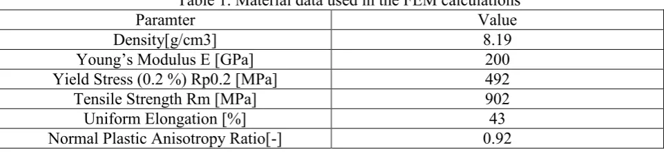
Experimental Trials. In this section, the pressure cycles for each forming stage of the component are presented in terms of relationship between the pressure and stroke. This relationship is known as the “load path” in the hydroforming process. The load path was loaded into the hydraulic press based on the FEM investigation.
Hydroforming Stage 1. Based on the model iterations adopted in the FEM, the load path was optimised to avoid tearing and wrinkling. Fig.3a and 3b show the predicted load path and experimental formed part from the first hydroforming stage with height of 45 mm.
Fig.3. (a) Load path for hydroforming stage 1 and (b) hydroforming stage 1 formed part.
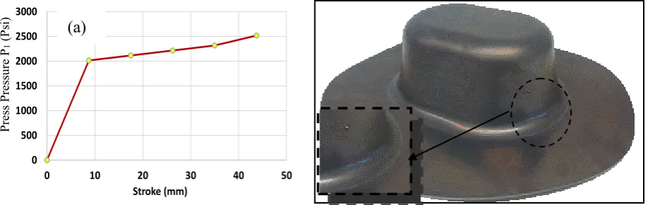
Hydroforming Stage 2. Prior to the second stage, the part formed from the first hydroforming stage went through an inter-stage heat treatment. The second hydroforming stage for the part was performed by applying the predicted load path as outlined in the FEM analysis (Fig.4a), and is shown in Fig.4b. The required height and fillet radius were hydroformed successfully.
SHF1 (45 mm)
Coining (2mm)
SHF2 (43mm) Annealing
[image:3.595.80.486.471.589.2]Fig.4. (a) Load path for hydroforming stage 2 and (b) hydroforming stage 2 formed part.
Process FEM Simulations
[image:4.595.77.536.86.231.2]The baseline model was set up in PAM-STAMP (2G 2015) FE software. Both the tool and the blank were meshed with 4-node shell elements with a mesh refinement of level 3. The boundary conditions were assigned to each part of the tool. In this study, a series of FE simulation models were performed to investigate the modelling approaches with a suitable blank shape, load path and forming process. The optimised blank shape and the FE model for the proposed part are shown in Fig.5a and 5b.
Fig.5. a) Optimised blank shape and b) FEM model for proposed part.
FE Model Validation. This section describes a key part of the project work related to the validation of the FE model using experimental trials for the first and second stages of the hydroforming process of the part. The validation work phases include:
First validation (initial evaluation) of the formed part height and forming quality in relation to tearing and wrinkling. This work was performed after the experimental trials were completed.
Second validation which included a direct comparison of the thickness distribution of the FE simulated part compared to the scan of the formed part from the GOM Atos non-contact measurement system.
R203
D(t)
Coining Ring
Fixed Punch Movable
Die
Applied Pressure (mm)
(b) 0
500 1000 1500 2000 2500 3000
0 10 20 30 40 50
Pr
ess
Pr
essu
re
P1 (
p
si)
Stroke (mm)
(a) (b)
P
re
ss
P
re
ss
ure
P1
(P
si)
[image:4.595.85.527.411.600.2] Final validation which included a direct comparison of the part geometry by electronically overlaying the FE simulated part with the scan of the formed part using the GOM Atos system to check the deformation features of the part.
Model Validation- Hydroforming Stage 1. Fig.6 shows the initial FE model validation where a direct comparison of the simulated and formed parts was performed using different views. A close correlation between the model and trial output in terms of part deformation was observed. This initial FE model validation provided confidence in the FE approaches adopted and proved that the model was able to represent the hydroforming process and predict the formed geometry for complex components.
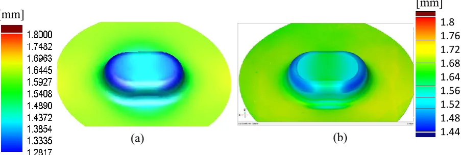
[image:5.595.153.436.293.450.2]In addition to the above initial observation, a direct comparison of the thickness distribution of the simulated part against the scan of the formed part using the GOM Atos system was performed to validate the model, as shown in Fig.7. As seen in the figure, good agreement was observed in the regions of maximum thinning and thickening and in the predicted thickness distribution between the FE model and the scan of the formed part.
Fig.6.Hydroformingstage 1 comparison with FEM; a) Profile and b) top views.
Fig.7. Thickness distribution in the part - Hydroforming stage 1 comparison of a) FEM and b) GOM scanned part.
FE Model Validation- Hydroforming Stage 2. After the second stage hydroforming trials were completed, the second FE validation phase was performed. In this section, the thickness distribution and geometry comparison between the FE simulation and the 3D scanned parts were analysed. A direct comparison of the thickness distribution of the part was performed between the simulated part and the 3D electronic scan using the GOM Atos system. Agreement was observed for the thickness distribution comparison, as shown in Fig.8.
(a)
(b)
(a) (b)
1.8 1.76 1.72 1.68 1.64 1.56 1.52 1.48 1.44 1.4
[image:5.595.65.517.498.650.2]Fig.8.Hydroforming stage 2– thickness distribution comparison of a) FEM prediction and b) GOM scanned meaurements.
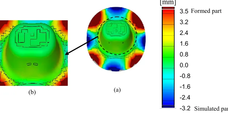
The third step to validate the FE model was performed by scanning the formed component using the GOM Atos system and overlaying it on the FE simulated part to confirm the deformation features of the part. This is shown in Fig. 9. From the figure some points can be highlighted:
The green colour indicates a perfect match between the formed and the FE simulated parts.
[image:6.595.105.470.496.677.2] The red colour indicates that the formed part is “higher” than the simulated part. The blue colour indicates that the simulation is “higher” than the formed part.
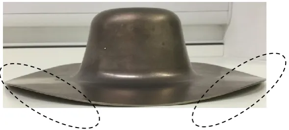
Fig.9 shows the overlaying of the GOM Atos scan of the formed part with the FE simulated part. Some differences in the flange area were observed. These were due to the distortion caused by plastic deformation and heat treatment during the experimental trials. The front view of the formed part is shown in Fig.10 to highlight these findings. However, only the first 40 mm of this flange is within the usable area of the part. Fig.9b shows a representation of the part after trimming the flange. Excellent agreement was achieved in this area of the flange between the simulated and 3D scan of the part. These results provided significant confidence in the FE model and proved that the developed FE approach predicted and represented accurately the hydroforming process and the final geometry of the formed part.
Fig.9.Hydroforming stage 2. Overlay of GOM physical component and FEM predicted model.
Simulated part 3.5
3.2 2.4 1.6 0.8 0.0 -0.8 -1.6 -2.4 -3.2 -3.5
Formed part
[mm]
(a) (b)
(a) (b)
1.75 1.65 1.575 1.5 1.425 1.35 1.275 1.2 1.15
Fig. 10. Hydroforming stage 2 Formed part showing the flange distrotion.
Conclusions
In this paper a complex shaped component has been successfully formed using a non-traditional forming process: sheet hydroforming. This paper details the development of a finite element modelling approach for this forming process. Robust material characterisation data for Inconel 718 material was generated and used to develop a FEA model. The model was validated by performing hydroforming experimental trials for a complex component using Inconel 718 sheet material. The parts produced via experimental trials to validate this model were shown to have very close agreement with the FE model.
Acknowledgment
The authors would like to thank Middleton Sheet Metal Co. Ltd (Manchester, UK) for the support and advice provided during the hydroforming trials.
For further information regarding the implementation of the process, please contact the authors.
References
[1] S. Oh, B. Jeon, H. Kim, J. Yang, Applications of hydroforming processes to automobile parts, J. Mater. Process. Tech. 174 (2006) 42-55.
[2] M.H. Parsa, P. Darbandi, Experimental and numerical analyses of sheet hydroforming process for production of an automobile body part, J. Mater. Process. Tech. 198 (2008) 381-390.
[3] M. Zampaloni, N. Abedrabbo, F. Pourboghrat, Experimental and numerical study of stamp hydroforming of sheet metals, Int. J. Mech. Sci. 45 (2003) 1815-1848
[4] N. Abedrabbo, M.A. Zampaloni, F. Pourboghrat, Wrinkling control in aluminum sheet hydroforming, Int. J. Mech. Sci. 47 (2005) 333-358.