NEAR-CAPACITY TRANSCEIVER DESIGN USING EXIT-CURVE FITTING:
THREE-STAGE TURBO DETECTION OF IRREGULAR CONVOLUTIONAL CODED JOINT
SPHERE-PACKING MODULATION AND SPACE-TIME CODING
O. Alamri, J. Wang, S. X. Ng, L.-L. Yang and L. Hanzo
∗School of ECS, University of Southampton, SO17 1BJ, UK.
Email:
[email protected]
http://www-mobile.ecs.soton.ac.uk
Abstract- Conventional two-stage turbo-detected schemes typically suffer from a Bit Error Rate (BER) floor, prevent-ing them from achievprevent-ing infinitesimally low BER values, es-pecially, when the inner coding stage is of non-recursive na-ture. We circumvent this deficiency by proposing a three-stage turbo-detected Sphere Packing (SP) aided Space-Time Block Coding (STBC) STBC-SP scheme, where a rate-1 recursive in-ner precoder is employed to avoid having a BER floor. The convergence behaviour of this serially concatenated scheme is investigated with the aid of 3D Extrinsic Information Trans-fer (EXIT) Charts. Furthermore, the capacity of the STBC-SP scheme is shown and an algorithm is proposed for calculating a tighter upper bound on the maximum achievable bandwidth efficiency. The proposed three-stage turbo-detected scheme operates within about1.0dB of the capacity and within0.5dB of the maximum achievable bandwidth efficiency limit.
1. INTRODUCTION
The concept of combining orthogonal transmit diversity designs with the principle of sphere packing was introduced by Suet al. in 2003 [1] in order to maximise the achievable coding advantage1,
where it was demonstrated that the proposed Sphere Packing (SP) aided Space-Time Block Coded (STBC) system, referred to here as STBC-SP, was capable of outperforming the conventional or-thogonal design based STBC schemes of [2, 3].The ultimate ra-tionale of this paper is to use a novel three-dimensional Extrinsic Information Transfer (EXIT)-chart-based technique to jointly de-sign the two time-slots’ STBC de-signal by near-optimally combining them into an iteratively detected SP symbol.
The turbo principle of [4] was extended to multiple serially con-catenated codes in 1998 [5]. The appeal of concon-catenated coding is that low-complexity iterative detection replaces the potentially more complex optimum decoder, such as that of [6]. In [7], the employment of the turbo principle was considered for iterative soft demapping in the context of bit-interleaved coded modula-tion (BICM), where a soft demapper was used between the mul-tilevel demodulator and the channel decoder. In [8], a turbo cod-ing scheme was proposed for the multiple-input multiple-output (MIMO) Rayleigh fading channel, where a block code was em-ployed as an outer channel code, while an orthogonal STBC scheme was considered as the inner code. The iterative soft demapping principle of [7] was extended to STBC-SP schemes in [9], where it was demonstrated that turbo-detected STBC-SP schemes provide
∗The financial support of the EPSRC, UK and that of the European Union under the Phoenix and Newcom projects as well as that of the Min-istry of Higher Education of Saudi Arabia is gratefully acknowledged.
1The diversity product or coding advantage was defined as the
esti-mated gain over an uncoded system having the same diversity order as the coded system [1].
useful performance improvements over conventionally-modulated orthogonal design based STBC schemes. It was shown in [10] that a recursive inner code is needed in order to maximise the inter-leaver gain and to avoid the formation of a bit-error rate (BER) floor, when employing iterative decoding. This principle has been adopted by several authors designing serially concatenated schemes, where rate-1 inner codes were employed for designing low com-plexity turbo codes suitable for bandwidth and power limited sys-tems having stringent BER requirements [11–13].
Recently, studying the convergence behaviour of iterative de-coding has attracted considerable attention [14–17]. In [14], ten Brink proposed the employment of the so-called EXIT character-istics between a concatenated decoder’s output and input for de-scribing the flow of extrinsic information through the soft-in/soft-out constituent decoders. The computation of EXIT charts was further simplified in [15] to a time average, for scenarii when the PDFs of the communicated information at the input and output of the constituent decoders are both symmetric and ergodic. The concept of EXIT chart analysis has been extended to three-stage concatenated systems in [16, 17].
In this paper, we propose a capacity-approaching three-stage turbo-detected STBC-SP scheme, where iterative decoding is car-ried out between three constituent decoders, namely an STBC-SP
demapper, an inner rate-1 recursiveA P osteriori P robability
(APP)-based decoder and an outer APP-based decoder. We first show the capacity limit for STBC-SP schemes. Then, an upper bound on the maximum achievable rate is calculated, based on the
EXIT charts of the STBC-SP demapper. At a spectral efficiency
ofη= 1bits/s/Hz, the upper bound of the maximum achievable rate is within0.5dB of the capacity, and our proposed three-stage scheme operates within1.0dB of the capacity. The ra-tionale of the proposed architecture is explicit: (1) SP modula-tion maximises the coding advantage of the transmission scheme by jointly designing and detecting the SP symbols hosting the two time-slots’ STBC symbols; (2) the inner rate-1 recursive de-coder maximises the interleaver gain and hence avoids having a BER floor; and (3) the outer irregular convolutional codes (IR-CCs) [15, 18] minimise the area of the EXIT chart’s convergence tunnel and hence facilitate near-capacity operation [19].
Outer Encoder
I
1 Encoder
Rate-1
II
Sphere
Mapper Packing
Encoder STBC
Decoder STBC Demapper
Sphere Packing
2
−1 2
1
−1 1
2 Source
Binary
Hard Decision
T x1
T x2
Rx1
RxN
SISO SISO
Decoder I Decoder II
u1
LI,a(c1)
LI,e(u1) LII,e(u2) LII,a(c2)LM,e(u3)
r s c2 u3
u2
c1
LI,e(c1) LII,a(u2) LII,e(c2)LM,a(u3)
ˆ
[image:2.595.64.281.70.144.2]u1
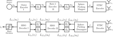
Figure 1:Three-stage serially concatenated system.
2. SYSTEM OVERVIEW
The schematic of the entire system is shown in Fig. 1, where the transmitted source bitsu1are encoded by the outer channel
En-coder I having a rate ofRI. The outer channel encoded bitsc1
are then interleaved by the first random bit interleaver, where the randomly permuted bitsu2 are fed through the rate-1 Encoder II. The concatenated coded bitsc2at the output of the rate-1 en-coder are interleaved by the second random bit interleaver, produc-ing the permuted bitsu3. After channel interleaving, the sphere
packing mapper first maps blocks ofBchannel-coded bitsb = b0,...,B−1 ∈ {0,1}to the L = 2B number of legitimate four-dimensional sphere packing modulated symbolssl ∈S, whereS ={sl= [al,1al,2al,3al,4]∈R4:0≤l≤L−1}constitutes a set ofLlegitimate constellation points from the latticeD4[20] having
a total energy ofE=lL=0−1(|al,1|2+|al,2|2+|al,3|2+|al,4|2).
The STBC encoder then maps each sphere packing modulated symbolslto a space-time signalClas [1, 9]:
Cl=
2L
EG2(xl,1, xl,2), 0≤l≤L−1, (1) wherexl,1andxl,2are complex-valued symbols constructed from
the4-dimensional real-valued coordinates of the SP symbolslin
order to maximise the coding advantage of the space-time signal Cl[1], since the latticeD4has the best minimum Euclidean dis-tance in the four-dimensional real-valued Euclidean spaceR4[20]. Specifically, xl,1and xl,2 may be written as {xl,1, xl,2}=
Tsp(al,1, al,2, al,3, al,4) =al,1+jal,2, al,3+jal,4.
Further-more,G2(xl,1, xl,2)is the space-time transmission matrix given
by [2]
G2(x1, x2) =
x1 x2 −x∗
2 x∗1
, (2)
where the rows and columns of Eq. (2) represent the temporal and spatial dimensions, corresponding to two consecutive time slots and two transmit antennas, respectively.
In this treatise, we considered a correlated narrowband Rayleigh fading channel, associated with a normalised Doppler frequency offD = fdTs = 0.1, wherefd is the Doppler frequency and
Tsis the symbol period. The complex-valued fading envelope is
assumed to be constant across the transmission period of a space-time coded symbol spanningT= 2time slots. The complex Ad-ditive White Gaussian Noise (AWGN) ofn=nI+jnQis also
added to the received signal, wherenIandnQare two
indepen-dent zero-mean Gaussian random variables having a variance of σ2
n = σn2I = σn2Q = N0/2per dimension, whereN0/2
repre-sents the double-sided noise power spectral density expressed in W/Hz.
As shown in Fig. 1, the received complex-valued symbols are first decoded by the STBC decoder in order to produce the received SP soft-symbolsr, where each SP symbol represents a block of Bcoded bits [9]. Then, iterative demapping/decoding is carried out between the SP demapper, APP-based soft-in/soft-out (SISO) module II and APP-based SISO module I, where extrinsic informa-tion is exchanged between the three constituent demapper/decoder
modules. More specifically, L·,a(·) in Fig. 1 represents the a
prioriinformation, expressed in terms of the log-likelihood ra-tios (LLRs) of the corresponding bits, whereasL·,e(·)represents
theextrinsicLLRs of the corresponding bits. The iterative pro-cess is performed for a number of consecutive iterations. During the last iteration, only the LLR values LI,e(u1)of the original uncoded systematic information bits u1 are required, which are
passed to a hard decision decoder in order to determine the esti-mated transmitted source bitsuˆ1as shown in Fig. 1.
3. EXIT CHART ANALYSIS
3.1. Preliminaries
The main objective of employing EXIT charts [14], is to predict the convergence behaviour of the iterative decoder by examining the evolution of the input/output mutual information exchange be-tween the inner and outer decoders in consecutive iterations. The application of EXIT charts is based on the two assumptions that upon assuming large interleaver lengths, (1) thea prioriLLR val-ues are fairly uncorrelated; (2) thea prioriLLR values exhibit a Gaussian PDF. In this section, the approach presented in [17] is adopted in order to provide the EXIT chart analysis of the pro-posed three-stage system of Fig. 1.
LetI·,a(x),0≤ I·,a(x) ≤ 1, denote the mutual information
(MI) between the a prioriLLRsL·,a(x)as well as the
corre-sponding bitsxand letI·,e(x),0≤I·,e(x)≤1, denote the MI
between theextrinsicLLRsL·,e(x)and the corresponding bits
x, where the subscript(·)is used to distinguish the different con-stituent decoders, i.e. Decoder I, Decoder II and the SP demapper.
3.2. 3D EXIT Charts
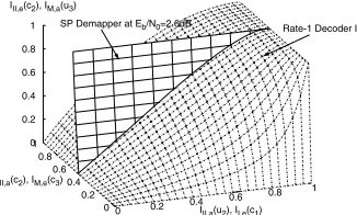
As seen from Fig. 1, the input of Decoder II is constituted by the a prioriinputLII,a(c2)and thea prioriinputLII,a(u2) pro-vided after bit-deinterleaving by the SP demapper and Decoder I, respectively. Therefore, the EXIT characteristic of Decoder II can be described by the following two EXIT functions [14, 17]:
III,e(c2) = TII,c2(III,a(u2), III,a(c2)), (3)
III,e(u2) = TII,u2(III,a(u2), III,a(c2)), (4)
which are illustrated by the 3D surfaces drawn in dotted lines in Figs. 2 and 3, respectively. On the other hand, the EXIT charac-teristic of the SP demapper as well as that of Decoder I are each dependent on a singlea prioriinput, namely onLM,a(u3)and
LI,a(c1), respectively, both of which are provided by the rate-1
Decoder II after appropriately ordering the bits, as seen in Fig. 1. The EXIT characteristic of the SP demapper is also dependent on theEb/N0value. Consequently, the corresponding EXIT func-tions for the SP demapper and Decoder I, respectively, may be written as
IM,e(u3) = TM,u3(IM,a(u3), Eb/N0), (5) II,e(c1) = TI,c1(II,a(c1)), (6)
which are illustrated by the 3D surfaces drawn in solid lines in Figs. 2 and 3, respectively.
(Gr, G) = (3,2)8, whereGris the feedback polynomial, while
Encoder II is a simple rate-1 accumulator, described by the pair of octal generator polynomials(G/Gr) = (2/3)8.
SP Demapper at Eb/N0=2.0dB Rate-1 Decoder II
0 0.2 0.4
0.6 0.8
1
III,a(u2), II,e(c1)
0 0.2 0.4 0.6 0.8 1
III,a(c2), IM,e(c3)
0 0.2 0.4 0.6 0.8 1
[image:3.595.92.255.109.207.2]III,e(c2), IM,a(u3)
Figure 2:3D EXIT chart of Decoder II and the SP demapper atEb/N0= 2.0dB.
Rate-1 Decoder II
Outer Decoder I
0 0.2
0.4 0.6 0.8
1
III,a(u2), II,e(c1)
0 0.2 0.4 0.6 0.8 1
III,a(c2), IM,e(c3)
0 0.2 0.4 0.6 0.8 1
[image:3.595.93.260.245.350.2]III,e(u2), II,a(c1)
Figure 3:3D EXIT chart of Decoder II and Decoder I with projection from Fig. 2.
3.3. 2D EXIT Chart Projections
The 3D EXIT charts of Figs. 2 and 3 are somewhat cumbersome to interpret as well as to plot. Hence in this section we derive their unique and unambiguous 2D representations, which can be interpreted in the usual way.
The intersection of the surfaces in Fig. 2, shown as a thick solid line, portrays the best achievable performance, when exchanging mutual information between the SP demapper and the rate-1 De-coder II for different fixed values ofIII,a(u2)spanning the range of [0,1]. Each(III,a(u2), III,a(c2), III,e(c2)) point belong-ing to the intersection line in Fig. 2 uniquely specifies a 3D point (III,a(u2),III,a(c2),III,e(u2))in Fig. 3, according to the EXIT
function of Eq. (4). Therefore, the line corresponding to the (III,a(u2), III,a(c2), III,e(c2))points along the thick line of Fig. 2 is projected to the solid line shown in Fig. 3, while the 2D projection of the solid line in Fig. 3 atIII,a(c2) = 0onto the plane spanned by the lines(III,a(u2), III,e(u2))and(II,e(c1), II,a(c1))
is shown in Fig. 4-a, represented by the dotted line atEb/N0 =
2.0dB. This projected EXIT curve may be written as
III,e(u2) =TII,up 2(III,a(u2), Eb/N0). (7)
Projected 2D EXIT charts of similar nature will be used throughout the rest of the paper for the sake of describing the convergence be-haviour of the three-stage turbo-detected STBC-SP scheme. More details on the related 3D-to-2D EXIT chart projection are provided in [17].
Fig. 4-a shows the 2D-projected EXIT curve of the SP demap-per, when operating atEb/N0= 2.0dB and employing Anti-Gray Mapping2(AGM-1) scheme, which is described in Appendix A
2Anti-Gray Mapping (AGM) is used here to refer to any non-Gray
map-ping scheme, while the specific scheme AGM-1 and other AGM schemes employed in this paper are described in Appendix A and Table 1.
and in Table 1. The figure also shows the 2D-projected EXIT curve of the outer RSC Decoder I and the 2D-projected EXIT curves of the combined SP demapper and the rate-1 Decoder II at differ-entEb/N0values, when employing AGM-1 of Table 1. Observe in Fig. 4-a that an open convergence tunnel is taking shape for the three-stage scheme upon increasing the Signal-to-Noise Ra-tio (SNR) beyondEb/N0 = 2.0dB. This implies that according
to the predictions of the 2D EXIT chart seen in Fig. 4-a, the it-erative decoding process is expected to converge to the(1.0,1.0) point and hence an infinitesimally low BER may be attained be-yondEb/N0 = 2.0dB. By contrast, for the traditional two-stage turbo-detected STBC-SP scheme, there would be a BER floor pre-venting it from achieving an infinitesimally low BER due to the non-recursive nature of the SP demapper, which also prevents the intersection of the EXIT curves of the SP demapper and the outer RSC Decoder I from reaching the(1.0,1.0)point of convergence, despite increasing the SNR or the number of iterations. In con-trast to this, the three-stage scheme of Fig. 1 becomes capable of achieving an infinitesimally low BER, as suggested by the EXIT-chart predictions of Fig. 4-a.
0.0 0.2 0.4 0.6 0.8 1.0 IM,a(u3), III,a(u2), II,e(c1)
0.0 0.2 0.4 0.6 0.8 1.0
IM,e
(c3
),
III,e
(u2
),
II,a
(c1
)
(a)
. . . .
. .
STBC-SP, L=16AGM-1, Eb/N0=2.0dB
RSC (2,1,2)
Projection:
Eb/N0=2.0dB
Eb/N0=2.5dB
Eb/N0=3.0dB
.
0.0 0.2 0.4 0.6 0.8 1.0 IM,a(u3), III,a(u2), II,e(c1)
0.0 0.2 0.4 0.6 0.8 1.0
IM,e
(c3
),
III,e
(u2
),
II,a
(c1
)
(b)
. . .
. . .
. . .
. .
STBC-SP, L=16AGM-2, Eb/N0=1.5dB
IRCC
Projection:
Eb/N0=1.5dB
Eb/N0=1.8dB Eb/N0=2.5dB
.
Figure 4:2D projection of the EXIT charts of the three-stage STBC-SP scheme. (a) RSC-coded STBC-SP scheme with AGM-1 of Table 1. (b) IRCC-coded STBC-SP scheme with AGM-2 of Table 1.
3.4. EXIT Tunnel-Area Minimisation for Near-Capacity Op-eration
In this section we will exploit the well-understood properties of conventional 2D EXIT charts that a narrow and open EXIT-tunnel represents a near-capacity performance. Therefore, we invoke Ir-regular Convolutional Codes (IRCCs) for the sake of appropriately shaping the EXIT curves by minimising the area within the EXIT-tunnel using the procedure of [15, 18].
LetAIandA¯Ibe the areas under the EXIT-curveTI,c1(i)of
Eq. (6) and its inverseTI,c−11(i),i ∈[0,1], respectively, which is expressed as:
AI=
1
0 TI,c1
(i)di, A¯I=
1
0 T
−1
I,c1(i)di = 1−AI. (8)
Similarly, the areaApIIis defined under the EXIT-curveTII,up 2(i) of Eq. (7). It was observed in [15, 21] that for the APP-based outer Decoder I, the areaA¯Imaybe approximated byA¯I≈RI, where
the equalityA¯I =RIwas later shown in [19] for the family of
Binary Erasure Channels (BECs). The area property ofA¯I≈RI
implies that the lowest SNR convergence threshold occurs, when we haveApII=RI+, whereis an infinitesimally small number,
provided that the following convergence constraints hold [18]:
Tp
II,u2(0)>0, T
p
II,u2(1) = 1, T
p
II,u2(i)> T −1
I,c1(i),∀i∈[0,1).
[image:3.595.306.531.276.390.2]EXIT curveTI,c−11(i)of the outer1/2-rate RSC code atEb/N0=
2.0dB. This implies that the BER curve is farther from the achiev-able capacity than necessary, despite the fact that the specific bit-to-SP-symbol mapping scheme of AGM-1 and the1/2-rate RSC code employed in Fig. 4-a were specifically optimised for conver-gence at a lowEb/N0value. More quantitatively, the area under
the projected EXIT curveTII,up 2(i)isAIIp ≈0.55atEb/N0 =
2.0dB, which is larger than the outer code rate ofRI = 0.50.
Therefore, according to Fig. 4-a and to the area property ofA¯I≈
RI, a lowerEb/N0convergence threshold may be attained, pro-vided that the constraints outlined in Eq. (9) are satisfied. In other words, the EXIT curveTI,c−11(i)of the outer code should match the 2D-projected EXIT curveTII,up 2(i)of Fig. 4-a more closely. Hence we will invoke IRCCs [15, 18] as outer codes that exhibit flexible EXIT characteristics, which can be optimised to more closely match the 2D-projected EXIT curveTII,up 2(i)of Fig. 4-a, rendering the near-capacity code optimisation a simple curve-fitting process.
An IRCC scheme constituted by a set ofP = 17subcodes was constructed in [18] from a systematic1/2-rate memory-4mother code defined by the octally represented generator polynomials(Gr,
G) = (23,35)8. Each of theP = 17subcodes encodes a specific
fraction of the uncoded bits determined by the weighting coeffi-cient,αi,i= 0, . . . , P. Hence the coefficientsαiare optimised
with the aid of the iterative algorithm of [15], so that the EXIT curve of the resultant IRCC closely matches the 2D-projected EXIT curveTII,up 2(i)at the specificEb/N0value, where we haveApII≈ 0.50. Observe in Fig. 4-b that we haveAp
II ≈0.51atEb/N0=
1.5dB, indicating that thisEb/N0value is close to the lowest at-tainable convergence threshold, when employing a1/2-rate outer code. Fig. 4-b also shows the 2D-projected EXIT curve of the re-sultant IRCC, where the optimised weighting coefficients are as follows:
[α1, . . . , α17] = [0,0.0559066,0.236757,0,0,0,
0.23844,0,0,0.0306247,0,0.205574, 0,0,0.110076,0,0.122621]. (10)
4. CAPACITY AND MAXIMUM ACHIEVABLE RATE
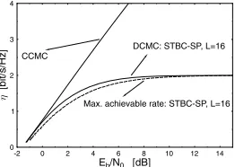
The channel capacity and bandwidth efficiency valid for STBC schemes usingND-dimensional so-calledL-orthogonal signalling
[22] over the Discrete-input Continuous-output Memoryless Chan-nel (DCMC) [23] was derived in [24]. Fig. 5 shows the DCMC bandwidth efficiencyηDCM CST BC−SP of the4-dimensional SP mod-ulation assisted STBC scheme forL = 16, where the Continu-ous-Input Continuous-Output Memoryless Channel (CCMC) [23] capacity of the MIMO scheme is given by [25]. More specifi-cally, Fig. 5 demonstrates that at a bandwidth efficiency ofη = 1bit/s/Hz, the capacity limit for the DCMC STBC-SP scheme employingNt = 2 transmit andNr = 1receive antennas is
Eb/N0= 0.78dB. The EXIT chart analysis of Fig. 4-b predicts that our three-stage system will converge atEb/N0= 1.5dB, i.e.
within0.72dB from the capacity limit. The dotted curve referring to the maximum achievable rate of the three-stage turbo-detected STBC-SP scheme is discussed next.
A tighter upper limit on the maximum achievable rate of the system can be calculated based on the area property ofA¯I ≈RI
of EXIT charts as discussed in Section 3.4. More explicitly, it was shown in Section 3.4 that the outer Decoder I may have a maximum rate ofRmax
I ≈ ApIIat a specificEb/N0value, where
Ap
IIis the area under the projected EXIT curve of the SP demapper
and the rate-1 Decoder II of Eq. (7). Therefore, ifApIIis calculated for differentEb/N0values, the maximum achievable bandwidth
-2 0 2 4 6 8 10 12 14
Eb/N0 [dB] 0
1 2 3 4
[bit/s/Hz]
CCMC
DCMC: STBC-SP, L=16
[image:4.595.351.482.63.156.2]Max. achievable rate: STBC-SP, L=16
Figure 5:Bandwidth efficiency of the STBC-SP based system withL= 16, when employingNt= 2transmit antennas andNr= 1receive antenna.
efficiency may be formulated as a function of theEb/N0value as
follows
ηmax(Eb/N0) = B·RST BC−SP·RmaxI
≈ B·RST BC−SP· ApII(Eb/N0) [bit/s/Hs],
(11)
whereB = log2(L)is the number of bits per SP symbol and RST BC−SP = 12, sinceT = 2time slots are needed to transmit
one SP symbol according to Eqs. (1) and (2). Additionally,Eb/N0
andEb/N0are related as follows
Eb/N0=Eb/N0+ 10 log Ap Ro II(Eb/N0)
[dB], (12)
whereRois the original outer code rate used when generating the
2D-projected EXIT curves of the SP demapper and the rate-1 De-coder II of Eq. (7) corresponding to the differentApIIvalues. A simple procedure may be used to calculate the maximum achiev-able bandwith efficiency of Eq. (11). For computational simplic-ity, the areaAM under the EXIT curve TM,u3 of Eq. (5) may
be used instead of the areaApII under the 2D-projected EXIT curveTII,up 2 of Eq. (7), since AM = ApII, when RII = 1.
More specifically, the maximum achievable bandwith efficiency of Eq. (11) can be calculated using the following procedure for Eb/N0∈[ρmin, ρmax], assuming thatRois an arbitrary rate and
is a small constant.
Algorithm 1 (Maximum Achievable Bandwidth Efficiency using EXIT Charts):
Step 1: LetRI=Ro.
Step 2: LetEb/N0=ρmindB.
Step 3: CalculateN0. Step 4: LetIM,a(u3) = 0.
Step 5: Activate the SP demapper.
Step 6: SaveIM,e(u3) =TM,u3(IM,a(u3), Eb/N0).
Step 7: LetIM,a(u3) = IM,a(u3) +. IfIM,a(u3)≤
1.0, go to Step5.
Step 8: CalculateAM(Eb/N0) =01TM,u3(i, Eb/N0)di. Step 9: CalculateEb/N0using Eq. (12).
Step 10: Saveηmax(Eb/N0)of Eq. (11).
Step 11: LetEb/N0=Eb/N0+. IfEb/N0≤ρmaxdB,
go to Step3.
Step 12: Outputηmax(Eb/N0)from Step10.
Observe thatρminandρmaxare adjusted accordingly in order to
produce the desired range of the resultantEb/N0 values.
Fur-thermore, the output of Algorithm1is independent of the specific choice ofRo, since Eq. (12) would always adjust theEb/N0 val-ues, regardless ofRo. For example,Romay be set to the desired
The resultant maximum achievable bandwidth efficiency is dem-onstrated in Fig. 5, which is slightly lower than the bandwidth efficiency calculated according to [24], i.e. we haveηmax <
ηST BC−SP
DCM C . Observe that the bandwidth efficiency calculated
[image:5.595.331.485.74.227.2]ac-cording to [24] and using the EXIT charts as well as Eq. (11) were only proven to be equal for the family of BECs [19]. Nonethe-less, similar trends have been observed for both AWGN and Inter-Symbol-Interference (ISI) channels [16, 18], when APP-based de-coders are used for all decoder blocks [19]. However, the dis-crepancy between the two bandwidth efficiency curves shown in Fig. 5 is due to the fact that the SP demapper is not an APP-based decoder. Nevertheless, the bandwidth efficiency calculated based on the EXIT charts using Eq. (11) and Algorithm1constitutes a tighter bound on the maximum achievable bandwidth efficiency of the system.
Fig. 5 shows that at a bandwidth efficiency ofη= 1bit/s/Hz, the capacity limit for the STBC-SP scheme is aboutEb/N0 =
1.3dB, which is within0.2dB from the prediction of our EXIT chart analysis seen in Fig. 4-b, where convergence is predicted at Eb/N0= 1.5dB.
5. RESULTS AND DISCUSSIONS
5.1. System Parameters
Without loss of generality, we considered a sphere packing mod-ulation scheme associated withL = 16using two transmit and a single receiver antenna in order to demonstrate the performance improvements achieved by the proposed system. The communica-tion channel is described in Seccommunica-tion 2, while the outer Encoder I is a half-rate memory-4 IRCC constructed usingP = 17subcodes according to the weighting coefficients of Eq. (10). Encoder II is a simple rate-1 accumulator, described by the pair of octal generator polynomials(G/Gr) = (2/3)8. A three-stage iteration involves the following decoder activation sequence: (SP Demapper - De-coder II - SP Demapper - DeDe-coder II - DeDe-coder I - DeDe-coder II). The overall system throughput is1bit/symbol.
5.2. Decoding Trajectory and BER Performance
EXIT chart based convergence predictions are usually verified by the actual iterative decoding trajectory. Fig. 4-b shows that the three-stage turbo-detected STBC-SP scheme is expected to con-verge atEb/N0 = 1.5dB, where convergence to the(1.0,1.0) point requires an excessive number of three-stage iterations. How-ever, convergence to the(1.0,1.0)point becomes more feasible forEb/N0>1.5dB. Fig. 6 illustrates the actual decoding
[image:5.595.319.501.465.603.2]trajec-tory of the three-stage turbo-detected STBC-SP scheme of Fig. 1 atEb/N0= 1.8dB, when using an interleaver depth ofD= 106 bits and33three-stage iterations. The zigzag-path seen in Fig. 6 represents the actual extrinsic information transfer between the SP demapper and the rate-1Decoder II on one hand and the outer IRCC Decoder I on the other.
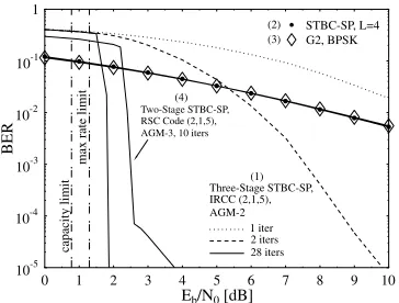
Fig. 7 compares the performance of the proposed three-stage IRCC-coded STBC-SP scheme employing anti-Gray mapping (AGM-2) against that of an identical-throughput 1 Bit Per Symbol (1BPS) uncoded STBC-SP scheme [1] usingL = 4and against Alamouti’s conventionalG2-BPSK scheme [2]. The system is
also benchmarked against a two-stage RSC-coded STBC-SP scheme [9], when employing the system parameters outlined in Section 5.1 and using an interleaver depth ofD= 106bits. Fig. 7 specifically demonstrates that the proposed three-stage turbo-detected scheme is capable of achieving infinitesimally low BER values, where its performance is not limited by a BER floor, which is in contrast to the two-stage turbo-detected STBC-SP scheme. Observe that the two-stage turbo-detected STBC-SP scheme uses
0.0 0.2 0.4 0.6 0.8 1.0
IM,a(u3), III,a(u2), II,e(c1)
0.0 0.2 0.4 0.6 0.8 1.0
IM,e
(c3
),
III,e
(u2
),
II,a
(c1
)
STBC-SP, L=16
AGM-2,
E
b/N
0=1.8dB
IRCC Projection Decoding trajectory
(Interleaver depth = 106bits)
Figure 6: Decoding trajectory of the three-stage IRCC-coded STBC-SP scheme, when employing the anti-Gray mapping AGM-2 of Table 1 in combination with the system parameters outlined in Section 5.1 and operating atEb/N0= 1.8dB with an interleaver depth ofD= 106bits after33three-stage iterations.
only10iterations since the advantage of employing any further it-erations diminishes owing to the presence of a BER floor. Explic-itly, Fig. 7 demonstrates that a coding advantage of about22.2dB was achieved at a BER of10−5after28iterations by the three-stage turbo-detected SP system over both the uncoded STBC-SP [1] and the conventional orthogonal STBC design based [2, 3] schemes for transmission over the correlated Rayleigh fading channel considered. Additionally, a coding advantage of approxi-mately2.0dB was attained over the 1BPS-throughput RSC-coded AGM-3 STBC-SP scheme [9] at the expense of an increased de-coding complexity due to the employment of the rate-1decoder and the additional three-stage iterations. According to Fig. 7, the three-stage turbo-detected STBC-SP scheme operates within ap-proximately1.0dB from the capacity limit calculated from [24] and0.5dB from the maximum achievable bandwidth efficiency limit of Eq. (11).
0 1 2 3 4 5 6 7 8 9 10
Eb/N0[dB] 10-5
10-4 10-3 10-2 10-1 1
BER
. . . .
. . . .
.
.
STBC-SP, L=4G2, BPSK
capacity
limit
max
rate
limit Two-Stage STBC-SP, RSC Code (2,1,5), AGM-3, 10 iters
Three-Stage STBC-SP, IRCC (2,1,5), AGM-2
1 iter 2 iters 28 iters (1) (4)
(2) (3)
Figure 7: Performance comparison of the anti-Gray mapping AGM-2(1)based IRCC-coded three-stage STBC-SP scheme in conjunction withL= 16against an identical-throughput 1 bit/symbol (BPS) uncoded STBC-SP scheme(2)usingL=
4and against Alamouti’s conventionalG2-BPSK scheme(3)as well as against a two-stage RSC-coded STBC-SP scheme(4), when employing the system parameters outlined in Section 5.1 and using an interleaver depth ofD= 106bits.
6. CONCLUSION
BER values, where the performace is not limited by a BER floor, which is routinely encountered in conventional two-stage systems. The convergence behaviour of the three-stage system was anal-ysed with the aid of novel 3D EXIT charts and their 2D projec-tions [16, 17]. With the advent of 2D projecprojec-tions, an IRCC [15, 18] was constructed for the sake of matching the projected EXIT curve of the SP demapper and the rate-1inner decoder leading to a near-capacity performance. The near-capacity of the STBC-SP scheme was calculated and a procedure was proposed for calculating a tighter upper bound on the maximum achievable bandwidth efficiency of the three-stage system using EXIT chart analysis. Our proposed three-stage scheme operated within about1.0dB from the capacity limit and within0.5dB from the maximum achievable bandwidth efficiency limit.
Appendix A
Anti-Gray Mapping Schemes for Sphere Packing
Modulation of Size
L
= 16
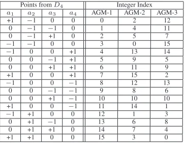
In this appendix, the different anti-Gray mapping (AGM) sch-emes introduced in this paper for STBC-SP signal sets of size L= 16are described. There are more thanL = 16legitimate SP symbols in the latticeD4and hence the requiredL= 16SP
symbols were chosen according to the minimum energy and high-est minimum Euclidean distance (MED) criterion proposed in [9]. All mapping schemes described here use the same16optimum constellation points. More specifically, for all mapping schemes, constellation points of the latticeD4 are given for each integer
indexl= 0,1, . . . ,15. The normalisation factor of these constel-lation points is
2L
E = 1. The constellation points corresponding
to each mapping scheme are given in Table 1.
Points fromD4 Integer Index
a1 a2 a3 a4 AGM-1 AGM-2 AGM-3
+1 −1 0 0 0 2 12
0 −1 −1 0 1 4 11
0 −1 +1 0 2 5 7
−1 −1 0 0 3 0 15
−1 0 0 +1 4 13 14
0 0 −1 +1 5 9 5
0 0 +1 +1 6 11 9
+1 0 0 +1 7 15 2
−1 0 0 −1 8 12 13
0 0 −1 −1 9 8 6
0 0 +1 −1 10 10 10
+1 0 0 −1 11 14 1
−1 +1 0 0 12 1 3
0 +1 −1 0 13 6 8
0 +1 +1 0 14 7 4
[image:6.595.84.266.392.532.2]+1 +1 0 0 15 3 0
Table 1: Bit mappings for the different anti-Gray mapping schemes introduced for STBC-SP signals of sizeL= 16.
7. REFERENCES
[1] W. Su, Z. Safar, and K. J. R. Liu, “Space-time signal design for time-correlated Rayleigh fading channels,” inIEEE International Confer-ence on Communications, vol. 5, (Anchorage, Alaska), pp. 3175– 3179, 2003.
[2] S. Alamouti, “A simple transmit diversity technique for wireless communications,”IEEE Journal on Selected Areas in Communica-tions, vol. 16, no. 8, pp. 1451–1458, 1998.
[3] V. Tarokh, H. Jafarkhani, and A. Calderbank, “Space-time block codes from orthogonal designs,”IEEE Transactions on Information Theory, vol. 45, pp. 1456–1467, Jul 1999.
[4] C. Berrou, A. Glavieux, and P. Thitimajshima, “Near Shannon limit error-correcting coding and decoding: Turbo codes,”Proceedings of the IEEE International Confrence on Communications, pp. 1064– 1070, May 1993.
[5] S. Benedetto, D. Divsalar, G. Montorsi, and F. Pollara, “Analysis, design, and iterative decoding of double serially concatenated codes with interleavers,”IEEE Journal on Selected Areas in Communica-tions, vol. 16, no. 2, pp. 231–244, 1998.
[6] M. Breiling and L. Hanzo, “The super-trellis structure of turbo codes,”IEEE Transactions on Information Theory, vol. 46, pp. 2212– 2228, Sep 2000.
[7] S. ten Brink, J. Speidel, and R.-H. Yan, “Iterative demappping and decoding for multilevel modulation,” inIEEE Global Telecommuni-cations Conference, vol. 1, (Sydney, Australia), pp. 579–584, 8-12 Nov 1998.
[8] A. Sezgin, D. Wuebben, and V. Kuehn, “Analysis of mapping strate-gies for turbo-coded space-time block codes,” inProceedings of IEEE Information Theory Workshop, pp. 103–106, March 2003.
[9] O. Alamri, B. L. Yeap, and L. Hanzo, “Turbo detection of channel-coded space-time signals using sphere packing modulation,” inIEEE Vehicular Technology Conference, vol. 4, (Los Angeles, USA), pp. 2498–2502, Sep 2004.
[10] S. Benedetto, D. Divsalar, G. Montorsi, and F. Pollara, “Serial concatenation of interleaved codes: performance analysis, design, and iterative decoding,”IEEE Transactions on Information Theory, vol. 44, no. 3, pp. 909–926, 1998.
[11] D. Divsalar, S. Dolinar, and F. Pollara, “Serial concatenated trellis coded modulation with rate-1 inner code,” inIEEE Global Telecom-munications Conference, vol. 2, (San Francisco, USA), pp. 777–782, 27 Nov-1 Dec 2000.
[12] K. Narayanan, “Effect of precoding on the convergence of turbo equalization for partial response channels,”IEEE Journal on Selected Areas in Communications, vol. 19, pp. 686–698, April 2001.
[13] I. Lee, “The effect of a precoder on serially concatenated coding sys-tems with an ISI channel,”IEEE Transactions on Communications, vol. 49, pp. 1168–1175, Jul 2001.
[14] S. ten Brink, “Designing iterative decoding schemes with the extrin-sic information transfer chart,”AE¨UInternational Journal of Elec-tronics and Communications, vol. 54, pp. 389–398, Nov 2000.
[15] M. T¨uchler and J. Hagenauer, “EXIT charts of irregular codes,” in
Proceedings of the 36th Annual Conference on Information Science and Systems, CISS 2002, (Princeton), March 2002.
[16] M. T¨uchler, “Convergence prediction for iterative decoding of three-fold concatenated systems,” inIEEE Global Telecommunications Conference. GLOBECOM ’02, vol. 2, pp. 1358–1362, Nov 2002.
[17] F. Br¨annstr¨om, L. Rasmussen, and A. Grant, “Convergence analy-sis and optimal scheduling for multiple concatenated codes,”IEEE Transactions on Information Theory, vol. 51, no. 9, pp. 3354–3364, 2005.
[18] M. T¨uchler, “Design of serially concatenated systems depending on the block length,”IEEE Transactions on Communications, vol. 52, pp. 209–218, Feb 2004.
[19] A. Ashikhmin, G. Kramer, and S. ten Brink, “Extrinsic informa-tion transfer funcinforma-tions: model and erasure channel properties,”IEEE Transactions on Information Theory, vol. 50, no. 11, pp. 2657–2673, 2004.
[20] J. H. Conway and N. J. Sloane, Sphere Packings, Lattices and Groups. Springer-Verlag, 1999.
[21] A. Ashikhmin, G. Kramer, and S. ten Brink, “Extrinsic information transfer functions: A model and two properties,” in36th Annual Con-ference on Information Sciences and Systems (CISS), (Princeton, NJ, USA), Mar. 2002.
[22] L. Hanzo, S. X. Ng, T. Keller, and W. T. Webb,Quadrature Am-plitude Modulation: From Basics to Adaptive Trellis-Coded, Turbo-Equalised and Space-Time Coded OFDM, CDMA and MC-CDMA Systems. John Wiley and Sons Ltd, 2 ed., Sep 2004.
[23] J. Proakis,Digital communications. McGraw-Hill, 2001.
[24] S. X. Ng and L. Hanzo, “On the MIMO channel capacity of multidi-mensional signal sets,”IEEE Transactions on Vehicular Technology, vol. 55, no. 2, pp. 528–536, 2006.