UNIVERSITI TEKNIKAL MALAYSIA MELAKA
THE THEORETICAL OF DIMENSIONAL MEASUREMENT BY
VISION SYSTEM
This report submitted in accordance with requirement of the Universiti Teknikal Malaysia Melaka (UTeM) for the Bachelor Degree of Engineering Technology
(Bachelor of Electronic Engineering Technology) (Industrial Electronic) (Hons.)
by
MEOR AZIZUL FITRI BIN AMINURASHID B071310230
910429-08-5119
i
ABSTRAK
ii
ABSTRACT
iii
DEDICATION
iv
ACKNOWLEDGMENTS
First and foremost, I want to express my most noteworthy appreciation to my supervisor, En. Ir. Nik Azran Bin Abdul Hadi for the guidance, inspiration, enthusiasm and motivation given all through the advancement of this project. Without his support and interest, this project would not be successfully accomplished as presented here.
v
TABLE OF CONTENT
Abstrak i
Abstract ii
Dedication iii
Acknowledgement iv
Table of Content v
List of Tables vi
List of Figures vii
List Abbreviations, Symbols and Nomenclatures viii
CHAPTER 1: INTRODUCTION
1.0 Introduction 1
1.1 Project Background 1
1.2 Problem Statement 2
1.3 Objectives 2
1.4 Scope of Study 3
1.5 Project Outline 3
CHAPTER 2: LITERATURE REVIEW 4
2.1 Introduction 4
2.1.1 Important of dimensional measurement 6
2.2 Theoretical of dimensional measurement (eye) 8
2.3 Object Distance and measurement 9
2.4 Size measurement 9
2.5 Object identification 10
2.6 Dimensional measurement of vision system in industrial 10
2.7 Inspection application 11
CHAPTER 3: METHODOLOGY 12
3.1 Introduction 12
vi
3.3 Problem Solving 14
3.4 Single Vision Setup 15
3.5 Coding Development 16
3.6 Simulation and testing 16
3.7 Documentation and reporting 16
3.8 Software development 16
3.9 Mathlab software 17
3.10 Pre-Processing of Project 18
3.11 Process of project 18
3.12 Post processing project 19
3.13 Camera 20
3.14 Camera Web Cam 20
3.15 Sample screw inspection 21
CHAPTER 4: RESULT AND DISCUSSION 22
4.0 Result and discussion 22
4.1 Effect of DPI on image captured and measured 22
4.1.1 Effect of background image 23
4.1.2 Effect of image PPI 25
4.2 Smallest object to be measured 26
CHAPTER 5: CONCLUSION 29
5.0 Conclusion 29
5.1 Recommendation 29
vii
LIST OF TABLES
3.1 Specification CCD camera 20
4.1 Camera distance due to measurement reading 25
4.2 Measuring ability to tinest 27
viii
LIST OF FIGURES
1.1 Human eye error of reading measurement 2
2.1 Trigonometri Measurement 7
2.2 Human eye error of reading measurement 8
2.3 Camera analyze height measurement 11
3.1 Methodology materials 13
3.2 Project flowchart 14
3.3 Camera Position 15
4.1 Tested different DPI 23
4.2 Examples of the cleaned image 24
4.3 Comparison of the image with cleaned background 24 and with background
ix
LIST OF ABBREVIATIONS, SYMBOLS AND
1 1.0 Introduction
This chapter provides an overview of the inspection system done by the industries. The problem background and problem statement are described next. This is followed by research objectives and scope of the study which involves the research study of theoretical dimensional measurement by vision system using MATLAB software.
1.1 Background
Product visual inspection is still manually or semi-automatically in most industries. Some sophisticated optical inspection methods have already been developed in recent years. Quality is one of the most important factors because it is related to customer satisfactory and its interchangeability. This project is aimed to present intelligent visual inspection system which it is compared with human that can operate untiringly and provide consistent quality and accuracy of the inspected product. The scheme is concerning the theoretical of dimensional measurement by vision system to be apply into screw industry. It also focusing on the development of an automated visual inspection based on camera in the production line simulation. The camera will capture the visual images and the visual image enters the software to be analyzing and processed.
2 1.2 Problem Statement
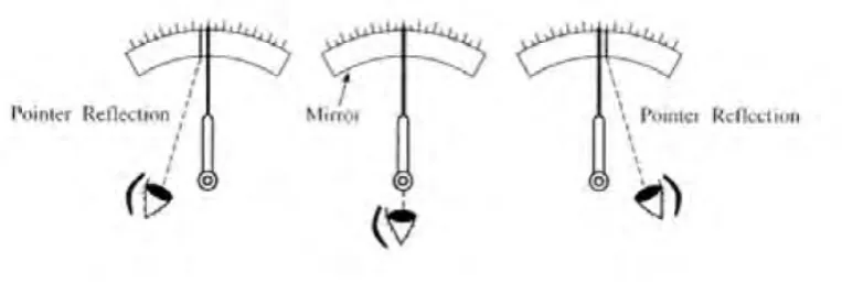
[image:12.595.130.512.288.417.2]The ideas for this project is come out after doing a research on the accuracy of the inspection that been done by the human and compared with intelligent visual inspection system. The most difficult task for inspection system is inspecting by visual appearance of the object. As human measured the object by using contact method measurement, it might has consist with human error. This is exactly cause the inaccurate reading. By this project, the theoretical of dimensional measurement would be applied into the vision of intelligent inspection system.
Figure 1.1: Human eye error of reading measurement
1.3 Objectives of The Study
1. To determine the theoretical dimensional measurement by vision system.
3
1.4 Scope of The Study
The scopes of this project are to study theoretical dimensional measurement acquired by the vision system. The captured image then will be analyzed by software and finally will generated the object dimensional measurement. The images are captured by sing Charge Couple Device (CCD) camera from JAI® Company model. This camera is connected with Matlab Software to convert the images to the algorithms. The algorithms that get from the captured images will convert the pixel to the millimeter measurement, and finally dimensional measurement will be generated. Other than that, the scopes of this project are the theoretical dimensional measurement acquired by the vision system in screw industry.
1.5 Project Outline
4
CHAPTER 2
LITERATURE REVIEW
1. 2.1 Introduction
5 2.1.1 Important of dimensional measurement
Dimensional measurement is how we know and quantify the size and shape of things. It involves lengths and angles as well as geometrical properties such as flatness and straightness. Dimensional measurement is of fundamental importance for interchangeability and global trade. It is how we ensure that things will fit together. Without global length standards as the basis for standardized parts globalized industry would not be possible.
Dimensional Measurement allows interchangeability and global trade by ensuring things fit together
Dimensional measurement is also key to ensuring products perform as intended. For example the strength of structures is calculated using measurements such as the thickness of a flange or the span of a beam. Uncertainty in these measurements therefore increases uncertainty in the strength. This is very important for safety critical structures, for example an aircraft wing or a bridge. Another example of how measurements affect product performance is aerodynamics. If the body of a car or wing of an aircraft does not closely match the aerodynamic form which has been optimized in wind tunnel testing then the performance will not be as expected.
Dimensional Measurement determines our confidence in the strength and aerodynamic performance of products
6 magnet positioning over 10’s of kilometres. In astronomy dimensional measurement is also critical with the most accurate optical telescopes requiring very large mirrors with sub-micron accuracy. The science of dimensional measurement is dimensional metrology, these terms are often used interchangeably.
Recently, there are various types of theoretical of dimensional measurement. These type of product appeared with much kind of features and character, but with the same task. This part will discuss about theoretical of dimensional measurement that existed, their specification and how it calculated.
2.2 Theoretical of dimensional measurement by vision (eye)
Scientists studying a forest ecosystem over a long period of time may record measurements of trees for a number of variables, including each tree's diameter at breast height, height of the lowest living branch, canopy cover, etc. One aspect of a tree's growth that can be hard to measure is tree height. Forest researchers sometimes use a piece of equipment consisting of telescoping components, which are extended until the tip reaches the same height as the tree top (this requires a second researcher standing at a distance from the tree to determine when the tip is at the correct height). This method can be cumbersome, as the equipment is bulky and the measurements require two people.
Methods: Trigonometry is a branch of mathematics dealing with measurements of
the angles and sides of triangles, and functions based on these measurements. The three basic trigonometric functions that we are concerned with here (sine,
7 are the trigonometric functions of an angle, theta, such that
where (theta) is the angle of interest, "opp" is the length of the side of the triangle opposite (y), "hyp" is the length of the hypotenuse (z), and "adj" is the length of the
[image:17.595.133.423.318.606.2]side adjacent to the angle (x), as illustrated on the triangle below.
Figure 2.1: Trigonometry Measurement
8 or y2 + x2 = z2). For the triangle below, the side opposite is three units in length, and
the side adjacent to is 1.5 units in length.
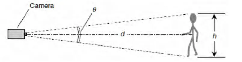
[image:18.595.126.530.276.560.2]The drawing below shows a forester measuring a tree's height using trigonometry. Assuming that the tree is at a right angle to the plane on which the forester is standing, the base of the tree, the top of the tree, and the forester form the vertices (or corners) of a right triangle. The forester measures his or her distance from the base of the tree, and then uses a clinometer (a small instrument that measures inclination, or angle of elevation) to look at the top of the tree and determine the height.
Figure 2.2: Human eye error of reading measurement
9 Object Distance and Size Measurement Up to this point, all the processing was done in parallel on two images captured from the two cameras. Distance measurement and size calculation use the information extracted from the object of interest information on both images. Distance measurement. Distance measurement is done by using the using the disparity value of the object of interest in the two image, d in pixel. Since the camera is aligned in parallel, we can simply take the pixel difference between the two width center lines of the object of interest as the disparity. The distance, D of the object can be calculated using the following equation:
D = βd^-1
Where is a fixed parameter given by:
β= b f
where b is the separation distance between two cameras and f is focal length of the cameras.
2.4 Size Measurement
For size measurement, which consists of width and height, the calculations are done by using the disparity value in pixel, d and the pixel value of the width, w and the height, h of the blob. The calculations of actual object width, W and height, H are done using the relationship of between width per pixel, ᵞw and height per pixel, ᵞh to the disparity. From our experiment we found that width per pixel and the height per
pixel value of an object are linear and inversely proportional to its disparity. The equation for the width, W and height, H calculation is as the following:
10 H =ᵞh h
ᵞw and ᵞh are obtained from a linear equation of a graph of ᵞw and ᵞh against d as the following:
ᵞw = mw d + cw ᵞh = mh d + ch
where m is the gradient of the plotted graph and c is the value of ᵞat d = 0. The graph of ᵞw and ᵞh against d are plotted by experimenting on several samples with known actual width and height. For different disparity value (varied by changing the distance of the object), the value of the ᵞw and ᵞh is calculated and plotted.
2.5 Object Identification
Different objects can be distinguished from each other depending on their sizes. For example a car will have a different width compared to a pedestrian. For our system object is identified according to their height, h to width, w ratio and the height-width, h w product (blob area). A database is utilized to store the information and the associated label of known objects. If an object with matching information is found, the object will be identified. When a new object with no matching height to width ratio and height-width product in found, a new label will be instantiated for that object in the database.
2.6 Dimensional Measurement of Vision System in Industrial
11
dimensions and are related to the first of the four types of inspection defined namely the inspection of dimensional quality.
[image:21.595.120.523.405.509.2]Various industries are involved in the development of vision systems for automated measurement of dimensional quality. In packaging industry, the tasks vary from measurements of the fill level in bottles, to sell by date inspection and to airbag canister inspection (e.g. online gauging systems that measure height, concentricity and diameter of airbag canisters). A vision-guided system for the automated supply of packaging machines with paper and foil material is presented. The system enables the manipulator to locate the proper bobbin, depalletize it and transfer it to the requesting machine. A similar application is addressed in a vision system is used to determine the correct position of pallets and recognize the arrangement pattern of sacks on the pallets. The system enables a robot mechanism to grasp the sacks and pass them along a rotating cutting disk.
Figure 2.3: Camera analyze height measurement
2.7Inspection applications
12 3.1 Introduction
The design of any research project requires considerable attention to the research methods and the proposed data analysis. Within this section, it to provide some information about how to produce a research design for a study. It is a basic overview of the research methods portion of a research proposal and then some data analysis templates for different types of designs. It not promised to be success but it will provide a head start. There is a structured plan in completed this methodology which consist finding appropriate title for the project, research through journal and article, planning on a project design and parts that will be need, hardware and software implementation to the project, test run the project, troubleshooting the problem occur and report writing. In any project, an organization which elaborates the process to complete the project is a must. In order for that, a complete flow chart is created involving the steps to accomplish this project from start to end. Apart from that, it is also necessary to understand on the tools which is software tools that are used in this project before to start on it.
2.0 Methodology
The purpose of project methodology is to allow for controlling the entire
management process through effective decision making and problem solving, while ensuring the success of specific processes, approaches, techniques, methods and technologies. Typically, a methodology provides a skeleton for describing every step in depth, so that a
13
project manager will know what to do in order to deliver and implement the work according to the schedule and specification.This project is present to apply theoretical dimensional measurement by vision system and get the statistical computing, graphics and data by using MatLab software. This project will focus on suitable theoretical dimensional measurement to be apply by vision system.
[image:23.595.119.533.289.463.2]The flowchart is for writing on a report; that is planning for a project, implementing the hardware and software that need to be on the project and analyzing the overall of the project which conforming that the project is a success. Also included is the qualitative method on finding the information concerning to a project.
14 3.3 Problem Solving Method
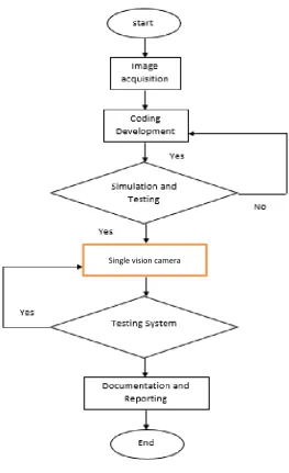
Figure 3.2: Project flowchart
The figure above shows the flowchart throughout the project process is being held. The first step is a find an idea of a project and planning the design of project idea and an estimated time to manage this is about a day. Next, researching about a related project think of the possibility to whim a project idea. An estimated time to manage this part is about a month. Then, design a schematic whether using a software simulation or sketch it, also what is a software to be used in the schematic design. After satisfied with all of the designing software, assemble them all and implement the software into the MATLAB software and do