UNIVERSITI TEKNIKAL MALAYSIA MELAKA
FINITE ELEMENT OF HUMAN SPINE
CAD MODEL ANALYSIS
This report submitted in accordance with requirement of the Universiti Teknikal Malaysia Melaka (UTeM) for the Bachelor of Manufacturing Engineering
(Manufacturing Design) with Honours.
by
MOHAMAD SHAHRUL EFFENDY BIN KOSNAN
UTeM Library (Pind.1/2005)
UNIVERSITI TEKNIKAL MALAYSIA MELAKA (UTeM)
BORANG PENGESAHAN STATUS TESIS*
JUDUL: FINITE ELEMENT OF HUMAN SPINE CAD MODEL ANALYSIS
SESI PENGAJIAN: 2009/2010
Saya MOHAMAD SHAHRUL EFFENDY BIN KOSNAN
mengaku membenarkan tesis (PSM/Sarjana/Doktor Falsafah) ini disimpan di Perpustakaan Universiti Teknikal Malaysia Melaka (UTeM) dengan syarat-syarat kegunaan seperti berikut:
1. Tesis adalah hak milik Universiti Teknikal Malaysia Melaka.
2. Perpustakaan Universiti Teknikal Malaysia Melaka dibenarkan membuat salinan untuk tujuan pengajian sahaja.
3. Perpustakaan dibenarkan membuat salinan tesis ini sebagai bahan pertukaran antara institusi pengajian tinggi.
4. **Sila tandakan (√)
SULIT
TERHAD
TIDAK TERHAD
(Mengandungi maklumat yang berdarjah keselamatan atau kepentingan Malaysia yang termaktub di dalam AKTA RAHSIA RASMI 1972)
(Mengandungi maklumat TERHAD yang telah ditentukan oleh organisasi/badan di mana penyelidikan dijalankan)
(TANDATANGAN PENULIS)
Alamat Tetap: No 16, JLN ORKID 6, TMN ORKID, 86000 KLUANG, JOHOR
Tarikh: 18 MAY 2010
Disahkan oleh:
(TANDATANGAN PENYELIA)
Cop Rasmi:
DECLARATION
I hereby declare that this report entitled FINITE ELEMENT OF HUMAN SPINE CAD MODEL ANALYSIS is the result of my own research except as cited in the references.
Signature :
Author’s Name : MOHAMAD SHAHRUL EFFENDY BIN KOSNAN
APPROVAL
This report is submitted to the Faculty of Manufacturing Engineering of UTeM as a partial fulfillment of the requirements for the degree of Bachelor of Manufacturing Engineering (Manufacturing Design) with Honours. The members of the supervisory committee is as follow
………….………. En. Abd. Halim Hakim b. Abd. Aziz
i
ABSTRACT
In industry, there are many major industrial accidents. One of these is lower back pain. These injuries are responsible for the bulk of compensation money spent. Statistically problem in lower back pain of workers will affect the productivity of work. The activities such as lifting, pulling, pushing and sitting in the long period of time will cause low back pain problem. In industrial, this can be avoided by designing proper ergonomic workplace. There is a need to devise way to reduce the incidence and prevalence of back pain disorders, especially in the workplace. A proper investigation is done to a spine regarding this problem. Usually there is two types of experiment involve in analyzing the spine which are:
1. Using vitro models (cadaveric and mathematical)
2. Using investigation of software
In this thesis, Finite Element Method used CAD model to be analyzed.
Finite Element is the best method can be used to visualize stress distribution on the lumbar spine. The finite element method of numerical analysis has enabled researchers to solve many problems. Continuous advancements in numerical technique as well as computer technology have made the finite element method a versatile tool for biomechanics application. In this paper, the Finite Element Analysis (FEA) is done in Patran Nastran software. The lumbar spine model is generated in Solidworks software so that it eased the exporting procedure to send the model of lumbar spine. From the FEA, it can conclude that
the end plate at 5th lumbar is experiencing maximum stress. 4th and 5th lumbar also affected
ii
ABSTRAK
Terdapat banyak kemalangan utama dalam sektor perindustrian. Salah satu daripadanya ialah kesakitan di bahagian pinggang. Kecederaan ini memerlukan kos perbelanjaan yg tinggi untuk pulih. Secara statistiknya masalah kesakitan di bahagian pinggang pekerja-pekerja akan menjejaskan produktiviti kerja seharian mereka. Aktiviti-aktiviti itu seperti mengangkat, menarik, menolak dan duduk dalam tempoh yang panjang itu akan menyebabkan masalah di bahagian pinggang berlaku. Perkara ini boleh dielak dengan menyediakan tempat kerja yang ergonomi dan selesa. Terdapat satu keperluan untuk manyelesaikan masalah bagi mengurangkan kesakitan di bahagian pinggang, terutama sekali di tempat kerja. Terdapat 2 jenis analisa yang selalu digunakan, antaranya :
1. Menggunakan vitro pelbagai model (kadaver dan matematik)
2. Menggunakan analisa perisian komputer.
Dalam tesis ini, Kaedah Unsur Terhingga digunakan model CAD untuk dianalisa. Elemen terhad adalah kaedah terbaik untuk mendapatkan taburan tegasan pada spina lumbar. Kaedah unsur terhingga analisis berangka itu telah berupaya untuk menanggani pelbagai masalah. Kemajuan selanjar dalam teknik berangka serta teknologi komputer telah membuat kaedah unsur terhingga itu satu alat serba guna untuk kemajuan biomekanik. Dalam tesis ini, FEA yang digunakan adalah perisian Patran Nastran. Spina lumbar model dihasilkan dalam perisian Solidwork supaya ia mudah menghantar model spina lumbar untuk dianalisa.
Daripada Analisis Unsur Terhingga, dapatlah disimpulkan bahawa plat hujung 5th lumbar
mengalami tekanan maksimum. Plat hujung 4th dan 5th lumbar juga terjejas oleh beban yang
iii
DEDICATION
iv
ACKNOWLEDGEMENTS
I wish to acknowledge and express my gratitude and appreciation to (i) my supervisor, Mr. Abd. Halim Hakim b. Abd. Aziz of his supervision, encouragement, suggestion and assistance through the research; (ii) my parents, Mr. Kosnan B. Berow and Siti Alijah Bte Md. Dekan whose constant encouragement, faith and confidence besides continuously moral support; (iii) Mr. Tajul Ariffin B. Abdullah for his idea and full encouragement.
In addition, I would also like to thank my friends Nur Farizan, Eezafri, Syafirul Ikmar, Azrin, Rabiatul Adibah and Mohamad Nur because taking a lot of their time to help and giving ideas with my research.
v
TABLE OF CONTENTS
Abstract.. ... i
Dedication ... iii
Acknowledgement ... ....iv
Table of Contents ... ....v
List of Figures ... ix
List of Tables ... ....xi
List of Abbreviations, Symbols and Specialized Nomenclature ... ....xii
CHAPTER 1 INTRODUCTION ... 1
1.1 Project Background ... 1
1.2 Problem Statement ... 3
1.3 Objectives ... ....3
1.4 Scope of Project ... ....3
CHAPTER 2 LITERATURE REVIEW ... 5
2.1 Introduction of Human Spine ... 5
2.1.1 Anatomy and Function ... 5
2.1.2 Section of the Spine... 7
2.1.3 Regional Characteristic of Vertebrae ... 8
2.2 Spinal Mobility – Condition and Instrument ... 11
2.2.1 Movement of the Spine ... 11
2.2.2 Load on the Spine ... 13
2.2.3 Spinal Injuries ... 13
2.2.4 Spinal Treatment ... 15
2.3 Introduction of Computer Aided Design (CAD) ... 17
2.3.1 Element of CAD System ... 17
2.3.2 CAD software (Solidworks) ... 18
vi
2.3.2.2 Component Based ... 19
2.3.3 Terminology ... 19
2.3.4 3D Computer Graphics... 20
2.4 Introduction of Finite Element Analysis (FEA) ... 21
2.4.2 History of the FEA ... 21
2.4.3 Terminology Used in FEA ... 23
2.4.3.1 Processing ... 23
2.4.3.2 Analysis (Computation of Solution) ... 24
2.4.3.3 Visualization ... 24
2.4.4 Patran Nastran Software ... 24
2.4.5 How does Finite Element Analysis Work? ... 26
2.4.6 Material Properties ... 27
2.4.7 Application of FEA to the Mechanical Engineering Industry... 28
2.4.8 The Advantage of FEA ... 28
2.5 Solid Modeling and the Human Body ... 29
2.6 Biomechanics in Human Spine... 31
2.6.1 Definition of Biomechanics ... 31
2.6.2 External versus Internal Loading ... 32
2.6.3 Lever System in the Body ... 32
2.6.4 Biomechanics of the Lumbar Spine ... 33
2.6.5 Kinetics... 33
2.6.6 Static Loads on the Lumbar Spine during Lifting ... 33
CHAPTER 3 METHODOLOGY ... 35
3.1 Introduction ... 35
3.2 Flow chart ... 36
3.3 Phase of Methodology ... 37
3.3.1 Planning Phase ... 37
3.3.2 Implementation Phase ... 38
3.3.3 Analyze phase ... 38
3.3.4 Result and Discussion phase ... 38
3.3.5 Preparation of Final Report and Presentation ... 38
vii
3.5 Gantt Chart PSM II ... 41
CHAPTER 4 IMPLEMENTATION ... 42
4.1 Introduction ... 42
4.2 System Requirement ... 42
4.3 Steps for Create 3D Model of Lumbar Spine ... 43
4.4 Process to Generate Lumbar Spine Manually ... 43
4.5 Process to making CAD model Lumbar Spine ... 44
CHAPTER 5 ANALYSIS ... 50
5.1 Introduction ... 50
5.2 Calculation of Internal Loads on The Spine with Object is Being Carried or Lifted... 50
5.2.1 Lifted Object with 35° Back Inclined ... 51
5.2.2 Carried Object with Static Posture ... 53
5.3 Internal Load for each Weight ... 54
5.4 Process to Analyze using Finite Element Analysis (FEA) Software ... 55
5.5 System Requirement ... 55
CHAPTER 6 RESULT AND DISCUSSION ... 61
6.1 Introduction ... 61
6.2 Result in Table ... 63
6.3 Result in Figure ... 66
6.3.1 Result for Von Mises Stress Static Posture ... 66
6.3.2 Result for Von Mises Stress 35° Back Inclined ... 78
6.3.3 Result for Displacement Static Posture ... .71
6.3.4 Result for Displacement 35° Back Inclined ... 73
6.4 Discussion ... 76
6.4.1 Von Mises Stress Comparison ... 76
6.4.2 Displacement Comparison ... 78
viii
7.1 Conclusion ... 83
7.2 Recommendation ... 84
7.2.1 Lifting ... 84
7.2.2 Pushing and Pulling ... 85
7.2.3 Posture ... 86
REFEERENCES ... 87
APPENDICES
Appendix A : Proper Lifting Technique and Back Brace Use Appendix B : Manual Lifting with Good Practice
ix
LIST OF FIGURES
Figure 1.1 : Human Spine with all view …. ... 4
Figure 2.1 : Transverse, Frontal and Sagital Plane ... 6
Figure 2.2 : Segments of the Spine, Medial View and Frontal View .. ………7
Figure 2.3 : Atlas ... 9
Figure 2.4 : Axis ... 9
Figure 2.5 : Cervical vertebra ... 9
Figure 2.6 : Thoracic vertebrae ... 10
Figure 2.7: Lumbar Vertebra ... 10
Figure 2.8: Disc Herniation ... 14
Figure 2.9: Terminology of Solidworks ... 20
Figure 3.1: Flow Chart of Final Year Project ... 36
Figure 4.1 : High of Cortical Bone ... 44
Figure 4.2 : Length and Width of Cortical Bone... 44
Figure 4.3a : Final CAD lumbar spine (isometric view) ... 48
Figure 4.3b : Final CAD lumbar spine (side view) ... 49
Figure 5.1 : Calculation 65% of the weight of body ... 51
Figure 5.2 : Illustration of 35° when lifting the load ... 52
Figure 5.3 : The formula of moment equilibrium equation... 52
Figure 5.4 : Free body diagram when person carry load in erect posture ... 53
Figure 5.5 : illustration when person carry load in erect posture (static) ... 53
x
Figure 6.1a : Mesh solid with side view ... 62
Figure 6.1b : Isometric mesh solid view ... 62
Figure 6.2a : 20 kg stress static posture ... 66
Figure 6.2b : 40kg stress static posture ... 66
Figure 6.2c : 60 kg stress static posture ... 67
Figure 6.2d : 80 kg stress static posture ... 67
Figure 6.2e : 100 kg stress static posture ... 68
Figure 6.3a : 20kg stress 35° back inclined………... 68
Figure 6.3b : 40kg stress 35° back inclined ... 69
Figure 6.3c : 60kg stress 35° back inclined ... 69
Figure 6.3d : 80kg stress 35° back inclined ... 70
Figure 6.3e : 100kg stress 35° back inclined ... 70
Figure 6.4a : 20kg displacement static posture ... 71
Figure 6.4b : 40kg displacement static posture ... 71
Figure 6.4c : 60kg displacement static posture ... 72
Figure 6.4d : 80kg displacement static posture ... 72
Figure 6.4e : 100kg displacement static posture ... 73
Figure 6.5a : 20kg displacement 35° back inclined ... 73
Figure 6.5b : 40kg displacement 35° back inclined ... 74
Figure 6.5c : 60kg displacement 35° back inclined ... 74
Figure 6.5d : 80kg displacement 35° back inclined ... 75
Figure 6.5e : 100kg displacement 35° back inclined ... 75
Figure 6.6 : Graph for Von Mises Stress vs. Load when standing erect in static posture and carrying object ... 76
Figure 6.7 : Graph for Von Mises Stress vs. Load when lifting object with 35° back inclined ... 77
Figure 6.8 : Comparison between static posture and 35° back inclined ... 78
Figure 6.9 : 35° inclined (displacement) magnitude ... 79
Figure 6.10 : Displacement (magnitude) for 35° back declined ... 80
xi
LIST OF TABLE
Table 2.1 : Representative degree of rotation at the vertebral junctions of the spine 12
Table 2.2 : ASIA (American Spinal Injury Association) Impairment Scale ... 16
Table 4.1 : Dimension of Lumbar Spine ... 43
Table 4.2 : Steps to making CAD modeling of Lumbar spine ... 45
Table 5.1 : Internal load calculated for each weight ... 54
Table 5.2 : Process to making analysis using Patran Nastran software ... 56
Table 6.1a : Von Mises Stress for static posture ... 63
Table 6.1b : Von Mises Stress for 35° back inclined ... 63
Table 6.2a : Displacement (magnitude) for static posture ... 64
Table 6.2b : Displacement 35° back inclined for displacement (magnitude) ... 64
Table 6.3 : Von Mises Stress for static posture ... 76
Table 6.4 : Von Mises Stress for 35° back inclined ... 77
Table 6.5 : Displacement (magnitude) for static posture ... 78
xii
LIST OF ABBREVIATIONS, SYMBOLS AND
SPECIALIZED NOMENCLATURE
3D - Three Dimension
ASIA - American Spinal Injury Association
CAD - Computer Aided Design
CAE - Computer Aided Engineering
CT - Computed Tomography
FEA - Finite Element Analysis
kg - Kilograms
MRI - Magnetic Resonance Imaging
N - Newton
1
CHAPTER 1
INTRODUCTION
1.1 Project Background
2
The advantages of using FEA are complex geometry and boundary conditions can be modeled, inhomogeneous and non-linear materials simulated, parametric studies isolating the effect of one or more variables can be performed, and delineating the stress distributions in the various components of the biological structure can be accomplished. This information may serve as a basis to evaluate the response of the normal structure and the effects of degeneration or surgical interventions. In many structural systems, however, there is a great deal of uncertainty associated with the environment in which the structure is required to function. This variability or uncertainty has a direct effect on the structural response of the system. Biological systems are an archetype such as uncertainty and variability exist in the physical and mechanical properties and geometry of the bone, ligaments, cartilage, as well as uncertainty in joint and muscle loads.
3
1.2 Problem Statement
In industry, there are many major industrial accidents. One of these is lower back pain. These injuries are responsible for the bulk of compensation money spent. Statistically problem in lower back pain of worker will affect the productivity of work. The activities such as lifting, pushing and sitting in the long period of time will cause low back pain. In this thesis, Finite Element method use CAD model to be analyzed. Finite element is the best method that can be used to visualize stress distribution on lumbar spine. So we will know as much as which lumbar spine capable to holding heavy load.
1.3 Objectives
The aims of this thesis are:
1. To construct 3D computer model of lumbar spine by using CAD software (Solidworks 2009).
2. To analyze 3D finite element model by using CAE software (Patran Nastran).
3. To investigation the Von Mises stress and displacement when erect posture and 35° back inclined in lumbar spine.
1.4 Scope of Project
This project focus on lumbar spine with is 1st lumbar till 5th lumbar. The purpose of
4
Figure 1.1 : Human Spine with all view
5
CHAPTER 2
LITERATURE REVIEW
2.1 Introduction of Human Spine
The spine is a complex and functionally significant segment of the human body. It protects the central nerve, which runs through an opening in each of the interconnecting vertebrae. It also serves as the axial support for the skeleton and provides for the flexibility and bending of the back. There many function of human spine and the each part of the spine have their own characteristic. (McIntosh 1998). The function and characteristic of human spine will discuss in this chapter.
2.1.1 Anatomy and Function
The mature human vertebral column usually consists of 24 pre-sacral vertebrae, the remainder being arranged into five fused sacral vertebrae and three to four coccygeal vertebrae. In addition to the bony structures there are 23 intervertebral discs between each vertebra and associated ligaments, muscles, and tendons. This thesis focuses on the osseous or bony spine which will be discussed in detail. (Douglas P. Breglia, 2006)
6
[image:22.595.222.418.268.587.2]anatomical position. The planes are referred to as the transverse or horizontal plane, the frontal or coronal plane, and themadian sagittal or median plane as. The transverse plane divides the body into upper and lower or superior and inferior parts. The median plane divides the body into left and right portions. The body has a single median plane and many sagittal planes that are parallel to the median plane. The anatomical term medial means closer to the median plane, while lateral means farther from the median plane. Finally the coronal or frontal plane divides the body in to front and rear portions, where anterior is towards the front or face and posterior is toward the rear or back.
Figure 2.1 : Transverse, Frontal and Sagital Plane
(Highschoolanatomy.org)
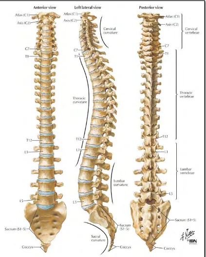
7 2.1.2 Section of the Spine
[image:23.595.187.450.158.467.2]The spine is divided into five sections: the cervical, thoracic, lumbar, sacral and coccygeal spine as seen in figure below.
Figure 2.2 : Segments of the Spine, Medial View and Frontal View
(Atlas of Anatomy)
The cervical spine is the most superior section, which means it is closest to the head, and the coccygeal spine is the most inferior, or closet to the feet. The cervical section of the spine is comprised of the seven neck bone. Next is the thoracic spine which is the 12 bones of the chest to which the ribs attach. Then the lumbar spine made of five bones in the lower back. Next the sacral spine which is a single bone made from five fused sacral segments attached to the pelvis, and finally the coccygeal spine.
8
convex toward the posterior. The thoracic spine has a kyphosis, or a curve convex towards the anterior of the body.
This project focuses on the vertebrae that have very similar geometry. This include the lumbar spine because of extremely load.
2.1.3 Regional Characteristic of Vertebrae
The vertebrae in each region of the spine are characterized by differences in elements and geometry. The following are some of the characteristics that distinguish one vertebra and one region from another. (Jenna Bowling, 1998)
Cervical vertebrae: The cervical vertebrae are the first (upper) seven in the