Abstract: This paper mainly presents fuzzy current controller depending on speed estimator of MRAS with field oriented controlled induction motor drives. This paper consists of three main techniques used for configurations of MRAS speed estimators that is Rotor Flux, Back - EMF and Instantaneous Reactive power. The MRAS estimators are then included into a direct field oriented controller and also a comparison is done between PI and fuzzy current controllers completely tested on MATLAB/SIMULINK. The resulting controller achieves an acceptable level of execution over wide range of good operating conditions.
Keywords: Fuzzy Logic Controller (FLC), Field Oriented Control (FOC), Model Reference Adaptive System (MRAS), Sensor Less Speed Control.
I. INTRODUCTION
Now days, the induction motor drives (IMDs) with adaptable speed drives (ASDs) are very important as its high discharge, rugged design and mostly operates in industries such as; battery operated frictions and composite motor vehicles, switch engine propulsion, scheme of scalar control which gives better invariant response, however it gives low active response. The methods of both steady stateand also transient state give good satisfactory responses [1].The IMD of DC motor performs like separately excited motor known as vector control or the field oriented control (FOC) and it was first suggested earlier in 1970’s [2] by Hassle (Indirect FOC) and F.Blaschke (Direct FOC).
In the method of FOC having good characteristics and it suffers from some limitations, which are essential of some synchronized changes, controller currents, easily effected by parameter variations these are the disadvantages of FOC method [3]techniques of reduced new control strategy that is IFOC method, in early 1980’s which are presented by Isao Takahashi and Toshihiko Noguchi. In the direct field oriented control of an induction motor drive is very essential for the angular position of rotating shaft information; rotating shaft is attainable by considering the sensors of speed (i.e. speed encoding) else from the IMD parameters to estimator observer by the use of currents and voltage signaling. The main aim of speed encoder is corresponding with some
Revised Manuscript Received on August 05, 2019.
C.Lavanya*, Electrical and Electronics Engineering, JNTU Ananthapur, INDIA. Email: [email protected]
S.SRIDHAR, Electrical and Electronics Engineering,JNTU Ananthapur,
disadvantages are, essential of shaft extension, automatic vibrancies of the machine drive is decreased, the operating motor accuracy is decreased and does not suitable for the uncertain atmosphere changes, and high expensive. These disadvantages leads to speed sensor less of indirect field oriented controlled IMD having good features above typical DFOC control. Speed sensor less drive, which does not have any sufficient space for the sensor speed to the essence of the nature which do not allow for any extra speed sensors of rotor.
Over the past decades, many schemes are introduced for the rotor speed estimation in the sensor less vector control of IMDs [4-10]. Some of the methods are (i) method of signal injection [4], (ii) method of state observers [5], (iii) method based on model configurations [6]. Signal injection method tolerates from difficulty calculations and essential for the outer equipments for the signal injection method. According to all the schemes of MRAS [7-10] speed estimators is usual working procedure because of their good characteristics, merely contrasting the scheme of injecting signal. Back-emf [4], rotor-flux [7], reactive power [5] and active power [10] are the most desired methods of MRAS. The method of back emf which gives good execution when speeds are high, although speed estimation is more complex at initial condition and it possess less speedy and hardly empathetic to motor constant. Hence, to prevent these disadvantages, rotor flux of MRAS method is most popular and it was first proposed by C Schnauzer in [11].
II. SIXPHASEINDUCTIONMACHINE MODELLING
Six phase induction motor (6PIM) of dual three phase having compatible arrangement, and it mainly focuses between five and six phase multi-phase induction machine. The induction machine is having of two sets of three phase loops displaced geographically by 30°(in asymmetrical mode) or 60°(in symmetrical mode) electrically with one or two typical objective points. The asymmetrical configurations are having good torque performance compared to symmetrical one. The two typical objective points are maximizes the use of dc-link of 6PIM and it deflects the zero sequence currents of degree freedoms. The two isolated neutral point having healthy mode operations, while fault tolerant applications are for single isolated neutral point.
Sensor less Speed Estimation of an Foc
Induction Motor Drive using Mras Speed
Controller and Fuzzy Current Controller
A. SIX PHASE IM MODELLING
The stationary voltage equations of stator and rotor are expressed as
= + (1) 0= + − (2)
The equations of flux linkages are as follows:
= + (3)
= + (4)
Where
=
+
,
=
+
,
=
+
,
=
+
,
=
+
Are the currents of stator and rotor
Are the flux linkages of stator and rotor
Are the resistances of stator and rotor
Are the inductances of magnetizing, rotor and stator, imaginary unit is represented by ‘j’, and operating derivative is denoted by p.
The 6PIM of electromagnetic torque is calculated as follows:
= 3 (5)
The number of pole pairs is represented by ‘p’ and cross product represents by‘ .
The field oriented indirect controller (IFOC) IMD schematic diagram is represented in Fig.1.below, is a method of IFOC [13] which provides a quick occurring line torque as well as stator flux control because of its increased choice of switching vector voltages of both the flux and torques of stator comparisons concurrently in between with the modulating of current controllers. The successive voltage of vectors is related to the machine drives depending on the selected errors in torque and flux of stator incidentally. The
IFOC technique for the drive evolves the
electromagnetic torque, linkages of both the flux and the stator flux linkage of angular position of vector spaces are determined in the form of d-axis and q-axis module which are given below are:
^ (6)
=
⁻ (
(7)
=
tan
−1(
) (8)
*dt
= ᶴ (
III. MRASBASEDPIANDFUZZYCONTROLLER OFINDUCTIONMOTOR
The proposed method of MRAS which are based on PI current controller and Fuzzy current controller approach. MRAS methods are one of the most popular methods which are used for rotor speed estimation to detect the sensor speed at different speeds. Overall the control of MRAS speed estimation [11], [14]. The stability theorems of non linearity are Lyapunov’s stability or Popov’s stability schemes of an adaptation law used the design of system is relatively stable. In Significance of identifying the vigorous response of the combining methods which do not produced by the stability theorem of nonlinearity, the adaptation law of stability additionally cannot be undertaken for lessspeed manner of regeneration. In order to conduct this type of researches, this is essential to adjust induction machine of six phase equations throughout the control point and it transfers the function of the MRAS, which is presented in this paper.
A. Adaptation Law design
State-space equations are considered in general form is as follows:
= + (9) y = (10)
The 6PIM of state space model in the z1, z2 Subspace can be reduced from (11) and (12) equations follow:
P[ =
[ ]=
[
(11)
Observer state equations can be rewrite as below
^ = ^ ^ + (12)
^ = ^ (13)
The “^”indicates that the sign of approximate value of MRAS. The leakage inductance of stator is kept continuous, the estimation controllers are deduced, when errors are possible, and variations are to be neglected. The error is based on correcting term G(x∆ ^) mentioned, which eliminates in the equation (11), the observer gain matrix is denoted by G, which is a regular convention of estimators of MRAS [16]. The type of observer is known as “natural observer” [20] researched by some analysis. The state variable error matrix is followed by:
e = x- ^ = [ 1 − ^ 2 2 − ^ 1 ]T = [ 1 2] (14)
The error matrix of time derivative is estimated by (11), (13), and (14) as
= – ^ = − ∆ ^ (15)
where A is given as
∆ - A=
The PI controllers are used in conventional systems. PI controller is a combination of proportional and integral controllers with the objective of achieving the desired response with minimum and maximum time of precision. In this PI controller used for estimation, so that it is very difficult to modify. In some cases of the final response which is not achieved, this is a time taking and low processing. Due to this drawback, to overcome this problem fuzzy logic controller came into existence. Fuzzy current controllers of 6PIM are very excellent features controllers over PI controllers; they achieve the final response and stable conditions without any delay.
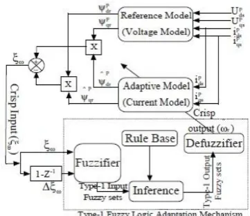
Fig. 1. The Basic schematic block of MRAS.
IV. FUZZYLOGICCONTROLLERADAPTATION
MECHANISMANDIMPLEMENTATIONOFMRAS
SPEEDESTIMATION
In recent years, Fuzzy logic modeling [15],[19] replaced many conventional techniques successfully in many areas with respect to MRAS speed estimation[18]. In complex problem solving it is easy to derive control rules by mathematically modeling the process. Mamdani technique is the most commonly used fuzzy inference system techniques and other techniques are Sugeno, Takagi and Kang.
A. Adaptation Mechanism Of Fuzzylogic Controller.
Fuzzy logic controller is the discrete, adjustable governing process, which tends to rugged implementation extending unexpected speed changes and also disturbances in loads. FLC manages complex of non linearity system which is having degrees of unreliability, it do not requires numerical simulation and inconsistent continual parameter obtain and to create PI controller is capable for induction machine drive [13]. Rotor-flux MRAS based FLC mechanism adaptation schematic diagram is as shown in Fig.2. Below.
a. Rule Base design of fuzzy
FLC shifts a semantic control technique to mechanical power technique, rule base fuzzy designs is knowledgeable. The FLC rule base model is necessary for explaining rules that can associated with the both input and output type variable premises [8,13]. Adaptation mechanism of advanced fuzzy controller aims to evaluate speed of rotor is in control state of induction motor drive.Reference model (RM) and the adjustable model (AM) of both signal errors are used in the adaptation mechanism of fuzzy logic control for the estimation of speed in rotor.
Fig. 3. The normalized triangular M.F’s of fuzzy input, fuzzy output variables are: (a) change in speed
[image:3.595.66.266.207.320.2]error, (b) torque reference.
[image:3.595.319.538.372.532.2] [image:3.595.83.264.610.766.2]V. SIMULATIONRESULTS
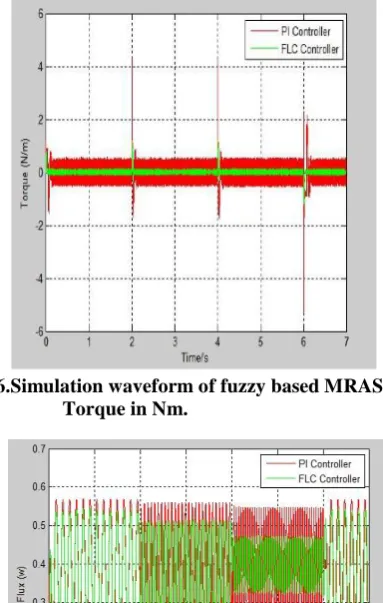
[image:4.595.329.521.53.355.2]This paper simulates that the results taken for the evaluation of MRAS scheme performance to the FLC which is analyzed by a mathematical simulation. The MATLAB/Simulink design is verified in the system [3] individually, with some of the equivalent research papers [7], [8] and [11],[14] with the 10 kHz frequency samples is kept constant below, the no load and the change in command speed and step change of open loop simulation results are mentioned below in Fig. 5, the flux in stator value is kept up to 0.4 Wb and estimation process is activated when t=1s. Clearly, known that the speed estimation is intersects at real value of its divergent with incorrect initial conditions irrespective of the change in speed. Simulation results below the step change of torque at load condition of open loop around 2 Nm and the rated speed are of 2700 rpm and synchronous speed is around 1500 rpm which is mentioned below in Fig. 6,also seen that the stator flux.Fig.5. Shows that simulation modeling of Speed in RPM.
[image:4.595.325.524.248.427.2]Fig. 4. The proposed fuzzy logic controller of 6PIM MATLAB/SIMULINK Model.
[image:4.595.51.254.291.445.2]Fig 5.Simulation comparison waveform of fuzzy based MRAS speed (rpm).
[image:4.595.64.269.500.667.2]Fig 6.Simulation waveform of fuzzy based MRAS Torque in Nm.
Fig 7.Simulation waveform of fuzzy based MRAS Flux in Wb.
VI. CONCLUSION
This paper addresses the comparison between fuzzy and PI current controllers keeping MRAS controller constant for both the cases. MRAS speed Estimator based back Emf produces more litigations extremely at less speed range below so there is a chance that the back emf is decreased by itself to the less value. Due to this slow process and complexity of PI controller MRAS, fuzzy control MRAS used in the simulation. By using this fuzzy current controllers in the place of PI controller there is improvement in the waveforms of torque and settling time of speed
[image:4.595.306.560.610.836.2]Author-1 Photo
Author-2 Photo REFERENCES
1. B.K. Bose, Modern Power Electronics and AC Drives, New Delhi, India: Prentice-Hall, 2006, ch. 8, pp. 350-440.
2. H.MadadiKojabadi, L.Chang, and R.Doriaswami, “ Recent Progress in Sensorless Vector-Controlled Induction Motor Drives,” Proceedings of the Large Engineering Systems Conference on Power Engineering, IEEE 0-78037520-3, pp. 80- 85, 2002.
3. Ahmad RazaniHaron, NikRumziNikIdris, “ Simulation of MRAS-based Speed Sensorless Estimation of Induction Motor Drives using MATLAB/SIMULINK ,” First International Power and Energy Conference, Putrajaya, Malaysia, pp. 411-415, 2006.
4. Lin-Yu Lu, Tzu-Wei Yeh, Chia-Chi Chu, “ Back-EMFBased Model-Reference Adaptive Sensorless Control for Grid- Connected DFIGs,” IEEE 978-1-4799-1303-9/13, 2013.
5. Keyuan Huang, Ying Zhang, Shoudao Huang, Lei Xiao, “A MRAS Method for Sensorless Vector Control of Induction Motor Based on Instantaneous Reactive Power,” Hunan University, Changsha, China. 6. Cao-Minh Ta, Toshyuki Uchida, Yoichi Hori, “ MRASbased Speed Sensorless Control for Induction Motor Drives Using Instantaneous Reactive Power,” The 27th Annual Conference of the IEEE Industrial Electronics Society, pp. 1417-1422, 2001.
7. V. Vasic, S. N. Vukosavic, and E. Levi, “A stator resistance estimation scheme for speed sensor less rotor flux oriented induction motor drives,” IEEE Transactions on Energy Conversion, vol. 18, no. 4, pp. 476–483, Dec. 2003.
8. H. Kubota and K. Mats use, “Speed sensor less fieldoriented control of induction motor with rotor resistance adaptation,” IEEE Transactions on Industry Applications, vol. 30, no. 5, pp. 1219–1224, Sep. 1994. 9. M. S. Zaky, “Stability analysis of speed and stator resistance
estimators motor for sensor less induction drives,” IEEE Transactions on Industrial Electronics, vol. 59, no. 2, pp. 858–870, Feb. 2012. 10. S. H. Jeon, K. K. Oh, and J. Y. Choi, “Flux observer with online tuning
of stator and rotor resistances for induction motors,” IEEE Transactions on Industrial Electronics, vol. 49, no. 3, pp. 653–664, Jun. 2002.
11. S. Mir, M. E. Elbuluk, and D. S. Zinger, “Pi and fuzzy estimators for tuning the stator resistance in direct torque control of induction machines,” IEEE Transactions on Power Electronics, vol. 13, no. 2, pp. 279–287, Mar. 1998.
12. G. Guidi and H. Umida, “A novel stator resistance estimation method for speed-sensor less induction motor drives,” IEEE Transactions on Industry Applications, vol. 36, no. 6, pp. 1619–1627, Nov. 2000. 13. Birachi Narayan Kar, K.B Mohanty,” Indirect field oriented control of
induction motor using fuzzy logic controller”, IEEE Transactions on Industrial Electronics, vol.61,no.5, pp.61-70,mar 2011.
14. S.Mohan Krishna, J.L Febindaya,” MRAS speed estimator with fuzzy and pi controller speed estimation adaptation for sensorless induction motor drive”, IEEE Transactions on Industrial Electronics,vol.122, no.8,pp 122-126,april 2016.
15. H.Ashapour - Alamdari, y.Alinejad - Bermomi and H.Yaghobi, ”A fuzzy based speed control for improvement of induction motor drive performance”, IEEE Transactions on industrial applications,vol.13, no.2,pp.61-70 ,2016.
16. Tripura p, Srinivasakishorebabu,” fuzzy logic speed control of three phase induction motor drive”, world academy of science, engineering and technology 2011.
17. AbdelrahamanYousifEshagLesan, MamadouLamineDoumbia, Pierre Sicard, “Comparative study of speed estimation techniques for sensor less vector control of induction machine”, IEEE 978-1-4673-2421-2/12, PP.4298-4303, 2012.
18. R.Kumar, S.Das, P.Syam and A.K Chattopadhyay, “Review on model reference adaptive system for sensor less vector control of induction motor drives, “IET Electric power Applications, vol.9 ,no.7, pp.496-511, 2015.
19. M.Barut, R.Demir, E.Zerdali, and R.Inan, “Real time implementation of bi input extended kalman filter based estimator for speed sensor less control of induction motors”, IEEE Transactions on power electronics,vol.59, no.11, pp.4197-4206, Nov 2012.
20. S.R. Bowes, A.Sevinc, and D.Holliday, “New natural observer applied to speed sensor less dc servo and induction motors”, IEEE Transactions on industrial electronics, vol.51, no.5, pp.1025-1032 Oct 2004.
AUTHORS PROFILE
C.LAVANYA received his Bachelor’s Degree from Annamacharya institute of technology and sciences affiliated to Jawaharlal Nehru Technical university, Ananthapuramu, India in the year 2016, from Electrical and Electronics Engineering. She is currently working towards her Master’s Degree from JNTUA college of Engineering, Ananthapuramu, India, in Power &Industrial Drives specialization from department of Electrical & Electronics Engineering, 2019. In the fulfillment of Bachelor’s degree she done Design & Simulation of cascaded H-bridge Multi level inverter based DSTATCOM for compensation of power and harmonics. Her research interests are Renewable Energy Sources and Model Predictive Control Schemes for Induction motors and Multi level Inverters and applying Model Predictive Controls for Power
Converters.