3525
Published By:
Blue Eyes Intelligence Engineering & Sciences Publication
Retrieval Number: B6281129219/2019©BEIESP DOI: 10.35940/ijitee.B6281.129219
Abstract: A combination of outstanding advantages of concrete filled steel tube (CFST) column with reinforced concrete (RC) flat slab creates the effective and potential structure to replace traditional reinforced concrete frame structures in high-rise buildings. The CFST column – RC slab connection is the key factor for this structure type to work properly and effectively. Currently, the studies mainly focus on inner CFST column and RC slab connection, there are very few experimental studies on connection of edge or corner CFST columns and RC flat slab. This paper proposes edge and corner CFST columns to RC flat slab connection structures using H-shaped shear head and then conducts two large size tests to investigate behaviors of the connection.
Keywords: Concrete filled steel tube, Reinforced concrete, Column, Slab, Connection
I. INTRODUCTION
Concrete filled steel tube (CFST) column, with technical advantages such as high strength, stiffness and ability to disperse large energy, easy construction is considered a suitable replacement for traditional reinforced concrete (RC) column. Flat slab structure is convenient for construction to accelerate construction progress, flexibility for layout of technical equipment systems. Thus, the combination of CFST column and RC flat slab creates an effective structures for high-rise buildings. CFST column-RC flat slab connection is the most important factor for this structure type to behave properly.
Several authors studied inner CFST column with RC slab connection as well as edge RC column, corner RC column with RC slab connection such as Adel, A. E. and Amin, G. [2], Jack, P. M. [4], John, D. M. and Amin, G. [5], Marinković, S. B. and Alendar, V. H. [6], Neil, H. and Amin, G. [7].
Hawkins, N. W. and Corley, W. G. [3] proposed a solution to use a shear head to enhance the shear resistance of the floor at the RC column - reinforced concrete slab under simultaneous shear stress due to shear and unbalanced moment transferred into column. The study was carried out on
Revised Manuscript Received on December 05, 2019.
Dr. Dao Ngoc The Luc*, Director, Danang Polytechnic Institute of Science and Technology, The University of Danang – University of Science and Technology, Da Nang, Viet Nam.
Truong Quang Hai, Lecturer, Department of Civil Engineering, Mien Trung University of Civil Engineering, Viet Nam.
Dr. Truong Hoai Chinh, Associate Professor, Department of Civil Engineering, The University of Danang – University of Science and Technology, Da Nang, Viet Nam.
Dr. Dao Ngoc The Vinh, Senior Lecturer,School of Civil Engineering, The University of Queensland, Australia.
[image:1.595.310.546.295.391.2]14 slab - edge column specimens with a T shape shear head made from I section steel. Experimental results show that, when a moment transfer occurs, the shear stress is assumed to be linearly on the critical section. The shear stress distribution for the edge column using shear head is shown in Fig. 1. The maximum shear stress occurs on the critical section cut through the shear arm and is the sum of shear stress due to shear force v1 and due to the transfer of moment v2.
Fig. 1. Experimental result and distribution of shear stress at edge RC column – RC slab connection [3] Currently, there have not been any experimental researches on the connection between the edge, corner CFST columns with RC flat slab. At this connection, due to geometrical asymmetry, unbalanced moments will increase shear forces on the critical section as well as change the shape of the critical section.
In section 11.11.7.1 of ACI 318-11 [1], at edge column, corner columns where gravity load, wind cause transfer of unbalanced moment Mu between a slab and column, γfMu is
transferred by flexure. The remainder of the unbalanced moment, γvMu, is considered to be transferred by eccentricity
of shear about the centroid of the critical section (γv = 1 – γf)
f
1 2
1 γ
1 (2 / 3) b /b
(1)
Where b1, b2 are the dimensions of the control perimeter
with b1 – width of critical section parallel to unbalanced
moment.
In section 11.11.7.3 of ACI 318-11 [1], when shear reinforcement consisting of structural I-shaped or channel-shaped section steel shear-heads is provided, the sum of the shear stresses due to vertical load acting on the critical section defined by Fig. 2 and the shear stresses resulting from moment transferred by eccentricity of shear about the centroid of the critical section that shall be located so that its perimeter bo is minimum but needs not approach closer than d/2 to edges
An Experimental Research on Connection of
Boundary Concrete Filled Steel Tube Columns
and Reinforced Concrete Slab
or corners of columns, concentrated loads, or reaction areas shall not exceed 0.33 fc' (where λ = 1.0 for normal weight concrete and 0.75 for all light weight concrete; fc’ cylinder compressive strength of concrete; ϕ = 0.85).
Fig. 2. Location of critical section using shear head and assumed distribution of shear stress.
This paper, based on the solution suggested by ACI 318-11 [1] for connection of edge, corner RC columns and RC flat slab using shear-head, proposes connection structures of edge and corner CFST columns to RC flat slab using I-shaped shear-head. Two large size specimens (one for edge CFST column and one for corner CFST column) experiments are then performed to study their behaviors.
II. PROPOSEDEXPERIMENTSPECIMENSFOR
EDGEANDCORNERCFSTCOLUMNSTORCFLAT
SLABCONNECTIONS
Proper connection is necessary to ensure proper load transfer from slab to column and the overall behavior as CFST columns and reinforced concrete slabs are two separate structures. The load on the flat slab transfers to the column can be illustrated as strut and tie system as in Fig. 3. The connection needs to create a support to transmit the load from the slab to the column.
Tie Strut
Tie Strut
Strut Support Strut
Fig. 3. Illustrating the mechanism of transferring force from the slab to the column
Therefore, the proposed connection is described as follows and illustrated in Fig. 4:
Shear-head: the bottom flange of H-shaped or I-shaped
steel shear-head provides a fulcrum for the concrete strut and receives this load for transmission to the column. The shear-head web is inserted in the column through the slot cut on the column surface and is welded to column surface. Shear-head increases punching shear resistance and ensures continuity between flat slab and CFST columns. As shear-head is embedded in slab concrete, it is protected under environmental impact and more aesthetic.
Continuity plate: This plate is located below the bottom
flange of H-shaped shear-head, welded to the perimeter of the column and shear-head flange. Its role is to create a fulcrum to transmit force from floor to column together with shear-head
bottom flange.
To increase the continuity of connection, longitudinal reinforcements are arranged across columns through pre-drilled holes on the steel pipe surface.
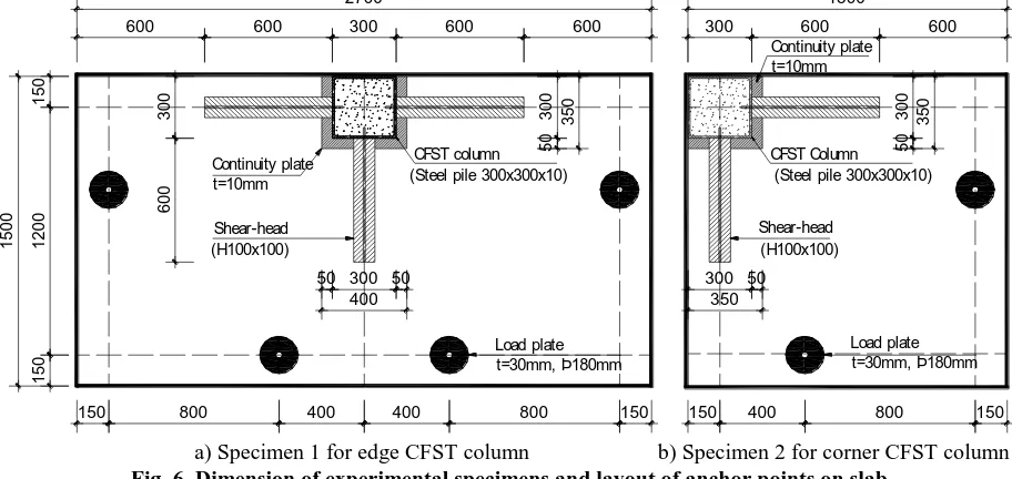
Based on the proposed connection, two experimental specimens designs for the edge CFST column – RC slab connection (Specimen 1, S1) and corner CFST column – RC slab connection (Specimen 2, S2) are made. The specimen dimensions are selected so that their working conditions equivalent to the real slab system with span of 6m and thickness of 200mm (Fig. 5).
4
2
2
3 1
AI
AI A-A
a) Edge CFST column – RC flat slab connection
AI
AI A-A
3 4
2
2 1
[image:2.595.316.533.189.445.2]b) Corner CFST column – RC flat slab connection 1. CFST column; 2. Shear head; 3. Continuity plate; 4. Hole
Fig. 4. Detailed structures of edge and corner CFST column – RC flat slab connection
Analysis of slab model by SAFE V12.3.1 software with distributed load on the floor shows that the points of zero moments are at the distance of 1.2 m from the column. Thus, the sizes of Specimen 1 and 2 are 2.4m×1.2m and 1.2m × 1.2m, respectively. However, as slab anchors need more space, the specimen areas are expanded 150mm on each side, resulting in the final dimension for Specimen 1 of 2.7m×1.5m and Specimen 2 of 1.5m × 1.5m.
[image:2.595.53.289.518.573.2] [image:2.595.334.515.594.722.2]3527
Published By:
Blue Eyes Intelligence Engineering & Sciences Publication
Retrieval Number: B6281129219/2019©BEIESP DOI: 10.35940/ijitee.B6281.129219
To ensure similar behaviors (same forces at the connections) between the test models and the real structures, the number and locations of anchor points on the slabs are
selected to create approximate equal moment values with the moments in the real slab. The analysis results for anchor points layout are shown in Fig. 6.
Load plate t=30mm, Þ180mm Load plate
t=30mm, Þ180mm
150 800 400 400 800 150
2700
600 600 300 600 600
300 150 1500 600 50 300 50 400 300 50 350 Continuity plate t=10mm CFST column (Steel pile 300x300x10)
Shear-head (H100x100)
1200
150
1500
300 600 600
50 300 350 300 50 350 Continuity plate t=10mm CFST Column (Steel pile 300x300x10)
Shear-head (H100x100)
150 400 800 150
[image:3.595.68.524.93.309.2]a) Specimen 1 for edge CFST column b) Specimen 2 for corner CFST column Fig. 6. Dimension of experimental specimens and layout of anchor points on slab
The detailed designs for the two specimens are shown in Fig. 7. CFST column is 300mmx300mm square steel tube with wall thickness of 10mm. Shear-head is H100×100 shaped steel with the length from the column surface of
600mm. The 50mm web of shear-head is inserted into the column through slot on the column face. Shear-head is welded to the outside of the column by 8mm weld.
Shear-head (H100x100)
Load plate
2 - 2 1 - 1
450 600 200 150 150 I1 I1 2I 2I
Þ14a170 Þ14a170
1500 300
200
CFST column (Steel pile 300x300x10)
RC flat slab Load plate
1200 Shear-head (H100x100) Continuity plate t=10mm 50 50 65 100 35 300 900 1500 Þ 14a85 300 Þ 14a85 Þ 14a170 150 900 1350 300 Þ14a85 Þ14a170
Fig. 7. Reinforcement layout for RC flat slab On the sides of the steel pipe, holes of 20mm in diameter
are made for the reinforcement to anchor inside the column. While a steel plate of 340mm × 340mm× 20mm is welded at the foot of the column to place the load jack, the top of the
[image:3.595.80.522.365.738.2]Continuity plate with width of 50mm and thickness of 10mm is welded to the column perimeter at the bottom flange of H100 × 100 shear-head.
The reinforcements of the slab consist of: the upper layer of 14mm steel bars distributed at 85mm intervals for the area near the column and 14mm steel bars at 170mm intervals for the remaining area, and the lower layer of 10mm steel bars distributed at 100mm intervals. There are 2 bars across on each side of the column.
C-shaped stirrup with diameter of 10mm and the length of 6d= 60mm is used. The first layer of stirrup is arranged at distance d/2 =75mm from the column surface, the other stirrup layers are arranged at distances of 100mm (≤ 3d/4 = 112.5). The stirrups are also arranged along both sides of H100×100 shear-head at the distance of d/2 =75mm in order to prevent the inclined cracks near the column areas.
Rings of 10mm diameter reinforced bars are placed on top layer at 100mm intervals. At loading plate locations, additional steel mesh of 8mm steel bars at 50mm intervals are added.
III. MATERIALTESTING
150mm × 300mm cylindrical concrete samples are made at the same time of concrete slab. The samples were cured in laboratory conditions and tested at 28 days of age. The result of the average compressive strength of concrete is 45.14Mpa, and the tensile strength is 3.71Mpa.
Experimental results of reinforcement strength are shown in Table-I.
Table-I: Rebars testing 10, 14 Spec (mm) fy(MPa) fu(Mpa) εy
1 10 421.20 511.3 1.98×10⁻³ 2 14 545.02 662.9 2.50×10⁻³
[image:4.595.317.537.49.261.2]IV. EXPERIMENTSSETUP
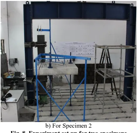
Fig. 8 shows the experimental set up for two specimens so that their behaviors are the same as real structures.
The columns are anchored at the top and bottom by round bars supported by bearings to ensure free sliding in the vertical direction and no horizontal displacement as in Fig. 10.
a) For Specimen 1
b) For Specimen 2
Fig. 8. Experiment set up for two specimens The slabs are anchored by anchor bars (diameter of 36mm) connected to the rigid floor with thickness of 700mm. Specimen 1 uses four anchor bars, Specimen 2 uses two anchor bars. The anchor bars go through the preset holes on the slab and are fixed at the top surface by round plate ϕ180 thick 20mm and anchor bolts. Anchor bars, anchor pins as well as bolts are made of high strength steel. The anchor system at rigid floor is carefully tested to ensure that the anchor system works stably and reliably as shown in Fig. 9.
Fig. 9. Details and testing of anchor on rigid floor Hydraulic jack with lifting capacity P = 2500kN is placed under the column to perform loading. LVDT sensors measure column head and floor displacements. The strain gauges applied on the top and bottom surfaces of slab in a perpendicular and oblique direction measure the deformation of concrete (Fig. 8).
[image:4.595.367.487.382.516.2] [image:4.595.67.268.579.751.2]3529
Published By:
Blue Eyes Intelligence Engineering & Sciences Publication
Retrieval Number: B6281129219/2019©BEIESP DOI: 10.35940/ijitee.B6281.129219
V. TESTRESULTS
Behavior of Specimen 1 for edge CFST column – RC slab connection: By performing load for the specimen with each load level Pi = 20kN, the time to keep the load at each
level is 5 minutes, it can be observed that:
At load level P = 140kN, the first crack appears on the upper surface of the slab and the crack is perpendicular to the outside face. Continuing to increase the load, cracks appear more, continue to develop and run to the free end of the shear-head. On the slab side, inclined cracks appear from the corner of the column with the approximate angle of 450. At load level P = 400kN, cracks widen at positions near the column surface.
[image:5.595.306.549.61.166.2]Continue to increase the load, the displacement of the slab increases rapidly, the cracks at the column edge develop strongly. At P = 430kN, the load does not increase anymore, while the displacement increases fast, resulting in the slab damage. The two floor sections fold to the sides of the shear-head as shown in Fig. 11.
Fig. 11. Behavior at connection of edge CFST column and RC slab (Specimen 1)
Fig. 12a shows the relationship between the load and displacement of the slab. The maximum load value is V= 431.6kN corresponding to the maximum displacement of the column is 43mm.
Fig. 12b shows concrete deformation at the bottom surface, the largest compression deformation occurs at the column face position and gradually decreases when away from the column. At a load of about 350kN, the compressive strain does not increase and reverses to decrease.
a) Load and displacement chart b) Deformations on different positions on slab bottom surface
c) Deformation of the shear reinforcements d) Deformation of the ring reinforcements Fig. 12. Testing results for edge CFST column - RC slab connection (Specimen 1)
Fig. 12c on deformation of the shear reinforcements shows that only two stirrups SS1 and SS5 at the location near the column have large deformations and the plastic strains (εy =
1.98×10⁻³), the remaining shear reinforcements have almost no deformations. This proves that there are inclined cracks cutting through these stirrups.
The deformation of the ring reinforcements in Fig. 12d shows that the cracks cut through all of the ring reinforcements, resulting in their deformations increases. This
proves that the addition of ring reinforcements is necessary. Behavior of Specimen 2 for corner CFST column – RC slab connection:
[image:5.595.75.523.286.649.2]ring layout till to load level P = 113kN. At this load, a long crack appears in parallel with the original one, and passes through the free end of the shear-head.
At the load level P = 133kN, the initial crack widens by 0.5mm, concrete at the column surface has large separation from steel tube with the width of 2mm.
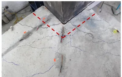
Continue to increase the load, the displacement of the slab increases rapidly, the crack at the edge of the column grows strongly, the external cracks increase insignificantly. At P = 226kN, the excessive slab displacement occurs while the load does not increase and the slab failure occurs (Fig. 13). Fig. 14a shows the relationship between the load and displacement of the slab. The maximum load value is 226,3kN corresponding to the maximum displacement of the column is 64mm.
Fig. 14b on the deformation graph of shear reinforcements shows that only 2 bars SS1 and SS5 at the position of the column have large deformations (εSS1 = 3×10
-3; ε
SS5 =
2.24×10⁻³) and reach plastic strain limit of reinforcement (εy=1.98×10
-3
). This proves the existence of cracks that cuts through the SS1 and SS5 shear reinforcements.
The results of the crack shape analysis in the damage state and the behavior of the reinforcement show that both the edge and corner column occur destructive at the position near the face of Fig. 11, Fig. 13 and the stirrup reaches the yield limit of reinforcement. Therefore, the shear capacity on the critical perimeter includes shear resistance of concrete and stirrup.
Fig. 13. Behavior at connection of corner CFST column and RC slab
a) Load and displacement chart b) Deformation of the shear reinforcement Fig. 14. Testing results for corner CFST column - RC slab connection (Specimen 2)
VI. CONCLUSION
The paper proposes connection structures for edge and corner concrete filled steel tube column and reinforced concrete flat slab, including: H-shaped steel shear-head, continuity steel plate, C-type shear reinforcements, ring reinforcements, longitudinal reinforcement through the column. Experimental program is implemented with two large size specimens. Experimental results show that: the slab is damaged on the critical section near the column surface, the shear reinforcements through this section reach plastic strain of reinforcement, ring reinforcements place active role in radial crack prevention.
ACKNOWLEDGMENT
The authors gratefully acknowledge financial supports from: Technology and Science Research Project funded by Vietnamese Ministry of Education and Training (Grant No. KYTH-43 (B2017.DNA.05)), and Research Project funded
by The University of Danang – University of Science and Technology (Grant No. T2018-02-29).
REFERENCES
1. ACI 318 (2011), Building Code Requirements for Structural Concrete (ACI 318-11) and Commentary, American Concrete Institute. 2. Adel, A. E. and Amin, G. (1996), "Moment transfer by shear in
slab-column connections", Structural Journal, 93(2).
3. Hawkins, N. W. and Corley, W. G. (1974), "Moment transfer to columns in slabs with shearhead reinforcement", Special Publication, 42.
4. Jack, P. M. (1988), "Strength of slab-column edge connections",
Structural Journal, 85(1).
5. John, D. M. and Amin, G. (1991), "Connection of flat plates to edge columns", Structural Journal, 88(2).
6. Marinković, S. B. and Alendar, V. H. (2008), "Punching failure mechanism at edge columns of post-tensioned lift slabs", Engineering Structures, 30(10), pp. 2752-2761.
[image:6.595.326.526.135.262.2] [image:6.595.59.539.310.507.2]3531
Published By:
Blue Eyes Intelligence Engineering & Sciences Publication
Retrieval Number: B6281129219/2019©BEIESP DOI: 10.35940/ijitee.B6281.129219
AUTHORS PROFILE
Dr. Dao Ngoc The Luc, Director, Danang Polytechnic Institute of Science and Technology, The University of Danang – University of Science and Technology, Da Nang, Viet Nam. Luc got PhD in Civil Engineering from Yonsei University (Seoul, Korea) in 2010. Luc’s research interests include structural and computational mechanics, concrete engineering. Luc has published many papers in national and international journals.
Truong Quang Hai, Lecturer,Department of Civil Engineering, Mien Trung University of Civil Engineering, Viet Nam. Hai’s research interests are structural mechanics, concrete engineering. Hai has published many papers in national journals.
Dr. Truong Hoai Chinh, Associate Professor, Department of Civil Engineering, The University of Danang – University of Science and Technology, Da Nang, Viet Nam. Chinh’s research interests are concrete technology, structural engineering. Chinh has published many papers in national and international journals.
![Fig. 1. Experimental result and distribution of shear stress at edge RC column – RC slab connection [3]](https://thumb-us.123doks.com/thumbv2/123dok_us/8154865.248157/1.595.310.546.295.391/fig-experimental-result-distribution-shear-stress-column-connection.webp)