Abstract: NC machine now widely used in industry especially in cutting process. It is precision cutting machine but however the effectiveness of this machine is less effective because it used manual handling to operate. For manual handling, it has many factors that affect the performance of the NC machine. This paper is about to developed of control system for dual NC machine with single 6-axis robot and it is important for further analysis regarding the performance of the machine. 6-axis robot commonly used because it can perform wider of flexibility. To design this system, it consists of integration of multiple controllers and image processing and algorithm for vision is required to differentiate before and after products. A design of automation system must be effective for a better result. This system is served for two NC machine with single 6 axis robot. From the result obtained from this research it showed that by having this system can increase the NC machine rate from 60% to 75% and by developed an automation system shall increase the machine rate into maximum ability of the machine.
Index Terms: NC machine, Automation, Vision system, Robotic, PLC controller
I. INTRODUCTION
To develop automation control system for manufacturing industry it must consist elements of logical control, sequence control, important technology control function and to know the status of each equipment. The key factor of process automation is to setup all the calculation necessary and have all the information needed. Basic construction of automation can be made as several level such as to design basic automation system, process automation system and HMI system, by completed that level of construction, the automation shall perform accordingly [1].
As the change of time, the industry now is moving towards into industry 4.0. As perspective of industry 4.0, it will create an opportunity for sustainable manufacturing industry in term of economy, environment and communication and as the theme suggest all the automation shall be as easy as push a single button to start any process [2].
Revised Manuscript Received on December 05, 2019.
Mohd Aliff, Senior lecturer, Instrumentation and Control Engineering Section, Malaysian Institute of Industrial Technology, Universiti Kuala Lumpur, Malaysia.
Abdul Halim Hamdi, Master Engineering Technology, Electrical Student, UNIKL.
Ismail Yusof, Head of Section of Instrumentation and Control engineering, Malaysian Institute of Industrial Technology, Universiti Kuala Lumpur, Malaysia.
Nor Samsiah, Senior lecturer, Faculty of Information Science & Technology, Universiti Kebangsaan Malaysia (UKM).
Many level of industry have started to moved towards industry 4.0 because of the traceability can be acquired easily and also it is one of the requirement to be a smart factory and ensure the process flow more reliable [3].
To develop cost effective solution for productivity can be achieve by develop a system that integrated with a robotic system [4]. A robotic automation is one of the solutions to replace the human being as the robot will constantly repeated their work without any justification and objection. Furthermore, in the market now already served a high quality of the system in term of efficiency, accuracy, repeatability and others. By replacing human with the robotic system shall increase the effectiveness of the machine because by using robot as the part of automation can make the process more efficient [5]. 6-axis robot are designed to perform a complex task and still delivered the desired outcome. The optimized of each joint can be improved as necessary [6].
Multiple controller is required to communicate with each other, there are several types of protocols can be performed. Ethernet/IP protocol one of the solution to integrated all controller into a single system [7]. This Ethernet/IP or Ethernet/Industrial Protocol had been develop since 2001 by Rockwell Automation and it is feasible to used especially in PLC controller [8].
Vision system is a compatible replacement for human eye because this image processing is used algorithm to detect something compared to human judgement that sometimes effected if the concentration disrupted [9]. Image processing offered a high precision result and it evolved the inspection method in industrial sector for the last decade [10]. With a correct algorithm, a coordinate of material can be detected and transferred to other controller [11].
Nowadays technology offered a lot of flexibility and by adapt with the changes it can help reduce the downtime and increase the productivity [12]. Robotic machining one of the solutions for many types of level in precision cutting industry such as lathe, milling. The architecture for this development consist of various controller [13]. By developed an automation system it can increase the production output rate. Equation (1) is to determine the yearly productivity produced by these machine, where
is machine running hour,
isworking days,
is working month,
is machine quantity,
is monthly average setting time,
is setting hour,
is reload hour and
is average cycle time.Development of Control System for Dual NC
Machine with Single 6-Axis Robot
machine. Nevertheless, this system is not limited to NC machine only and it can be implemented to others machine that suit with the capability.
II. METHODLOGY
A.System Concept
PLC has more of advantages compare to the limitation of it and some of advantages of a PLC:
It has noise protection
Addition of units (e.g I/O)
Normal I/O connection and signal
[image:2.595.74.256.364.569.2]Even though PLC has been develop in late 60’s it is still one of major controller for any automation system regardless in any kind of industry level [14]. PLC can be integrated with many types of controller as shown in Fig. 1.
Fig. 1 Integrated System
For this system, controller is integrated with several type of controller as shown in Table 1.
Table. 1 Main controller to integrate
No Part Name Manufactur
er
Model Number
1 Vision
controller Keyence CV-X150A
2 3 4 5 6
Robot controller
PLC controller Servo driver PLC controller Stepper Driver
Epson Mitsubishi Mitsubishi Mitsubishi Oriental Motor
RC-700A FC3G-60M T
SGD7S FX3G-40M T
[image:2.595.376.476.393.562.2]RKSD507M
Fig. 2 Source code for vision
Commonly, PLC based automation system is integrate with HMI for make the system more user friendly [14]. Basic operation of HMI is shown in Fig. 3. This HMI will plays vital task between the operator and automation system [15].
Fig. 3 Major process of HMI [15]
To achieve the objective for this automation system, the 6-axis robot must have the ability to pick and place the products. In order to that, designed for gripper is essential because it is the tool to perform the desired task [16]. As shown in Fig. 4 is the concept for gripper. It has 3 function:
[image:2.595.49.288.652.788.2]Fig. 4 Gripper design
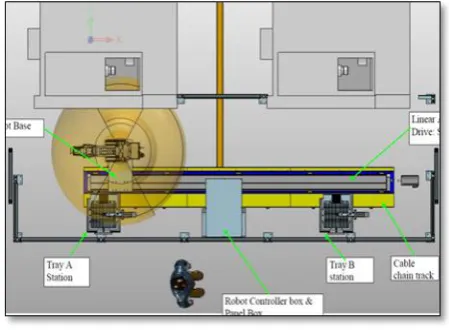
[image:3.595.120.219.52.177.2] [image:3.595.57.279.338.719.2]The layout for automation system is presented in Fig. 5 to Fig. 7 as the access into machine area is using right and left of NC machine and the robot itself it mounted at linear motor in front of the machine. Vision system is placed at the tray A and tray B area where the robot will pick and place the materials. Robot vision systems play an important role in the robot pick-and-place task. They can be used to detect objects, and to measure their location [17]. This vision system is commonly used in industry for a replacement with human eyes because it has the precision technology. In front of this system is a loader A and B. This loaders for load and un-load the material. Each loader can load for 20 tray per time.
Fig. 5 Automation layout (a)
Fig. 6 Automation layout (b)
Fig. 7 Automation layout (c)
B.Electrical concept
Fig. 8 Electrical design
[image:3.595.55.280.341.506.2]This system is operated by 200 VAC as shown in Fig. 8 and for each equipment are designed to be protected by earth leakage circuit breaker (ELCB) and miniature circuit breaker (MCB). These 2 devices are installed as a precaution if any abnormality happened from the power source and the system itself. Safety regarding electricity shall be properly taken care because electrical leakage is not something normal eyes can detect it. Nowadays, there is technology available to detect any failure happened at the system and it is one of the solution to protect people from electrical hazards [18].
[image:3.595.318.533.579.716.2]compulsory for industry to comply this regulation. On top of that, exhaust fan is installed to make sure the good ventilation to stabilize the temperature inside the panels. All wires carry a heat that generated from the current. It is essential to make sure that this panel are in an appropriate size. This system also equipped with sensors and actuator.
1.Proximity sensors (Omron E2E-X2Y)
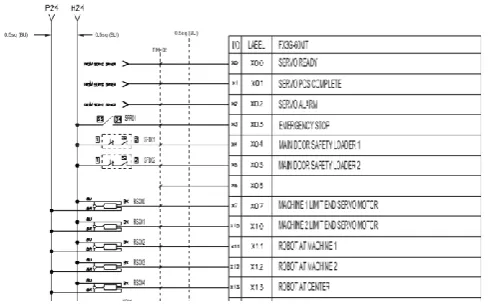
[image:4.595.307.540.122.195.2]Proximity sensor commonly used because of the characteristic of this sensor that can operated in oily environment. The application for this sensor also suitable for many operation [19]. As for this system, this proximity used for positioning the location of the robot as shows in Fig. 10 the connection of these sensors to PLC.
Fig. 10 Proximity sensor connection
This sensors specification are written below: Sensing distance: 5 mm ±10%
Set distance: 0 to 4 mm
Detectable object: Ferrous metal
Power supply voltage: 24 to 240 VAC, 50/60 Hz
2.Reed switch (SMC D-M9NE)
Reed switch sensor commonly found in pneumatic system. It is one of the solution to confirm the position of the cylinder. Before the process can proceed to another task, a confirmation signal from reed switch is required. The fundamental construction of reed switch is using an electromagnetic theory [20]. The wiring diagram is shown in Fig. 11.
[image:4.595.46.292.319.472.2]Fig. 11 Reed switch connection
Fig. 12 Photoelectric sensor connection
4.Stepper motor (RLSD507M-C)
[image:4.595.322.528.348.495.2]Stepper motor is an open loop actuator where it can drive the motor without giving back the actual positioning to the controller. It is drive by given a pulse output from the controller to move and control the speed of the motor. This stepper motor usually used for a positioning process and it consist of multiple stator for a precision positioning [22]. As shows in Fig. 13 is a connection from the driver to the PLC controller. Stepper motor also equipped with an electromagnetic brake to prevent the actuator from move if not in operation
Fig. 13 Stepper motor connection
This sensors specification are written below:
Power supply voltage: Single phase 110 VAC, 50/60 Hz Rated current: 0.75 Amp
Maximum holding torque: 1.77 N.m Step angle: 0.72°
C.Software Architecture
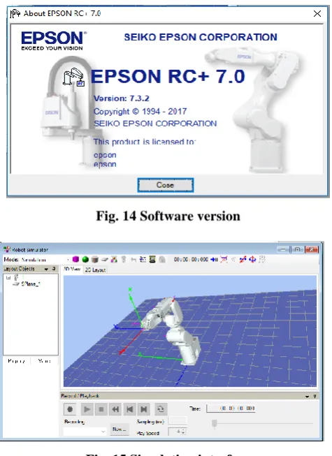
[image:4.595.56.282.676.757.2]Fig. 14 Software version
Fig. 15 Simulation interface
[image:5.595.355.501.56.201.2]Because of this system used 6-axis robot it is crucial to run the simulation to foresee the movement and also the limitation of degree freedom. This software allowed CAD file to be uploaded and 3D model of NC machine can be seen in the simulation. The trajectory of this robot also can be run and to see the path from point to point as shown in Fig. 16.
Fig. 16 Trajectory path
III. RESULT
To achieve the objective of this research, integration of multi controller between PLC, vison controller and robot controller must be established. The ideal distance of camera placement is shows in Fig. 17.
Fig. 17 Camera working distance
[image:5.595.312.543.290.418.2]Integration between this controllers can create efficient system [24]. From previous research, to develop machine vision with PLC controller can be made but it required an image process algorithm to recognize the burr on metal and sorting it [25].
Fig. 18 NC machine rate
This machine rate productivity is consisting of running hour for 23 hours per day running. From Fig. 18, shown 2 types of data, manual operation and single robot operation. Manual operation is categorized into 3 type of material, case frame, bezel case back and bezel. It showed that inconsistency of machine rate productivity as the data from April 2017 to March 2018 is taken. The sample product produced by this NC machine is shown is Fig. 19. By develop an automation system it can increase the machine rate because of the efficiency of automation is reliable.
Fig. 19. Part produced
[image:5.595.55.286.467.603.2]Fig. 21 Stop loss
[image:6.595.55.289.276.412.2]Manual operation suffers a loss of time running because 2 major factor which is management loss and stop loss. From the 2 major factor it has own sub categorized as shown in Fig. 20 and Fig. 21.
Fig. 22 Results
After collected data for 4 months from August 2018 and November 2018 it showed that 15% or 19266 pieces increase from 60% or 128440 pieces from manual handling as shows in Fig. 22. It proved that the effectiveness of this NC machine can be increase by implemented this system. Equation (1) is to determine pieces produces yearly by manual and automation system by using parameters in Table 2.
Table. 2 Parameters system
No Items Manual Automation
1 Machine running hour 21.5 23
2 3 4 5 6 7 8 9 Working days Working month Machine quantity Setting hour Average setting frequency/Month Average setting frequency/Day Reload hour Average cycle time
22 12 1 1 200 9.09090 909 0.00416 667 2.75 22 12 2 1 200 9.09090909 0.0125 2.75 IV. CONCLUSION
Overall, development of the control system for dual NC machine with single 6-axis robot can be seen after development of the automation. This system consists of multiple controller and can be integrated to each other for achieve the objective of this research. This system also is not limited to this particular material and can be used for any other suitable material with a change of few parameters. Vision system proved that it has the capability to help created
The author would like to thank the research management center of Universiti Kuala Lumpur, for managing the project.
REFERENCES
1. Z. J. Jiao, C. Y. He, J. Wang, and Z. Zhao, “Development and application of automation control system to plate production line,” 11th Int. Conf. Control. Autom. Robot. Vision, ICARCV 2010, no. December, pp. 678–681, 2010.
2. T. Stock and G. Seliger, “Opportunities of Sustainable Manufacturing in Industry 4.0,” Procedia CIRP, vol. 40, no. Icc, pp. 536–541, 2016. 3. L. Bassi, “Industry 4.0: Hope, hype or revolution?,” RTSI 2017 - IEEE
3rd Int. Forum Res. Technol. Soc. Ind. Conf. Proc., 2017.
4. L. Pérez, E. Diez, R. Usamentiaga, and D. F. García, “Industrial robot control and operator training using virtual reality interfaces,” Comput. Ind., vol. 109, pp. 114–120, 2019.
5. M. Findeisen, M. Todtermuschke, R. Schaffrath, and M. Putz, “A method for energetic comparison of 6-axis industrial robots and its further scope for resource-efficient plant design,” Procedia Manuf., vol. 21, pp. 251–258, 2018.
6. H. Min Jo et al., “Optimal wrist design of wrist-hollow type 6-axis articulated robot using genetic algorithm,” Proc. 2018 IEEE Int. Conf. Mechatronics Autom. ICMA 2018, pp. 1486–1491, 2018.
7. Zhihao Ling and Jinshou Yu, “The design of SCADA based on industrial Ethernet,” pp. 2786–2789, 2003.
8. E. Alessandria, L. Seno, and S. Vitturi, Performance analysis of Ethernet/IP networks, vol. 7, no. PART 1. IFAC, 2007.
9. J. F. Shi, C. J. Hua, and G. H. Li, “A simplifying method of vision attention simulating human vision in machine vision system,” 2010 Int. Conf. Mach. Learn. Cybern. ICMLC 2010, vol. 6, no. July, pp. 3097–3100, 2010.
10. J. Jia, “A machine vision application for industrial assembly inspection,” 2009 2nd Int. Conf. Mach. Vision, ICMV 2009, pp. 172–176, 2009.
11. F. Zhong and C. Quan, “Digital image correlation in polar coordinate robust to a large rotation,” Opt. Lasers Eng., vol. 98, no. May, pp. 153–158, 2017.
12. N. Girish, K. M. Subbaiah, and K. Upendra, “Establishment of backup system for failed NC robot,” pp. 338–342, 2014.
13. A. Verl, A. Valente, S. Melkote, C. Brecher, E. Ozturk, and L. T. Tunc, “Robots in machining,” CIRP Ann., 2019.
14. E. R. Alphonsus and M. O. Abdullah, “A review on the applications of programmable logic controllers (PLCs),” Renew. Sustain. Energy Rev., vol. 60, pp. 1185–1205, 2016.
15. V. M. Koshti and S. M. Joshi, “Design of Human Machine Interface for Plc Based Automation System,” IFAC Proc. Vol., vol. 40, no. 18, pp. 343–346, 2010.
16. R. Shah and A. B. Pandey, “Concept for Automated Sorting Robotic Arm,” Procedia Manuf., vol. 20, no. 2017, pp. 400–405, 2018. 17. H. I. Lin, Y. Y. Chen, and Y. Y. Chen, “Robot vision to recognize both
object and rotation for robot pick-and-place operation,” 2015 Int. Conf. Adv. Robot. Intell. Syst. ARIS 2015, pp. 1–6, 2015.
18. N. M. Nor and T. Ibrahim, “Domestic Application,” no. June, pp. 23–28, 2013.
[image:6.595.56.281.526.661.2]20. P. Regtien and E. Dertien, Inductive and magnetic sensors, vol. 1, no. C. 2018.
21. M. G. Shahril Shah, A. B. Elmi, A. Nazir, and S. Shukri, “Photoelectric sensor based intelligent track racing car,” Procedia Eng., vol. 41, no. Iris, pp. 588–592, 2012.
22. F. Nickols and Y.-J. Lin, Theory III: The Stepper Motor and Its Control. 2019.
23. C. Xiaowei and S. Chuanwei, “The study of robot simulation applications based on the LabVIEW robotics,” ICCSS 2017 - 2017 Int. Conf. Information, Cybern. Comput. Soc. Syst., pp. 66–71, 2017. 24. S. Chen, X. Qian, and M. Zhou, “Research of automation steel tape
measurement system based on PLC and computer vision technology,” 2009 WRI World Congr. Softw. Eng. WCSE 2009, vol. 1, pp. 251–255, 2009.
25. L. Peilin, Y. Zhen, Z. Wenlong, and L. Hong, “An automatic sorting system for sorting metal cylindrical workpiece based on machine vision and PLC technology,” 2017 2nd Int. Conf. Robot. Autom. Eng. ICRAE 2017, vol. 2017-Decem, pp. 446–450, 2018.
AUTHORSPROFILE
Mohd Aliff is currently a senior lecturer of Instrumentation and Control Engineering Section, Malaysian Institute of Industrial Technology, Universiti Kuala Lumpur, Malaysia. He received his doctor degree in Engineering from Okayama University of Science in 2016. His research backgrounds are in mechatronics and robotics; particularly in rehabilitation device, intelligent robot and flexible pneumatic actuator. He is a member of Board of Engineers Malaysia and Malaysia Board of Technologists.
Abdul Halim Hamdi is a Master Engineering Technology in Electrical student at UNIKL. He also is an electrical project engineer and has been involved in automation projects since 2016. He is graduated from UNIKL with his course is Bachelor Engineering Technology in Electrical in 2016.
Ismail Yusof is currently a Head of Section of Instrumentation and Control engineering, Malaysian Institute of Industrial Technology, Universiti Kuala Lumpur, Malaysia. He received his Bachelor of Engineering Technology (Mechatronics) from the Universiti Kuala Lumpur-Malaysia France Institute (UniKL MFI) and PhD in Automatic Control & Systems Engineering from the University of Sheffield. His research interests in Control System with Application in Robotic.
![Fig. 3 Major process of HMI [15]](https://thumb-us.123doks.com/thumbv2/123dok_us/8155881.248410/2.595.376.476.393.562/fig-major-process-of-hmi.webp)