International Journal of Innovative Technology and Exploring Engineering (IJITEE) ISSN: 2278-3075, Volume-8 Issue-8, June 2019
Is-Is Protocol Model Suite: Simulation of
Implemented Features and Their Configuration.
Arif Sari, Joshua Chibuike Sopuru, ÖnderOnursal
Abstract: In recent times, the Intermediate System to Intermediate System (IS-IS) protocol gains more attention from network administrators and users alike. As many service providers engage in the active usage of this protocol, the IS-IS protocol has unfolded a new stream of research regarding its applicability in different scenarios. In contrast to existing distance vector protocols, the IS-IS In basic terms is a link state protocol (LSP) supporting extremely large networks. It is also known for its robustness and an easily adaptable protocol powering cutting edge technologies like the Multiprotocol Label Switching (MPLS), a system used for traffic engineering. A major reason in considering wide application of the IS-IS protocol is its ability to efficiently move large chunk of data within group of connected computers or within a network(area) and still achieving best route for data delivery. Because of the ability of the Optimized Network Engineering Tool (OPNET) to effectively study the internal operations of a simulated network, we conducted experiments using OPNET to demonstrate various implemented features of IS-IS and to explain their configuration.
I. INTRODUCTION
When looking at routing protocols, a very critical question comes to mind: "Which protocol to use?". The full-evidence approach to use is to set up a system and utilize the conventions that may conceivably suit the system's needs. This will end up being incredibly wasteful and costly in time, cash and assets. To give a response to this inquiry, simulation come into play. System simulation is a strategy for demonstrating the conduct of a system by figuring the collaboration between the distinctive system elements, utilizing numerical equations, or changing system composition, conventions or protocols in other to test the desired network. Such simulation can be performed by different software, (for example, OPNET, ns, NetSim and so forth.) also called network simulators. A simulation system is a software intended to evaluate the behavior of a network, arranged by assessing the execution of a model that relates to the system that should be developed. For this situation, the OPNET simulation system was used to demonstrate various implemented features of IS-IS, and to describe how to configure and study the IS-IS model. IS-IS is a routing protocol designed based on the DECnet phase V routing. Here routers referred to as intermediate systems exchange routing information via a line metric in other to learn a networks’ topology. IS-IS routing protocol is like the Open Shortest Path First (OSPF). OSPF has an original specification, the ISO 10589, which describes how IS-IS is used for routing based on the ISO Connectionless Network Protocol. Later, IS-IS was enhanced to allow for routing in IP Networks.
Revised Manuscript Received on June 7, 2019
Arif Sari, Department of Management Information systems The American University, Cyprus
Joshua Chibuike Sopuru, Department of Management Information systemsThe American University, Cyprus
ÖnderOnursal, Department of Management Information systems The American University, Cyprus
This is widely known as Integrated IS-IS and was also specified in RFC 1195. One major importance of the IS-IS is its ability to engage large networks yet following the Dijkstra algorithm of shortest path first (SPF) delivery. IS-IS can also be referred to as a link state routing protocol (LSP). LSPs are obviously very complex and substantially hard to implement, manage, and analyze for this reason, the goal of this article is to provide a guide for effective network layout design using the IS-IS protocol. The remaining parts of this article is organized as follows: Part II introduces the IS-IS Protocol model suite with reference to previous works done, Part III explains features of IS-IS protocol, Part IV presents the simulation results and findings, and Part V is the conclusion and guide for further studies.
II. IS-IS Routing Protocols
As an LSP, IS-IS offers a wide range of features. Due to the scope of this article, we will focus on the following features of IS-IS:
IS-IS uses a Network Entity Title (NET0 belonging to the OSI network addresses.
A minimum of one NET must make up a functional IS-IS.
IS-IS allows for the configuration of Two-level hierarchy
Routes within an area is maintained by a Level 1 while routes between areas are maintained by Level 2 routers.
A. How IS-IS operate
Using SPM, forwarding is based on a calculated shortest-path. This implies, the shortestpath is determined to ensure effectiveness of packet delivery. On a mesh topology, support for massive layer 2 topologies are provided by SPM from a high level, IS-IS operates in the following way:
Neighbors are adjacencies are separated by transferring Hello packets from one IS router to another.
Neighbors are established if there is a response received after an initial Hello packet has been sent.
A link state packet (LSP) is then built based on prefixes data and nearby connections of routers.
Routers within an LSP setup databases to form the LSP network.
The easiest and shortest way of routing paths are created from creating the shortest part table (SPT). [1]
B. Interior Routing Protocol
Based on operations, behavior and need, routing protocols can be grouped. Based on purpose, the Exterior Gateway Protocol (EGP) and Interior Gateway Protocol can be grouped while the Link-state protocol, path-vector protocol and distance vector protocol can be grouped in respect to their different operations. Arranging routers in a known institution is referred to as autonomous system (AS). Case of such basic organization incorporates an association or an organization. An ISP's system or the inward system of an organization are instances of an AS. Based on the interior gateway and the exterior gateway protocol, the Internet is built. IGPs are actualized for steering in AS. This idea is alluded to as intra-AS directing. A few types of intra-AS directing incorporate the Open Shortest Path First (OSPF), Routing Information Protocol (RIP), Enhanced Interior Gateway Routing Protocol (EIGRP) and Intermediate System to Intermediate framework convention (IS-IS). Associations and specialist organizations use these protocols. EGPs are then again utilized for self-ruling framework routing. This type of routing is otherwise called between AS routing. EGP can be utilized as an interconnection for organizations and specialist co-ops for this situation. For this situation, the EGP which is the official website routing protocol is the Border Gateway Protocol (BGP). [2]Host to host communication is made possible by theInterior Gateway Routing Protocol (IGRP). IGRP was made by Cisco to deal with the constraints saw in Routing Information Protocol (RIP). With this improvement IGRP can deal with a most extreme jump tally of 255 contrasted with the underlying 15 tally taken care of by RIP. IGRP accomplishes two primary objectives:
1.Pair routing data to switches associated inside its independent framework or limit. 2.Update ceaselessly if a change happens in the system way. At regular intervals, IGRP refreshes every single associated switch on changes inside the system. A routing table containing the records of ideal ways to hubs is organizedand overseen by the IGRP. As a separation vector convention, far off parameters are used to decide best way to goals. Transfer speed, load, deferral, unwavering quality and Maximum Transmission Unit (MTU) are a portion of the parameters utilized by
IGRP. [3] For data transmission, dependability, internetwork postponement and burden, IGRP uses a composite measurement inferred dependent on the figuring of weighted qualities. The weighting component can be characterized by managers for every measurement. Rules ought to be carefully clung to before changing any esteem. Dependability and burden bear esteem some place in the scope of 1 and 255; information exchange limit can take esteems that are reflecting velocity from 1200 bps to 10 Gbps, while slacks can take on any impetus from 1 to 224. These wide estimation ranges are furthermore enhanced by a movement of client recognizable constants.
The constants are hashed against the measurements in a calculation that yields a solitary, composite measurement. The system chairman can impact course choice by giving higher or lower weighting to a measurement.
The IGRP grants a few portals to deal with their directing for certain reasons:
1. Stable steering complex frameworks. 2. No steering hovers should occur.
3. Rapid response to changes in framework structure. 4. Low overhead. IGRP should not to use a bigger number of information exchange limit than required for its task. 5.Dividing traffic among a couple of courses with equivalent alluring quality.
6.Taking into record botch rates and measurement of traffic on different ways.
International Journal of Innovative Technology and Exploring Engineering (IJITEE) ISSN: 2278-3075, Volume-8 Issue-8, June 2019
Utilizing information from the complete network, each gateway optimizes an arrangement from its start point. Each approach has a few points of interest. In a few cases, SPF reacts rapidly to changes. To dodge directing circles, unused information is overlooked for a few minutes after changes has been actualized. SPF gets data straight from each portal. This makes a difference to overcome routing circles. Modern data can be designed to send instant messages. .IGRP presents several features designed to achieve stability and promote general network enhancement. Some of these features are split horizons and holddowns.
Holddowns:In other for messages that update frequently not to attempt contacting a dead route, holddowns are used. When a router is down, the routers in the network learn a router is down by their inability to receive messages that had been scheduled. On the discovery of a dead route, new routes are automatically computed and information about this new route disseminated across the network. Such information triggers automated updates within the entire network. Since the information do not arrive on all the nodes at the same time, devices that have not been informed about the failure may attempt to send information via a failed route. In this situation, correct routing data will be delivered to the node. With Holddowns, routers are informed to delay in other for the changes in route to be updated before sending a message.
Split horizons:For every issue there is a reason. The split horizon keeps record of the reason behind a route failure. For example, when a route R1 communicates to a network A, there might be no reason for route R2 to recommunicated with R1 because the route R1 has a better proximity to the Network A. In principle, we can say R2 connects with the available route based on future updates delivered to R1 when the proximity is lower. Enough distance is maintained by the split horizon technique to manage routing flow. Holddowns and split-horizons help in maintaining a unique algorithm [4]
C. DVR or Distance Vector Routing Protocols
This is a form of distributed routing protocol. It allows routers to automatically discover routes or destinations that are reachable within a network. Based n DVR protocols, the shortest path to the best destination can be calculated using associated metrics. [5]The distance vector protocol was originally developed for smaller networks. Examples of such protocol incorporated are the IGRP and RIP. Because of their size and their target network, the IGRP and RIP are easy to develop and implement. They also do not require any extra support other than a connection-state protocol. However, they utilize high CPU resources and require noticeably high transfer speed. Because of these requirements, the distance vector protocol is not as advantageous as the link state protocol considering combination time. Using Hop counts, the distance vector protocol can compute the best possible route available with a network. Hop count is the total sum of routers a packet
will have to pass through while traveling from host A to B. Using a ‘telnet’ command, a hop count can be determined. If a host node sends a telnet to another host and the packet is supposed to pass through 4 routers, then the Hop count is equal to 4 Selecting the shortest possible path by a distance vector protocol can pose some problems. For example, a path having the shorts Hop count may not represent the best path a packet can take. Consider this situation, say a host A is attempting to send a packet to another host B and along the selected path, the Hop count is one. However, the router on this path has a lower speed compared to a router on another path with two Hop counts but a better dial-up speed. Following this algorithm, it is of no doubt that the path with one hop count will be selected even though this path may not be as fast as the path with two hop counts. [6]
D. Routing Information Protocol (RIP)
RIP is a distance vector protocol and was developed to manage smaller networks. Because of its many limitations, the RIP has been marked as not fit for most TCP/IP configurations. Like other distance vector protocol, RIP finds the best possible path also by considering the number of Hop counts present in the route. With this configuration, the number of gateways RIP can manage is limited to a maximum of 15 On a RIP router, every 30 seconds, information is broadcast to all networks that are directly connected. Information in this message are used to keep the routing table updated at all time. A range of 180 seconds is set for each RIP router to communicate with its neighbor, if after the 180 seconds a nonboring router fails to receive update information, the RIP router considers its neighbor as dead. It then sets all routes through that router to be disabled and stops using that route. After an additional 120 seconds and no update message has been received from the router, all routes via that neighboring router is then deleted from the routing table. [7]
Neighbor Discovery/Recovery: Since new routers can be attached to an existing network over time, it is important for routers on the network to be able to learn when a new router
has been added to the network. Neighbor
Discovery/Recovery is the capability of routers in a network to learn about the addition of a new router. This is done dynamically to synchronize the entire network. To achieve this, routers send a “Hello” message in other to understand the current state of its neighbor. If a message received notification is gotten by the sender, the router learns that its neighbor is active. When routers confirm the activeness of their neighbor, communication can then begin. However, establishing such connection is not just the main aim, there is need to ensure a reliable delivery of packets. Reliability of packet transfer for some packets is important whereas such reliability check might not
EIGRP packets require stringent reliability checks. This reliability is ensured through reliable transport mechanism. On a multicast network however, reliability check might not be necessary as one “hello” message confirming that the sent package does not need to be recognized is sent to all nodes at once. On the other hand, for update packets, acknowledgement is usually required. Decision making and monitoring of available routes are incorporated in a DUAL finite state machine. Best free paths are selected using metrics. Considering possible route with routing paths, routes are selected to be added to the routing table. Addition of possible routes to the routing table goes on and on as long as new routes become available. During the recompilation of the routing table, a new route satisfying the least cost path available is assigned. Due to recompilation of this routing route, convergence time might increase because of this, recompilation is recommended to be avoided as much as possible [8]
E. Link State Routing Protocol
The link state routing protocol is designed for enterprise-level systems. These protocols are complex and more difficult to install than previously discussed protocols. They are also more difficult to manage and require greater commitment in investigating their operations in contrast to the distance vector protocols. Despite its complexity, this protocol is important and play major role in the implementation of larger networks as it overcomes many noticeable weaknesses of distance vector protocols
For the link state protocol, a totally different algorithm is implemented for computing the shortest and best path to a destination. In this algorithm, more features such as bandwidth of the network and other impacting features are considered. In addition to the importance of link state protocol over distance vector protocols, convergence happens faster in the link state protocol than in the distance protocol. The reason behind this faster convergence is because, the link state protocol establishes relationships based on peers that are directly connected and information are shared with neighbors only when there is a change in the overall network topology. [9]
F. Open Shortest Path First
The open shortest path first (OSPF) is an algorithm for the dissemination of information via the shortest route within an autonomous system. The OSPF algorithm resulted to the development of the Internal Gateway Protocol (IGP) which is a functional OSPF algorithm.
Unlike the RIP, OSPF has better convergence. This is because changes because of routing are updated quickly rather than occasionally. As a result, the OSPF takes into consideration better load balancing. [10]
G. S-IS Areas and Routing Hierarchies
After considering several routing protocols and how they relate to the IS-IS protocol, it will be proper to understand IS-IS routing hierarchies and location.
Same identifiers (ID) classifier a group or set of routers. That is, when sets of routers are arranged within a given area, they can be identified by a unique ID. Since IS-IS routers are assigned to physical locations each location is identified by the information contained in the Network Service Access Point (NSAP). For networks set up in multiple locations, different NSAPs routers can be implemented. Each network will have different IDs but same system identifiers (sysID). However, the IS-IS router merges all areas into one physical area. Routers participating in the same location are referred to as level 1 routing whereas routers participating across two or more areas are referred to as level 2 routers [11]. The connectionless network layer protocol (CLNP) makes it possible for the collection of SysID and adjacency information. Routers between territories may have neighbors and each neighbor have information regarding the level 2 topology and contain information on the routes accessible by means of level 2 route. Routers with the territories do not need to know the topology in the level 1 area. Information packets can be passed directly from an area to other routers situated outside the area. [12] Configurations of Cisco routers with IS-IS protocol can be done either by level 1-only configuration, level 2-only configuration or both. By default, the cisco routers come configured with both L1 and L2 capabilities. However, each level can be disabled. Caution should be taken if any level needs to be disabled as this might affect the entire network if done wrongly.
H. IS-IS Packets and Packet Format
Understanding packet format and the IS-IS packets is important before we move into more complex IS-IS notions. The knowledge of the basic components and workability of the IS-IS protocol will give us better understanding of the protocol and its application.
In IP and CLNP protocols, transmission of data is done as packets. Based on the ISO 10589 standards, packets are described as protocol data units (PDUs). More than one type of packets is used in a connectionless environment. [13]
The IS-IS packets consist of three different categories of:
1. “Hello/state Packets” 2. Link-state packets and 3. Sequence number packets.
International Journal of Innovative Technology and Exploring Engineering (IJITEE) ISSN: 2278-3075, Volume-8 Issue-8, June 2019
Each IS-IS share same header. IS-IS utilizes the following PDUs to exchange information.
IS-IS Hello (IIH) DUs: The active state of each neighbor can be determined by sending this PDU to each neighbor. The Hello PDU is also used in understanding the level of the IS-IS system.
III. Intermediate System to intermediate System (IS-IS) features
Intermediate systems are more than a router referring to a node. It covers the recognition of individual routers or hubs within a network. IS-IS makes it possible for routers to identify each other. It performs similar roles as nodes engaged in a routing process just as other routing protocol. Conditions regarding links and their usage is effectively managed and stored by the IS-IS protocol. This information enables the IS-IS in choosing the best path for routing. The IS-IS protocol transmits link state data to the entire network thereby keeping all router updated with routing information [15]. Internet service suppliers (ISPs) have the potential of shaping a few Virtual routing and forwarding (VRF-aware) IS-IS occasions running on one router, rather than multiple routers. ISPs utilize this feature to partition client data while including the information to providers. [16]
Other features of IS-IS other than the once listed at the beginning of this section include:
1. Hierarchical routing 2. Classless behavior
3. Rapid flooding of new information 4. Fast Convergence
5. Very scalable 6. Flexible timer tuning
IV. Simulation Experiment
OPNET 14.5 simulation software was used to simulate the IS-IS network. OPNET simulates network performance and behavior, one of its major advantage over existing network simulators is its versatility and power. OPNET has also been used in physical layer attacks in MANET [17] and has produced outstanding results. Considering the IS-IS network, the OPNET simulator is considered a fit for this reason.
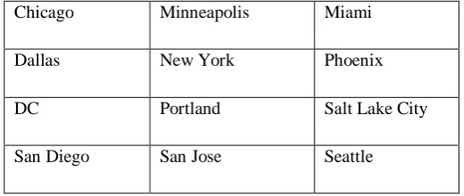
Some simulation objects used for router locations is listed in the table 1 below
Table 1: Distribution of intermediate devices.
Houston Kansas City Las Vegas
Atlanta Denver Detroit
Boston Indianapolis Los Angeles
Chicago Minneapolis Miami
Dallas New York Phoenix
DC Portland Salt Lake City
San Diego San Jose Seattle
Using OPNET, Level 1 locations for routers within a location was set with parameters assigned and level 2 locations of routers within a distance locations (domains) were also configured. Some communication parameters of routers are represented in the snap screenin figure 1 below
Fig 1. Simulation parameters used for routers
Different configurations were given participating routers and nodes thereby ensuring a real operating environment was replicated in OPNET.
For participating routers, packet types of level 1 and level 2 routing were also assigned. Hello Packet, forwarding and delivery were also monitored in OPNET.
[image:5.595.297.557.50.160.2]The following Table 2 shows IS-IS packet types:
Table 2. ISIS packet types
Category Packet Type Type Number
Hello LAN Level-1
Hello
15
LAN Level-2
Hello
16
Point-to-point Hello 17
LSP Level-1 LSP 18
Level-2 LSP 20
PSNP Level-1
Complete SNP
Level-2 Complete SNP
25
Level-1
Partial SNP 26
Level-2
Partial SNP 27
This research simulation was conducted in four differentScenario (environments)focusing on different features of IS-IS.
Scenario 1. Simple configuration
This scenario depicts a simple configuration, with no hierarchy. To enable IS-IS for routers and have it exchange routing information with other IS-IS enabled routers, you must performfollowing two tasks.
1) Configure Network Entity Title (NET)
2) Enable IS-IS for IP routing on an interface
Other configuration tasks are optional; however, the above two tasks are required.
With simple, no hierarchy configuration, all routers must maintain all routes hence a routing table size tends to be large and the network will likely encounter scalability problems as it grows.
See the routing table of Seattle below.
[image:6.595.42.293.48.176.2]COMMON ROUTE TABLE snapshot for: Router name: Seattle at time: 3600.00 seconds
Fig 2: Routing table depicting a simple configuration
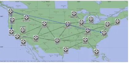
The simulation environment of a simple configuration is shown in the figure 2 below
Fig 3. Simulation environment for a Simple configuration Scenario
Scenario.2: hierarchical network
This scenario depicts the same network as in the simple configuration scenario, but with hierarchy configured.
IS-IS supports a two-level hierarchy. A routing domain is partitioned into areas. Routers belonging to a common area and engaged in Level 1 routing are referred to as Level 1 routers. Level 1 routers in a common area need to share a common area ID. They maintain all routes inside their area but don't know routes outside of their area. They simply forward all traffic for destinations outside of their area to the nearest Level 2 router in their area.
Routers in different areas exchange routing information through Level 2 routing and are referred to as Level 2 or backbone routers. Level 2 routers know which addresses are reachable via each Level 2 router.
A router can function as Level 1-only or Level 2-only or possible as both Level 1 and Level 2 (Level 1-2). Level 1-2 routers are border routers and provides connectivity to other areas. By default, all routers are Level 1-2 routers.
This scenario illustrates basic feature of IS-IS hierarchical routing.
1) Five areas are configured based on geographical location and they are connected via backbone routers.
2) Level 1 routers do not need to maintain all routes hence routing table size is reduced compared to simple configuration scenario. See the routing table of Seattle below and compare it to simple configuration scenario.
3) Level 1 routers have a default route pointing to the nearest Level 1-2 router in the same area.
[image:6.595.305.515.105.208.2]International Journal of Innovative Technology and Exploring Engineering (IJITEE) ISSN: 2278-3075, Volume-8 Issue-8, June 2019
5) Portland and San Jose are Level 1 routers and are in different area. They are connected directly but cannot form Level 1 adjacency. For example, the route from Seattle to San Jose needs to go through backbone router, Denver.
[image:7.595.304.513.83.210.2]COMMON ROUTE TABLE snapshot for: Router name: Seattle at time: 3600.00 seconds
Fig 4: Routing table depicting a hierarchical network
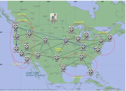
The simulation environment of a hierarchical network configuration is shown in the figure 4 below
Fig 5. Simulation environment of a hierarchical network scenario
Scenario 3: area merge
This scenario depicts IS-IS multihoming configuration.
Normally, Level 1 routers belong to only one area but multihoming is useful for
1. Merging areas,
2. Splitting areas,
3. Renumbering.
This scenario is an example of merging areas.
As be seen in hierarchical network scenario, Level 1 routers which have different area ID cannot form Level 1 adjacency. However, by configuring multiple NETs differentiated only by the area ID, it is possible to merge the areas into a single area.
In this scenario, Portland and San Jose belong to different area but San Jose is configured two NETs with different area ID, i.e. 49.0001 and 49.0002. Area 49.0001 and
[image:7.595.50.253.151.233.2]49.0002 are merged into a single area hence the route from Seattle to San Jose simply goes through Portland.
Fig 6. Simulation environment of area merge scenario
Scenario 4: Failure recovery
This scenario depicts routing behavior in case of node failure/recovery.
The network is same as area merge scenario. Kansas City fails at 1,000 seconds and recovers at 2,000 seconds. Before the failure, traffic from Seattle to DC is splitted over Denver Kansas City link and Denver Dallas link. After the failure, it flows over Denver Dallas link only. After Kansas City recovers, it is splitted over both links again.
Fig 7. Simulation environment of failure recovery scenario
V. Simulation results and findings
Simulation results and findings are provided in this section. Presented figures indicate variations in the update levels of networks tested in different scenario. Four different experiment environments were set up as previously mentioned and their results presented below.
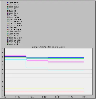
[image:7.595.46.257.309.449.2] [image:7.595.306.510.381.528.2]Fig 8: Simulation result of a simple configuration
Result show no fluctuation in the total number of updates recorded in route tables. This tells us that in a simple configuration, the IS-IS system route table maintains a steady level of update across the network.
hierarchical network: We Illustrated a two-level hierarchical routing and compared the results to non-hierarchical routing tested in the simple configuration scenario above. Results indicate different levels of updates observed in two-level hierarchical routing in contrast to non-hierarchical routing. This indicates there is a clear difference in the level of in route table updates observed in a hierarchical network compared to a non-hierarchical network.
Fig 9: Comparison of a two-level hierarchical routing to a non-hierarchical routing
[image:8.595.47.239.50.209.2]Area merge:We Illustrated an IS-IS feature that allows merging two areas into a single area.
Fig 10: Simulation diagram depicting area merging
Results show significant difference when compared to a hierarchical network as the average levels of routing table updatesreduced across the network. It was also observed that merged areas perform relatively stable and experience stability in the number of updates.
failure recovery:We Illustrated how IS-IS works in case of node failure/recovery.
Fig 11: Simulation diagram depicting failure recovery
[image:8.595.305.509.357.563.2] [image:8.595.47.241.424.587.2]International Journal of Innovative Technology and Exploring Engineering (IJITEE) ISSN: 2278-3075, Volume-8 Issue-8, June 2019
VI. CONCLUSION
After several experiments we have successfully demonstrated various features that can be implemented on an IS-IS system and described how to configure and study the IS-IS model. Results show the robust nature of the IS-IS system and how it can be applied to large networks. One of the most important features of a network is scalability which the IS system has upheld. We have also observed that in case of system failure, the IS-IS system is a protocol that can be relied upon. Also, in terms of network convergence, IS-IS systems show running activity, meaning that the IS-IS system can reinforce itself in case of network break. In conclusion, the IS-IS protocol has also proven to be efficient with little background traffic. Finally, considering routing decision and shortest/fastest path, IS-IS has been observed to transfer packets following the shortest path to destination. For further studies, we recommend comparing the functionality of the IS-IS protocol with existing protocols like EIGRP, RIP and OSPF.
REFERENCES
1. http://www.ciscopress.com/articles/article.asp?p=2180210&seqNum= 7
2. https://www.techopedia.com/definition/25074/interior-gateway-routing-protocol-igrp
3. https://www.cisco.com/c/en/us/support/docs/ip/interior-gateway-routing-protocol-igrp/26825-5.html
4. https://www.cisco.com/c/en/us/support/docs/ip/interior-gateway-routing-protocol-igrp/26825-5.html
5. http://docwiki.cisco.com/wiki/Interior_Gateway_Routing_Protocol //Figure: The Split-Horizon Rule Helps Protect Against Routing Loops
6. https://www.techrepublic.com/article/should-you-use-distance-vector-or-link-state-routing-protocols/
7. https://www.ibm.com/support/knowledgecenter/en/SSLTBW_2.1.0/c om.ibm.zos.v2r1.halz002/rtg_ipv4_dyn_omproute_rip.htm 8.
https://www.cisco.com/c/en/us/support/docs/ip/enhanced-interior-gateway-routing-protocol-eigrp/13669-1.html#intro
9. https://www.techrepublic.com/article/should-you-use-distance-vector-or-link-state-routing-protocols/
10. https://www.cisco.com/c/en/us/support/docs/ip/open-shortest-path-first-ospf/7039-1.html#intro
11. http://www.ciscopress.com/articles/article.asp?p=26850&seqNum=3 12.
https://www.ecse.rpi.edu/Homepages/koushik/shivkuma-teaching/sp2002/ip2002-isis-ospf.pdf
13. http://www.ciscopress.com/articles/article.asp?p=26850&seqNum=4 14. https://www.juniper.net/documentation/en_US/junos/topics/concept/is
-is-routing-overview.html#id-11034328
15. https://content.cisco.com/chapter.sjs?uri=/searchable/chapter/content/ en/us/td/docs/ios-xml/ios/iproute_isis/configuration/xe-16-6/irs-xe-16-6-book/
16. https://www.cisco.com/en/US/tech/tk365/technologies_white_paper0 9186a00800a3e6f.shtml