International Journal of Innovative Technology and Exploring Engineering (IJITEE) ISSN: 2278-3075, Volume-8 Issue-7, May, 2019
Hole Filling Method For Triangular Mesh
Generation
Vandana Agarwal,Naveen Agrawal
Abstract : One of the reasons which results into erroneous triangulated model is the formation of holes during mesh generation. The formation of holes in triangulated models is primarily due to missing data while scanning the object. These holes in the model will result in joining of the triangulated facets in the wrong direction. This further makes large and complicated holes in the model. Most of the work presented in literature identify and fill these holes after the completion of triangulated model which is a time consuming and computationally extensive task. In the present work an algorithm for identifying and filling the hole is proposed which will work along with mesh growing process. The algorithm has been applied to create a triangulated model of a phone receiver. Further, the patch created after filling the hole preserves the shape of original mesh and it blends with the neighboring mesh in a smoother way.
Keywords :Triangular mesh, boundary vertex, hole
I. INTRODUCTION
Construction of a CAD model from a physical part is
done by reverse engineering process. For the same 3D scanners are used to measure data points lying on the surface of a physical part. After this processes like registration, triangulation, segmentation, surface fitting etc. are done to get the CAD model. The model obtained from reverse engineering is refined and improved to obtain an optimal design of the product. If at any stage of the reverse engineering process an erroneous model is created, it makes the further downstream algorithm less effective. One of the sources of such errors is due to formation of holes at triangulation stage. The formation of holes in triangulated models is primarily due to sparse data while scanning the object. These holes in the model result in joining of the triangulated facets in the wrong direction. This further makes large and complicated holes in the model. Most of the work presented in literature [1]-[10] identify and fill these holes after the completion of triangulated model. However, identifying and removing these holes after thegeneration of complete model is a time consuming and computationally extensive task. In the present work an algorithm for identifying and filling the holes is proposed which will work along with mesh growing process. The algorithm has been applied during triangular model construction of a phone receiver.
Revised Manuscript Received on May 10, 2019
Vandana Agarwal, Mechanical Engineering Department, MNNIT,
Allahabad
Naveen Agrawal, Lakshmi Narayan College of Technology & Science
- [LNCTS], Bhopal
II. LITERATURE REVIEW
Most of the literature talks about the hole filling process after the meshing is completed on the whole model. The algorithm for N-sided surface patches satisfying C1 continuity was given by Levin[1]. The algorithm was used to create subdivision surfaces. These subdivision surfaces were connecting the surrounding surface of a hole smoothy. Energy minimization method was utilized by Chui and Lai[2] to fill any number of sides of polygonal holes. A hole filling approach proposed by Curless and Levoy[3] was to interpolate non-sampled surfaces in concave regions of volumetric parts. By this approach water tight models were finally obtained. A radial basis function (RBF) was used to compute an implicit representation by Carr et.al.[4].Filling of holes in unstructured triangular meshes is described by Liepa[5]. In this the shape and density of the neighboring mesh is matched by the newly formed meshes. Jun[6] classified the holes into simple and complex. Simple holes were defined as those which have nonintersecting edges after projection onto 2D plane. The projected hole in the form of polygon is triangulated by 2D Delaunay triangulation. The obtained triangulation was applied on the hole. In the case of complex holes after projection on 2D plane edges of hole were found to be intersecting. Parameters corresponding to intersecting points were computed. Then using these intersecting points the holes were splitted by creating new edges. The process was repeated till the complex holes were transformed to simple holes. Finally the holes were filled. Li, Ye and Zhang[9] reduced the complex holes by splitting them into flatter holes by preserving their detailed features. Then the edge expansion algorithm was applied to fill the remaining complex holes.
III. DETAILS OF ALGORITHM:
3.1 Basic
The model obtained in this way i.e. sharing two triangles at most at their common edge are called manifold model. In the present work it is assumed that construction of manifold model takes place by joining triangles on boundary edges (fig.1) as in region growing process[11]. The region
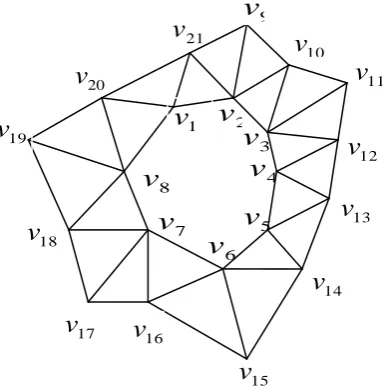
so obtained is called growing region and boundary edges are called boundary of growing region. A hole is a closed loop of boundary vertices (fig.2). Boundary elements (like vertices, edges) of a hole is defined as front.
Fig.1: Triangular mesh showing boundary vertices, non-boundary vertices and joining of triangle on boundary edges
Fig. 2: Two loops of the boundary vertices
3.2 Hole Identification
1. The boundary vertices of growing region(S) are extracted.
2. The loops made by these boundary vertices are found. For example in fig.2 two loops are present namely
v v
1,
2,K
v
8and
v v
9,
10,K
v
21. If more than one loops are present, it indicates the presence of hole. The loop having more numberof vertices is considered to be boundary of growing region and other loops are considered as holes. 3.3 Hole Filling
Following steps are used to fill the holes.
1. The front of the mesh to fill the holes is initialized using the boundary vertices of the
1
v
v
23
v
4
v
13
v
14
v
19
v
11
v
10
v
9
v
8
v
7
v
6
v
5
v
20
v
15
v
17
v
16
v
18
v
12
v
21
v
i
v
j
v
k
v
g
v
f
v
e
v
d
v
hv
av
c
v
bv
Boundary Vertices
Non-boundary Vertices
[image:2.595.110.415.133.349.2] [image:2.595.206.400.414.607.2]International Journal of Innovative Technology and Exploring Engineering (IJITEE) ISSN: 2278-3075, Volume-8 Issue-7, May, 2019
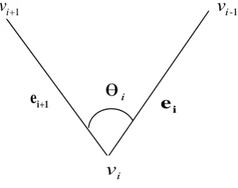
2. The angle
i between the two adjacent boundary edges at each vertex of the front is computed as shown in Fig. 3. [image:3.595.188.360.78.214.2]
Fig. 3: Angle
i between two adjacent edges 3. The vertexv
i having smallest angle
iis selected tostart mesh generation.
4. The new triangles are added on the plane determined by
edges
e
i ande
i+1 using three rules shown in fig. 3 anddescribed below.
Rule- I: When 75o
i vertices
v
i-1andv
i+1are joinedtogether to form new triangles as shown in fig. 4(a).
Rule- II: When 75o i 135o a new vertex
v
newisgenerated (fig. 4(b)) at centre of the circum-circle passing
through
v
i-1,v
i andv
i+1. The new triangles generatedwill be
v v
i-1 new iv
and
v v
i new iv
+1. This will ensurethat the new triangles added are isosceles triangles which is the best possible option to maximise the smallest angle of new triangles. This condition is one of the necessary conditions to get optimal shape of the triangle [12].
Rule III: When 135o
i two new vertices
v
new1 andv
new2are generated as shown in fig. 4(c) and fig. 5. Here the angles
1,
2 and
3 shown in fig.5 are taken as equal to3
i . The new vertices lie on the bisector of edgese
i andi+1
e
respectively. The co-ordinates of new vertexv
new1 arecalculated as the intersection point of the bisector of
e
iand the direction vector making angle
1with edgee
i inthe same plane in which
v
i-1,v
i andv
i+1 lies. Similarlyco-ordinates of
v
new2 are calculated as the intersection pointof the bisector of
e
i+1 and the direction vector making angle3
with edgee
i+1 in the same plane in whichv
i-1,v
iand
v
i+1 lies. This will again ensure that the new triangles t1and t3 are isoscles. Further, length of the edges
e
i+2 andi+3
e
for the triangle t2 will be in proportion to length of theedges
e
iande
i+1. These will ensure the triangles generated to be near to the optimal shape.5. Update the front.
6. Repeat the steps 2 to 5 until the hole region is filled by newly created triangles.
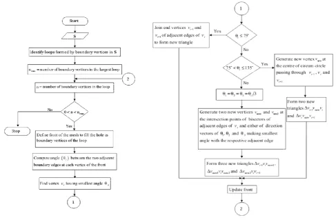
Flow chart of the algorithm is shown in fig. 6.
(a) (b) (c)
Fig. 4: Rules to add new triangles (a) Rule-I when i 75o (b) Rule-II when 75 135
o o
i (c)Rule-III when
135
o
i
1
i-v
i
v
i2
new
v
1
i+
v
v
new1i
v
iv
i-11
i+
v
new
v
i
v
i1
i-v
1
i+
v
i
v
i+1
e
i
e
i1
i+
[image:3.595.61.497.533.703.2]
Fig. 5: Insertion ofnew vertices
v
new1andv
new2 when i 135o
Fig.
6: Flow chart for hole filling
IV. RESULTS & DISCUSSION
The algorithm described in section 3 was applied during triangular model construction of a telephone receiver. The results obtained are shown in figs. 7-10. Holes formed on the triangular mesh model before applying the hole filling algorithm can be seen from the two views given in figs. 7 and 9. Further it can be seen from figs. 8 and 10 that the holes have been removed after applying the hole filling algorithm. Also, it can be seen from figs. 8 and 10 that the new triangles formed have blended with the neighboring mesh in a smooth way. So newly formed triangles represent the object surface well at the location of holes.
1
i-v
i
v
2
new
v
1
i+
v
1
new
v
1
2
3
i
e
i+2
e
i+3
e
i+1
e
t
1t
2t
3International Journal of Innovative Technology and Exploring Engineering (IJITEE) ISSN: 2278-3075, Volume-8 Issue-7, May, 2019
[image:5.595.71.487.93.281.2]Finally it can be said that the proposed algorithm is simple and fills the holes robustly to construct a smooth triangular mesh model .
[image:5.595.119.500.520.684.2]Fig. 7: View of a side face of telephone receiver with holes
Fig. 8: View of a side face of fig.7 without holes
Fig. 9: View showing a large hole on the side of telephone receiver
-10 0 10 20 30 40 50
-50 0 50 100 150 200
-1000 100 Model With Holes
Y-Axis
Z
-A
x
is
X-Axis
-10 0 10 20 30 40 50
-50 0 50 100 150 200
-100 0 100 Model without holes
y-Axis
z
-A
x
is
x
-A
x
is
-10 0 10
20 30
40 -5050 0 50
100
150
200 -60
-50
-40
-30
-20
-10
0
10 Y-Axis
Model With Holes
X-Axis
Z
-A
x
is
Holes
Fig. 10: View showing the removal of the large hole on the side of telephone receiver shown in fig. 9
V. CONCLUSION
In this work hole identification is done with the help of boundary vertices. Three rules are used to generate new vertices for hole filling. As new vertices are in the plane of boundary vertices so it blends nicely to the neighboring shape of the hole. The algorithm has been applied to create a triangulated model of a telephone receiver. The algorithm is able to identify and fill the holes during mesh generation process. Further, the patch created after filling the hole preserves the shape of original mesh. It blends with the neighboring mesh to construct a smooth triangular mesh model.
REFERENCES
1. Levin A., Filling an N-sided hole using combined subdivision schemes; 1999. http://www.math.tau.ac.il(levin/adi/pdf/nsided.pdf) 2. Chui C, Lai M-J.(2000) Filling polygonal holes using C1 cubic
triangular spline patches. Computer Aided Geometry Design, 17;297-307
3. Curless B, Levoy M. A volumetric method for building complex models from range image. Computer Graphics (Proc. SIGGRAPH)
1996; 303-12
4. Carr J, Beatson R, Cherrie J, Mitchell T, Fright W, McCallum B. Reconstruction and representation of 3D objects with radial basis functions. Computer Graphics (Proc. SIGGRAPH) 2001;67-76 5. Liepa P. Filling holes in meshes, Eurographics Symposium on
Geometric Processing 2003 p.200-207
6. Yongtae Jun, (2005) A piecewise hole filling algorithm in reverse engineering, Computer Aided Design 37; 263-270
7. Jiing-Yih Lai, Hou-Chuan Lai, (2006) Repairing triangular meshes for reverse engineering applications. Advances in Engineering Software 37,667-683
8. Wei Zhao, Shuming Gao, Hongwei Lin, (2007) A robust hole filling algorithm for triangular mesh, Visual Comput. DOI 10,1007/s00371-007-0167-y
9. Gen Li, Xiu-Zi Ye, (2008) San-Yuan Zhang, An algorithm for filling complex holes in reverse engineering, Engineering with Computers
24;119-125
10. Jianning Wang, Manuel M. Oliveira, (2007) Filling holes on locally smooth surfaces reconstructed from point clouds, Image and Vision Computing 25; 103-113
11. Chuan-Chu Kuo, Hong-Tzong Yau, (2005) A Delaunay-based
region--10 0 10
20 30 40
50 -50
0 50
100 150
200
-60
-50
-40
-30
-20
-10
0
10 y-Axis
Model without holes
x
-A
x
is
z
-A
x