Page 1 of 12
AC/DC Converter with DC Fault Suppression for Aircraft +/- 270 VDC Distribution
Systems
Michal Sztykiel, Steven Fletcher, Patrick Norman, Stuart Galloway, and Graeme Burt
University of Strathclyde
Abstract
The increasing electrical demand in commercial and military aircraft justifies a growing need for higher voltage DC primary distribution systems. A DC system offers reduced power losses and space savings, which is of major importance for aircraft manufacturers. At present, challenges associated with DC systems include reliable fast acting short circuit protection. Solid State Contactors (SSC) have gained wide acceptance in traditional 28 VDC secondary systems for DC fault interruption. However, the reliable operation at higher operating voltages and currents requires further technology maturation.
This paper examines a supporting method to SSC for more reliable fault mitigation by investigating bidirectional AC/DC converter topology with DC fault current blocking capability. Replacement of semiconductor switches with full bridge cells allows instant reversal of voltage polarities to limit rapid capacitor discharge and machine inductive currents. Demonstration of this capability is realized by tracking DC fault currents in time-domain simulations of a ±270 VDC converter dynamic model built in MATLAB-Simulink. Simulation results have shown that the modified power converter topology provides a fast response to DC faults and it can be considered as a back-up to SSCs in clearing faults in ±270 VDC distribution systems.
Introduction
Increasing role of electrical energy in aircraft designs has resulted in replacing traditional mechanical, hydraulic and pneumatic transmission systems with an electrical equivalent.
An idea for aircraft electrification was first applied to military designs in order to reduce weight and maintenance costs [1]. Throughout years, this concept has evolved into trend known as the More Electric Aircraft (MEA) [2], where research efforts are made to optimize electrical distribution systems by integrating them with the existing technologies from areas of power electronics, data communication and microprocessors [3].
One of the major consequences of adapting the MEA is that electrical power consumption needs to be significantly increased. In large aircraft designs, the increased power demand introduced by new functions of the electrical system has become a challenge in terms of possible space savings and power losses. An increase of nominal
power results in larger currents in primary distribution network, which must be carried by thicker and heavier wires [4].
Moreover, large currents generate higher power losses that dissipate into heat, thus imposing stricter requirements on the existing cooling systems as well as reduced fuel efficiency [5]. In order to mitigate issues related to the excessive load currents, existing network architectures are being investigated, which allow operation at higher voltages and provide further space and fuel savings.
[image:1.612.324.575.380.507.2]Figure 1 illustrates the adoption of common aircraft electrical power distribution methods since the 1950s. It can be seen that, ±270 VDC networks are of growing interest to aircraft manufacturers as they provide some important advantages over the other primary distribution networks.
Figure 1.Evolution of aircraft electrical systems [2].
In comparison to 270 VDC systems, utilising an increased ±270 V voltage allows further weight reductions in cabling and smaller cooling system equipment [6]. DC architectures also eliminate issues of their AC equivalents related to reactive currents [7-8] and allow parallel asynchronous operation of the electrical machines with reduced number of power electronic interfaces [9].
Whilst these potential advantages exist, a number of technical challenges limit the development of future ±270 VDC networks. The most significant issues are associated with DC fault interruption, protection and safety [10-12]. Therefore, there is a need to develop effective solutions that could be utilized in order to mitigate these issues and to provide reliable operation of the ±270 VDC networks for future aircraft primary distribution systems.
Page 2 of 12
systems. A DC fault can be directly mitigated by means of the available high voltage DC contactor technologies: electromechanical, hybrid and solid state switches [13]. It is possible to significantly shorten the time for fault isolation using solid state breakers (with potential associated benefits of reduced fault energy and minimized heat dissipated during the short circuit period) [14, 15], however the failure modes of these devices in harsh operating environments are not well understood For example the solid state contactor may become shorted during the DC fault [16], resulting in lack of DC protection for the primary system.
The paper will present a supporting method for reliable DC fault mitigation embedded in a modified bidirectional AC/DC converter topology. The key difference using this approach is that the proposed DC fault suppression mechanism is based on reversing the polarity of the capacitor voltages within the converter itself rather than injecting high resistance or interrupting electrical arc. This fault suppression mechanism provides fast fault clearing times with low voltage peaks across the semiconductor devices, as the contributing capacitors successfully limit the voltage rate of rise. The disadvantage includes increased number of components required for each phase leg, which results in larger footprint and increased conduction losses of a converter.
The proposed converter topology is compared with conventional six-switch Voltage Source Converter (VSC) with and without solid state DC breaker. The comparison is realized by simulation of time-domain dynamic models built in MATLAB-Simulink, where each converter is fed by 120 kVA Permanent Magnet Synchronous Generator (PMSG).
The simulation results show that proposed converter system successfully mitigates DC fault currents with clearing times in range of the solid state devices and low overvoltage transients. Finally, the paper concludes that the proposed DC protection mechanism can be applied for the critical parts of the ±270 VDC network, where reliable and fast DC fault interruption becomes crucial for system performance.
Review of Existing Methods for DC Fault
Suppression
Fault Types in AC/DC Converter Interfaced Systems
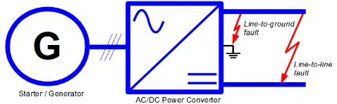
DC bus faults may appear either between positive and negative poles (line-to-line) or between single pole and solid grounded common-mode point (line-to-ground), as presented on Figure 2. Line-to-line faults may induce at:
1. DC bus sections, where positive and negative poles of each section are located in close proximity
2. Power converter DC terminals, due to internal switch commutation failures.
[image:2.612.333.572.38.112.2]Line-to-ground faults may often originate at DC cable sections due to cable insulation deterioration and breakdown, which is typically caused by harsh environment, electrical stresses and partial discharge effect at high altitudes.
Figure 2. DC fault types: line-to-line and line-to-ground.
This paper assumes that the resulting DC fault current
C gen
fault i i
i (1)
is made of two individual contributions that include AC machine load current igen and DC link capacitor discharge current iC. Current
commutation loops for each contribution during line-to-line faults are illustrated in Figure 3. The AC machine is interconnected to the DC grid via an active bridge rectifier. The six switch VSC is selected for active bridge circuitry due to its simplicity and wide usage as a standard AC/DC interface in electrical machines [11].
During the short circuit period, active switches T1-6 can be immediately switched off to realise block mode for overload protection. However, antiparallel diodes cannot be disconnected and therefore provide a commutation path for machine-side currents. As a result, these currents contribute to the fault current until the protection device opens the circuit path either on AC-side (3-pole breaker) or DC-side.
Figure 3. DC Line-to-line fault contributions from AC machine (iGEN) and DC
capacitors (iC).
DC link capacitor discharging currents are caused by the capacitor short circuit. For line-to-line faults, both upper and lower capacitors are shorted at the same time, whereas in line-to-ground faults only the single capacitor is effectively shorted. The magnitude of the DC link capacitor discharge current is related to:
DC capacitor impedance, represented by the capacitance and equivalent series resistance (ESR).
DC cable resistance and inductance
[image:2.612.327.573.353.502.2]Page 3 of 12
DC capacitor voltage
Reference [14] presents analytical expressions to quantify capacitor discharge current from these variables.
In order to minimize power losses and voltage drop, ESRs need to be as small as possible. As a result, low damping factor often results in very high and short current peak being induced immediately after fault occurrence [14]. Dissipation of the short circuit energy within this short period may require increased momentary ratings of the DC link capacitors, interconnected cables and converter devices.
[image:3.612.325.576.261.336.2]One of the options for clearing the DC fault is to isolate interconnected AC-sides through front-end AC breakers [25]. Another solution might be usage of current limiting DC fuses [26]. However, in future aircraft systems with a common DC bus, the described methods may however not provide satisfactory performance in terms of safety and stability to re-energize existing loads, sources and capacitors after isolating the faulted segment. Hence, for more extensive DC systems there is a prerequisite for fast acting fault suppression method with reliable performance and ability to restore electrical power as quickly as possible. Figure 4 illustrates possible methods for DC fault suppression incorporating DC breaker designs and improved AC/DC converter designs. Existing DC breaker technologies include: electromechanical, hybrid and solid state devices, whereas fault current limiting AC/DC converter topologies can be current source (CSC) or alternative voltage source (VSC).
Figure 4. Methods for DC fault suppression: DC breakers and fault-limiting converters.
Apart from the described DC fault suppression methods, various fault current limiting methods are described in the literature [27]. Fault current limiters (FCL) provide a means of reducing fault current to be reduced to a selected level rather than dictated by the network. This can have number of advantages such as reducing the required circuit breaker ratings and stress on the system components during faults. However a full review of fault current limiting devices is beyond the scope of this paper, with the focus instead on fault clearance technologies (without the need for FCL technologies).
Electromechanical Breakers
Conventional DC breakers (illustrated in Figure 5a) use electromechanical contactors to galvanically isolate the circuit and generate an adequate electrical arc during the circuit interruption.
This arc-based approach requires methods and technologies for optimal arc generation and quenching.
The arc itself provides two essential functions [15, 17]:
Gradual voltage built-up across the breaker terminals - to compensate the voltage drop across the fault loop inductances and therefore limit the rate of change of outrush currents. Short circuit energy dissipation from circuit inductive
elements - to dissipate energy from these inductances in a location of the installed breaker. In this manner, the energy can be trapped and burned in safe and controllable manner.
[image:3.612.36.289.352.499.2]Arc-based electromechanical DC breakers can be considered the most mature in terms of performance amongst the devices considered in this paper, and are commercially utilized in many industrial applications, e.g. traction, marine and aerospace [18]. Achieved technology maturity for these devices has allowed a significant price reduction for the wide range of power ratings available on the market.
Figure 5.DC breakers: a) electromechanical; b) solid state; c) hybrid [16].
However, relatively long interruption times of these devices can result in significant amount of heat being dissipated across the system components, thus increasing their momentary ratings and ultimately, the overall size and cost of the electrical system. In addition, the lifetime of the electromechanical breakers is reduced by deterioration and erosion of the contactor materials, which are exposed to large amounts of heat from the electrical arc ignition.
Solid State Breakers
Solid-state contactors (as illustrated in Figure 5b) are made of power electronic switching devices, which are used specifically to interrupt DC fault currents by means of gate driver control. The semiconductor layered material provides a large resistance according to the gate driver signal. Therefore, no electrical arc is required to provide voltage drop across the semiconductor terminals [15, 17].
In order to dissipate the short circuit energy from circuit inductive elements, semiconductors are paralleled either with snubber RC passive circuits or surge arresters with non-linear current-voltage characteristics. These devices perform an overvoltage protection function against voltage spikes being induced while isolating the DC circuit.
Solid state devices are capable of very fast fault interruption, since voltage drop across the device is only by operating time of the fault detection scheme and surge arrestor characteristics. In addition, the absence of electrical arc eliminates maintenance issues normally associated with electromechanical breakers.
Page 4 of 12
available for higher ratings, they have not yet been widely utilised in commercial DC breaker application [17]. This is primarily due to the natural characteristics of semiconductors, which can become prohibitive in high power systems with large load currents. These characteristics are:
1. High on-state conduction losses. Under normal operation, SSCs exhibit higher conduction losses than electromechanical breakers. This is the result of replacing conductive contactors with semi-conductive layers.
2. New failure mechanisms. Detailed investigation is required on semiconductor failure mechanisms. These mechanisms have not yet been well defined and understood in a harsh aircraft environment and may eventually lead to premature failures and unexpected post-fault behaviour of the device (explosion, short circuit, etc.).
Hybrid Breakers
[image:4.612.29.296.336.657.2]Hybrid breakers are a parallel combination of electromechanical and solid-state contactors (as illustrated in Figure 5c). With the coordinated operation of both elements it is possible to reduce both the maintenance issues associated with electromechanical devices, as well as the high power losses associated with solid state switches.
Table 1.Comparison between DC breaker designs for ±270 systems [17].
Breaker Electromechanical Solid State Hybrid
TRL 9 4-5 4-5
Key
Components Copper contacts
Power semiconductors
Power semiconductors and
copper contacts
Breaking
Time Tens of milliseconds Few microseconds microseconds Tens of
Galvanic
Isolation Yes No Yes
Conduction
Losses Low High Low
Advantages
Mature
technology.
Wide range of
ratings available
Low conduction
losses.
Very fast breaking time.
Arc-less breaking mechanism.
Fast breaking time.
Reduced
electrical arcs.
Low conduction
losses.
Disadvantages
Long breaking
time.
Limited lifetime due to electrical arcs.
Narrow range of
ratings available.
High conduction
losses.
Unreliable failure behaviour.
Low TRL.
Complex design.
Under normal operation, the solid state device is opened and the main electromechanical switch is closed. Current does not flow through the semiconductor element, which significantly reduces the on-state conduction losses.
After fault has been detected, the semiconductor switch closes rapidly and the electromechanical switch reopens. This operation forces current to commutate through the closed solid-state switch, which reduces the energy of electrical arc and allows a faster interruption time. Finally, the solid-state breaker opens to interrupt the current and clear the fault path.
Similar to solid state devices, hybrid breakers are in still a relatively immature technology. As a result, they are less widely available in commercial products for high power applications. Table 1 summarizes and compares main features of the described devices.
Current Source Converters
An alternative to fully rated DC breaker designs is the DC fault protection function embedded within AC/DC converter circuitry. Current source converters (CSC) (as illustrated in Figure 6) provide an inherent DC fault suppression capability since they do not require large DC link capacitors that discharge during the short circuit. On the contrary to DC voltage, the DC current is kept constant using a large DC link inductor, which effectively limits current rate of rise in the event of a fault.
During normal operation, CSCs exhibit typically lower power losses than VSCs [28]. This originates from a low switching frequency and semiconductor device characteristics that are associated with CSC topologies.
CSCs normally require large DC breakers to isolate the circuit whenever it is required. As more energy is stored in the DC link inductor, it needs to be dissipated either in the form of an electrical arc, or in the form of a transient overvoltage.
Figure 6. DC line-to-line fault loop in current source converter topologies.
Finally, a relatively large physical footprint is often associated with CSCs due to the high torque ripple caused by low switching frequencies of the semiconductor switches and poor input power factor. Additional AC-side inductive filters are often required to reduce such ripple, which further increases the overall size and weight of the system (DC link inductors already need to be larger than equivalent DC link capacitors for VSCs). Table 2 summarizes and compares main features of the CSCs with VSCs.
[image:4.612.328.574.389.550.2]Page 5 of 12
DC link capacitors, the converter circuitry considered in this paper has been modified to provide a fast and reliable DC fault protection mechanism.
[image:5.612.328.575.37.208.2]This paper presents the operating principles of such a mechanism called voltage polarity reversal, which is achieved by bidirectional DC link voltage control.
Table 2.Comparison between CSC and VSC [28].
Converter CSC VSC
Key
Component Thyristor (IGCT, GTO) Transistor (IGBT, MOSFET)
Power losses Low High
Power quality Low High
DC-side
inductors Large Small
DC-side
capacitors Small Large
Advantages
Small and controllable di/dt of DC fault current.
Durable semiconductor
switches.
Low power losses.
Low filtering requirements.
Four-quadrant power
control.
Fast control response during transients.
Disadvantages
High filtering requirements.
No decoupled reactive power control.
Large electrical arcs induced during DC open circuit
Excessive DC capacitor
discharge currents during DC faults.
No controllability during DC short circuit.
Relatively high power losses.
Voltage Source Converter Topology with DC
Fault Suppression
Operating Principles
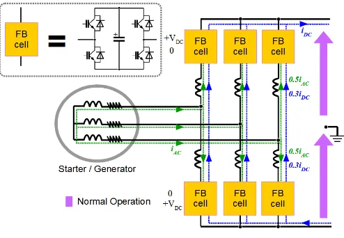
Figure 7 presents a modified VSC topology whose dynamic performance will be studied later in this paper. In comparison to the standard six-switch converter from Figure 3, it replaces each power semiconductor switch with a full bridge (FB) modular cell and eliminates common DC link capacitors.
The described topology originates from [20] and is available in marine and power systems applications [21, 22], where a high voltage output is achieved by cascading full-bridge cells according to the DC voltage nominal rating. In aircraft electrical systems, ±270 VDC level allows utilization of just a single cell per arm.
The cell illustrated in Figure 8 consists of four semiconductor switches and a DC link capacitor. As a result, the DC link voltage is decentralized and distributed within arms rather than having common DC link between upper and lower poles.
Figure 7.VSC full bridge cell converter: operating principles.
[image:5.612.36.290.138.468.2]Such a circuit arrangement allows flexible control of the DC link capacitor energy individually in each arm by applying a specific switching pattern.
Figure 8.VSC full bridge cell converter: cell commutation states.
Possible states and commutation paths illustrated in Figure 8 show that each cell can be represented as a controllable DC voltage source with 3 states:
Positive DC voltage (+VDC),
Short circuit (0)
Negative DC voltage (–VDC).
Short circuit mode includes single redundancy as either switching on both upper or both lower switched semiconductors will by-pass the DC link capacitor.
Under normal operation, upper and lower arm cells in each phase are PWM switched in a complementary fashion between positive voltage mode and short circuit mode. As a result, DC voltage is continuously clamped either by the upper cell arm or lower cell arm. AC-side phase currents are split in half between upper and lower arms in order to recharge phase arm capacitors, which normally provide a controlled discharge current iARM to the DC circuit according to
3 2
DC AC ARM
i i
[image:5.612.328.572.270.423.2]Page 6 of 12
By decoupling AC and DC currents it is possible to independently control both circuits and further enhance the system dynamic performance through individual cell controllers for each phase.
Voltage Polarity Reversal
[image:6.612.325.575.109.392.2]Inherent DC fault suppression is provided by a means of the negative voltage mode. When a DC short circuit occurs, the upper arm cells can be instantly switched to a positive voltage mode whereas the lower arm cells are switched to a negative voltage mode (or vice versa). As shown in Figure 9, the resulting DC link voltage is zero as the upper arm capacitor voltages are compensated by their lower arm equivalents.
Figure 9.VSC full bridge cell converter: DC fault suppression mechanism.
The inverse sequence in the voltage polarity reversal also acts as a back-up protection during the redundant operation where one of the semiconductors fails in FB cell. On the contrary to solid state DC breakers – the short circuit failure of a single switch in each FB cell would not impact the protection function of the converter.
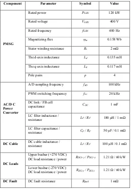
In order to validate the described DC fault protection function, the dynamic time-domain models have been developed in MATLAB/Simulink, which include a Permanent Magnet Synchronous Generator (PMSG) and an AC/DC Power Converter.
Dynamic Modelling
Permanent Magnet Generator
The schematic representation of the PMSG model is shown in Figure 10. The PMSG is modelled as a 3-phase current source in the dq rotating reference frame as presented in [23]. Key characteristics are
sq q e sd s sd sd
d i v Ri Li
dt d
L (4)
and m e sd d e sq s sq sq
q i v Ri Li
dt d
L (5)
where vsd and vsq are the measured instantaneous stator voltages, Rsis
the stator winding resistance, Lsd and Lsq are the resulting stator
inductances (leakage and magnetizing), ωe is the generator rotational
speed and ψm is the permanent magnet flux linkage.
The generator rotor speed is set externally, with the front-end AC/DC converter unit responsible for controlling the machine active (PGEN)
and reactive (QGEN) power according to the following relationships
sq sq sd sd
GEN v i v i
P , (6)
sq sd sd sq
GEN v i v i
Q . (7)
Figure 10. Dynamic modelling of the PMSG: a) dq reference frame; b) AC current source.
AC/DC Power Converter
The VSC model is split into 5 functional parts, as illustrated in Figure 11. The control architecture includes an outer DC voltage control loop with associated PI controller and an inner AC current control in the dq rotating reference frame. The AC current control is realized according to d F d F q F e sd
d i Ri
dt d L i L v
e , (8)
q F q F d F e sq
q i R i
dt d L i L v
e (9)
where edq are the output converter voltage dq references, LF is filter
inductance and RF is filter parasitic resistance.
The sampled voltage reference signals are converted to the ABC frame via a Park Transform and sent to the PWM modulator block to determine whether cells should be switched to short circuit (signal “0”) or positive voltage (signal “1”) mode. The PWM is triangular carrier-based technique switched at a frequency fSW with
[image:6.612.41.284.176.355.2]Page 7 of 12
Figure 11. Dynamic model of AC/DC converter control architecture.
Finally, a DC protection unit (illustrated in Figure 12) is included which activates primary or back-up DC protection following a fault occurrence by changing the mode of the single arm cells from positive to negative voltage (signal “-1”). During this protection mode operation, the input signals from the PWM block are simply by-passed. For each mode, a table of states for the four semiconductor switches T1-4 is implemented in accordance with Figure 8.
Figure 12.Dynamic model of FB cell converter with DC fault protection.
Simulation Study
[image:7.612.39.286.575.663.2]System Description
Figure 13 shows the analysed ±270 VDC systems in the MATLAB-Simulink environment. It includes the PMSG, LC filter, AC/DC converter circuitry, and DC resistive load. The commutation angle Ɵ
is directly obtained from machine model for the converter dq control.
Figure 13.MATLAB-Simulink dynamic model of systems A, B and C.
The performance of the proposed converter circuitry is validated and compared with equivalent systems A, B and C:
1. System A - consists only of conventional six-switch converter. 2. System B - consists of conventional six-switch converter
equipped with 2-pole ideal solid-state DC breaker from Figure 5b (without surge arresters).
A 2-pole breaker is installed on upper and lower DC bus bars to avoid line-to-ground voltage unbalance during the line-to-line DC fault.
3. System C - consists of the proposed FB cell converter with embedded DC fault protection mechanism.
The AC/DC converter control architecture for systems A, B and C is identical and is illustrated in Figure 11.
Table 3 lists the parameter values used for populating the system. The LC filter (consisting of components LF and CF) has been sized to
minimize current harmonic ripples, according to [12]. DC link capacitors CDC are sized to maintain DC voltage peak-to-peak ripple
below 3% [12]. The switching frequency fSW is 20 kHz according to
[22], which is sufficient to meet limits of transient characteristics specified in [12] for the equivalent 270 VDC system.
Normal Operation
Figure 14 shows simulation results of the DC link voltage vDCduring
system start-up for the FB cell converter. In this figure, the calculated instantaneous AC power PGEN from (6) is compared with DC power
DC DC
DC v i
P (10)
and mechanical power
p T
P e
e m
(11)
where electromagnetic torque is
msq d q sdsq
e p i L L i i
T 2
1
Page 8 of 12
Table 3.Parameter specification for MATLAB/Simulink dynamic modelling.
Component Parameter Symbol Value
PMSG
Rated power PGEN 120 kW
Rated voltage VGEN 400 V
Rated frequency fGEN 400 Hz
Magnetizing flux ψm 0.158 Wb
Stator winding resistance Rs 2 mΩ
The d-axis inductance Ld 0.135 mH
The q-axis inductance Lq 0.117 mH
Pole pairs p 4
AC/D C Power Converter
A/D sampling frequency fAD 100 kHz
PWM switching frequency fsw 20 kHz
DC link / FB cell
capacitance CDC 1 mF
LC filter inductance /
resistance LF / RF 180 μH / 1 mΩ
LC filter capacitance /
resistance CF / RF 50 μF / 0.1 mΩ
DC Cable DC cable inductance / resistance LF / RF 100 μH / 0.1 mΩ
DC Loads
Upper busbar (+270 VDC)
DC load resistance / power RDC(+) / PDC(+) 1.21 Ω / 60 kW
Lower busbar (-270 VDC)
DC load resistance / power RDC(-) / PDC(-) 1.21 Ω / 60 kW
DC Fault DC fault resistance Rfault 1 mΩ
The reference signal for the reactive current iq* is set to control the
generator operating voltage VGEN during the variations of load RDC or
speed ωe.
Figure 14. DC voltage vDC(t) (upper) and AC/DC/mechanical power P(t)
characteristics during system start-up.
In order to evaluate the dynamics of the modelled system, a DC voltage reference step response VDC* is implemented. As illustrated
[image:8.612.35.291.54.425.2]in Figure 15, it is seen that good dynamic performance can be achieved with the proposed control architecture.
Figure 15.DC voltage vDC(t) (upper), AC voltages (middle) and AC currents
(bottom) characteristics during vDCstep response.
The measured DC voltage tracks the reference well providing a fast response and minimal oscillations. A similarly good response is obtained for measured AC currents and voltages.
Fault Operation
The control architecture utilised is consistent for Systems A, B and C. For Systems A and B, whilst the six-switch converter topology is unable to block the dc fault currents, it is still switched to block mode, where all active switches are turned off to avoid possible damage to the active switches made by excessive machine-side fault currents. Table 4 presents the fault timing sequence used in this study. The fault is applied at 0.1 s by energizing a switch from Figure 12.
In each case, it is assumed that the protection relay detects the fault and activates DC fault protection mechanism for systems A, B and C. According to [29], gate driver circuitry requires 10 μs delay to issue a fault signal by monitoring saturation (collector) voltage of the IGBT. In system A, only block mode is activated. In system B, block mode is activated and tripping signal is sent to solid state breaker for DC fault clearing. In system C, opposite voltage modes are activated for upper and lower arm cells.
Table 4.Fault timing sequence for systems A, B and C.
Event Time Action
Normal operation → 0.1 s
Systems A, B and C operate at nominal loading conditions
DC fault 0.1 s
DC fault protection
mechanism activates + 10 μs
System A: all active switches turn OFF.
System B: all active switches turn OFF and DC breaker trips.
[image:8.612.40.286.472.617.2] [image:8.612.325.575.538.673.2]Page 9 of 12
[image:9.612.326.575.62.213.2]Line-to-Line Fault
Figure 16 shows the line-to-line busbar fault current characteristics of systems A, B and C under line-to-line fault conditions.
After 0.1 s of simulation time, a DC short circuit results in the rapid capacitor discharge of the filter capacitor in all the analysed systems. After 10 μs, DC fault protection mechanism activates individually for each converter. An absence of DC fault suppression in system A results in an excessive capacitor discharge current iC.
Figure 16. DC line-to-line fault current [A] characteristics vs. time [s] for systems A, B and C: a) ms range; b) μs range.
In the case of systems B and C, the fault protection mechanisms activate and significantly limit the fault current, thus preventing further discharge of the capacitor. In system B, the fault path is immediately broken by means of injecting high resistance to the current commutation path and clamping it with anti-parallel diodes in both directions.
Activation of the negative voltage mode in system C results in rapid voltage polarity reversal in corresponding arms of the converter, which provides the effective zero voltage across the DC link terminals. On the contrary to system B, the fault path current is not completely cleared and a small leakage circulating current flows below 10 A, until its energy dissipates in resistive circuit elements. Even though the fault current rise is stopped, the current does not break instantly, but rather declines with a 1 ms time constant. Such behaviour is the consequence of having inductive arm filters, which are in series with the FB cell capacitors in a fault loop and therefore limit the current change after voltage polarity reversal.
Figure 17 shows line-to-ground voltage plots for each system during the line-to-line fault. The positive and negative busbar voltages are of
opposite polarity for all of the studied DC fault protection mechanisms.
Figure 17. Positive-to-ground (top) and ground-to-negative (bottom) polarity voltage characteristics vs. time [s] for systems A, B and C.
In system B, the mounting of 1-pole SSC only on a single busbar results in voltage unbalance between the DC loads. As a consequence, the polarity of a positive voltage becomes negative and both capacitors discharge in the opposite directions. In order to prevent this voltage polarity reversal, an additional SSC must be installed on the negative DC busbar (2-pole breaker). Alternatively, deactivation of the block mode allows the mitigation of voltage polarity reversal on condition of having an over-rated six-switch converter.
Line-to-Ground Fault
Figures 18 and 19 show accordingly the positive and the negative line-to-ground fault current characteristics of systems A, B and C under solid line-to-ground fault conditions.
[image:9.612.39.286.147.450.2]Page 10 of 12
Figure 19. Negative voltage busbar line-to-ground fault current [A] characteristics vs. time [s] for systems A, B and C: a) ms range; b) μs range.
After 0.1 s of a simulation time, the positive line-to-ground short circuit results in capacitor underdamped discharge current [14]. The higher oscillations on the positive busbar appear due to the lower equivalent circuit resistance, which consequently reduces the circuit damping factor.
After 20 ms, the oscillations are effectively damped and the machine-side load current is rectified through the passive diode bridge. Since the positive voltage DC loads (+ 270VDC) are solid grounded, they are by-passed and an increased current flows through the negative voltage DC loads (- 270 VDC).
In a similar manner to line-to-line fault behaviour, systems B and C provide proper DC fault protection either by breaking the current or reversing polarity of FB cells. The fault current characteristic in system B equipped with a 2-pole breaker is identical with the previous case. In system C, fault current peaks are reduced by 15% and no drift appears after 1 ms, as there is no effective connection between the DC terminals with only upper arm inductors contributing to the fault characteristic.
Figure 20 shows line-to-ground voltage plots for each system during the line-to-ground fault. In each analysed system, the voltage on the positive busbar is effectively zero.
[image:10.612.325.574.34.184.2]In system A, a negative DC voltage is increased by 30% by means of excessive machine-side load currents, which are the result of the reduced DC load. In system B equipped with 2-pole breaker, the negative voltage is identical to voltage on the positive busbar. In system B equipped with a 1-pole breaker located on positive busbar, a voltage slowly decreases after 20 ms. In system C, negative voltage reaches 10% peak prior to activation of fault protection mechanism. When the voltage polarity reversal scheme is applied, the negative voltage decreases to 0 after 0.5 ms.
Figure 20. Positive-to-ground (top) and ground-to-negative (bottom) polarity voltage characteristics vs. time [s] for systems A, B and C.
Summary
The reliable and fast DC fault mitigation technique is of major importance for future ±270 DC networks. High voltage distribution enables potential weight and space savings, which is critical for future MEA designs.
This paper has provided an overview and comparison of existing methods for DC fault suppression which might be adapted in aerospace industry. The methods are divided into two subcategories: DC breaker designs and AC/DC converter topologies that offer embedded DC fault protection. Among DC breakers, solid state designs offer the advantage of fast breaking times. However, high power rated breakers require technology maturity for reliable protection of the critical parts in the aircraft system.
In order to further increase reliable DC fault protection, the paper also investigates DC fault suppression mechanism of an alternative VSC topology, which is adapted from high voltage power systems and modified according to voltage ratings of MEA systems. Instead of single semiconductor switches, the topology utilizes modular FB cells, which can be used to independently control each phase of the machine (thus providing operation with reduced power in case of machine-side AC fault). The proposed topology has been modelled in MATLAB-Simulink to provide accurate dynamic response during faults and to validate proposed DC fault suppression mechanism, which is achieved through voltage polarity reversal.
The results have shown that the proposed converter properly and quickly mitigates fault current with a competitive performance to conventional VSC equipped with solid state DC breaker. As a result, the examined mechanism can be considered as a support to existing DC breaker technologies.
The lifetime period of the FB cell converter is extended by means of the existing redundancies in each cell (potentially improving the availability and dispatchability of aircraft systems containing these converters). This inherent redundancy also overcomes issues with the failure modes of standard SSCB designs.
[image:10.612.39.286.35.319.2]Page 11 of 12
The increased number of components results in a large footprint, dictated mostly by size of the FB capacitors. During steady state operation, the load current will always flow through a pair of semiconductors (as illustrated in Figure 8), which doubles conduction losses compared to conventional six-switch VSCs. However, a variety of different switching combinations allow modification of the switching pattern to minimize losses during transient states and balance the amount of dissipated power between the devices. This may ultimately increase lifetime of the semiconductor switches due to reduced temperature variations.
Given these characteristics, the analyzed FB cell topology seems best suited to critical parts of the system where the reliable operation is of the highest concern, offset by an increased volume and steady state losses. For this style of application, further work is required to quantitatively compare the weight, size and efficiency of this topology with that of a similarly redundant six-switch VSC and SSCB design.
References
1. Eicke, J.M., Hodge, E.S., Price, W.D, Ravaris, P.A, et al., “Advanced Power System Study,” Technical Report CDRL 3402, Air Force Contract F33657-84-C-0247, Wright Patterson Air Force Base, USA, 1992.
2. Moir, I., Seabridge, A., “Aircraft Systems: Mechanical, Electrical and Avionics Subsystems Integration,” (Aerospace Series, Wiley, 2008), pp 182, ISBN: 0470770945.
3. Wyatt, D., Tooley, M., “Aircraft Electrical and Electronic Systems: Principles, Maintenance and Operation,” (Butterworth-Heinemann, Elsevier, 2009), ISBN: 9780750686952.
4. Brombach, J., Schroter, T., Lucken, A., and Schulz, D., "Optimizing the Weight of an Aircraft Power Supply System Through a +/- 270 VDC Main Voltage,"
Electrical Review, No. 1a/2012, pp. 47-50, 2012.
5. Fletcher, S., Norman, P., Galloway, S., and Burt, G., "Impact of Engine Certification Standards on the Design Requirements of More-Electric Engine Electrical System Architectures," SAE Int. J. Aerosp. 7(1):24-34, 2014, doi:10.4271/2014-01-2119.
6. Furmanczyk, K. and Stefanich, M., "Demonstration of Very High Power Airborne AC to DC Converter," SAE Technical Paper 2004-01-3210, 2004, doi:10.4271/2004-01-3210.
7. Purellku, I., Lucken, A., Brombach, J., Nya, B., et al., “Optimization of the Energy-Supply-Structure of Modern Aircraft by Using Conventional Power System Technologies,” CIRED 2011, No. 0973, Germany, 2011.
8. Starke, M., Tolbert, L., Ozpineci, B., "AC vs. DC distribution: A loss comparison," T&D. IEEE/PES 2008, Vol. 1, No. 7, pp. 21-24, USA, 2008, doi: 10.1109/TDC.2008.4517256.
9. Zheng, X., Gao, F., and Bozhko, S., "Stability Study of DC Electric Power System with Paralleled Generators for More-Electric Aircraft," SAE Technical Paper 2014-01-2114, 2014, doi:10.4271/2014-01-2114.
10. SAE AE-7C Systems Committee, "Electrical Power, 270 V Dc, Aircraft, Characteristics and Utilization," SAE Standard AS1831A, Rev. Jul. 2010.
11. Fletcher, S., Norman, P., Galloway, S., and Burt, G., "Impact of Converter Interface Type on the Protection Requirements for DC Aircraft Power Systems," SAE Int. J. Aerosp. 5(2):532-540, 2012, doi:10.4271/2012-01-2224.
12. Department of Defense Interface Standard, "Aircraft Electric Power Characteristics," MIL Standard 704F, Rev. Oct. 2013.
13. Liu, Z., Fuller, R., and Pearson, W., "SSPC Technologies for Aircraft High Voltage DC Power Distribution Applications," SAE Technical Paper 2012-01-2213, 2012, doi:10.4271/2012-01-2213.
14. Fletcher, S., Norman, P., Galloway, S., Crolla, P., et al., "Optimizing the Roles of Unit and Non-unit Protection Methods Within DC Microgrids," IEEE Smart Grid, Vol.3, No.4, pp.2079-2087, 2012, doi: 10.1109/TSG.2012.2198499.
15. Fletcher, S., Norman, P., Galloway, S., Burt, G., "Determination of protection system requirements for DC unmanned aerial vehicle electrical power networks for enhanced capability and survivability," IET Electr. Syst. Transp., 2011, Vol. 1, Iss. 4, pp. 137–147. doi: 10.1049/iet-est.2010.0070.
16. Kiep, A., Puerschel, M., Spielman, C., "Understanding Short Circuit Events and Power Semiconductors," SAE Technical Paper 2015-01-0269, 2015.
17. Wang, Y., "Review of DC Circuit Breakers for Submarine Applications," Defense
Science Technology Organisation, Technical Note DSTO-TN-1174,
http://www.dsto.defence.gov.au/publication, accessed Mar. 2012.
18. Bartosik, M., Lasota, R., Wojcik, F., "Modern dc circuit breakers," Rail Transport Technique: 25-32, Sep. 2006.
19. Franck, C., "HVDC Circuit Breakers: A Review Identifying Future Research Needs," IEEE Trans.Power Delivery, Vol.26, No.2, pp. 998-1007, 2011, doi: 10.1109/TPWRD.2010.2095889.
20. Baker; R.H., Bannister, L.H., "Electric Power Converter," U.S. Patent 3,867,643 A, February 18, 1975.
21. Staudt, V. Jager, M.K., Rothstein, A., Steimel, A., et al., "Short-circuit protection in DC ship grids based on mmc with full-bridge modules," presented at ESARS 2015, Germany, March 3-5, 2015.
22. Reynolds, M., "TresAmigassuper station - Large scale application of VSC back-to-back technology," PES 2012 , Vol. 1, No. 5, pp.7-10, USA, 2012, doi: 10.1109/TDC.2012.6281708.
23. Rosyadi, M., Muyeen, S., Takahashi, R., and Tamura, J., "A Design Fuzzy Logic Controller for a Permanent Magnet Wind Generator to Enhance the Dynamic Stability of Wind Farms." Appl. Sci. 2, No. 4: 780-800, 2012, doi: 10.3390/app2040780.
24. Burgos, R., Gang,C., Wang, F., Boroyevich, D., et al., "Reliability-Oriented Design of Three-Phase Power Converters for Aircraft Applications," Aerospace
and Electronic Systems, Vol.48, No.2, pp.1249-1263, 2012, doi:
10.1109/TAES.2012.6178060.
25. Kulkarni, S., Santoso, S., “Interrupting Short-Circuit Direct Current Using an AC Circuit Breaker in Series with a Reactor,” Advances in Power Electronics, Hindawi Publishing Corporation, 2012, doi:10.1155/2012/805958.
26. Power Semiconductor Fuse Applications Guide, Mersen, France, 2006,
http://www.europowercomponents.com/media/s/e/, accessed Oct. 2006.
27. CIGRE WG A3.16, "Fault current limiters-application, principles and experience," CIGRE SC A3 and B3 Joint Colloq., Tokyo, 2005.
28. Filsecker, F., Álvarez, R., Bernet, S., "Design and losses of PWM current source converters," IEEE Industrial Technology (ICIT), Vol.737, No.744, pp.14-17, March 2010, doi: 10.1109/ICIT.2010.5472712
29. HCPL-316J 2.5 Amp Gate Drive Optocoupler with Integrated (VCE) Desaturation Detection and Fault Status Feedback, Datasheet, Avago Technologies,
http://www.avagotech.com/docs/AV02-0717EN
Acknowledgments
This work has been carried out as part of the Rolls-Royce UTC programme.
Abbreviations
AC Alternating Current
CSC Current Source Converter
DC Direct Current
FB Full Bridge
GTO Gate Turn Off Thyristor
IGBT Insulated Gate Bipolar Transistor
MEA More Electric Aircraft
MOSFET Metal Oxide Semiconductor Field
Effect Transistor
PMSG Permanent Magnet Synchronous
Generator
PWM Pulse Width Modulation
Page 12 of 12
TRL Technology Readiness Level
![Figure 1.Evolution of aircraft electrical systems [2].](https://thumb-us.123doks.com/thumbv2/123dok_us/1614215.114419/1.612.324.575.380.507/figure-evolution-of-aircraft-electrical-systems.webp)
![Figure 5.DC breakers: a) electromechanical; b) solid state; c) hybrid [16].](https://thumb-us.123doks.com/thumbv2/123dok_us/1614215.114419/3.612.36.289.352.499/figure-dc-breakers-electromechanical-b-solid-state-hybrid.webp)


![Figure 16. DC line-to-line fault current [A] characteristics vs. time [s] for systems A, B and C: a) ms range; b) μs range](https://thumb-us.123doks.com/thumbv2/123dok_us/1614215.114419/9.612.39.286.147.450/figure-fault-current-characteristics-time-systems-range-range.webp)

