A multi-mirror solution for the deflection of dangerous NEOS
Massimiliano Vasile
Department of Aerospace Engineering, University of Glasgow, James Watt South Building, Glasgow G12 8QQ, UK
a r t i c l e
i n f o
Article history: Received 7 July 2008
Received in revised form 4 September 2008 Accepted 4 September 2008
Available online 19 September 2008
PACS: 96.30.Ys 02.60.Cb 02.60.Pn 95.10.C
Keywords: Asteroid deflection Artificial equilibrium points Formation flying
Multiobjective optimization
a b s t r a c t
This paper presents some recent results on the deflection of potentially dangerous near earth objects. A particular deflection technique, employing a swarm of mirrors focusing the light of the Sun on the surface of the asteroid, is described. The swarm has to fly in for-mation with the asteroid, or hover in close proximity. The paper describes two different designs for the mirrors, and different options to place the spacecraft in the vicinity of the asteroid. In particular the paper shows a number of periodic formation orbits. As an alternative, results are shown by placing the spacecraft at fixed points in close proximity to the asteroid, where the solar pressure and the gravity attraction balance each other.
Ó2008 Elsevier B.V. All rights reserved.
1. Introduction
Since the discovery of the asteroid Apophis in December 2004, there has been a revived interest in techniques to deflect asteroids. From the initial observations, Apophis is expected to have a close encounter with the Earth in 2029. During that event Apophis could pass through a gravitational keyhole, a precise region in space no more than about 400 m across, which would set up a future impact on 13 April 2036. Among the approaches proposed to deflect the trajectory of an asteroid, there are some that consider the generation of a thrust by ablating some surface material. Surface ablation approaches have been proposed in the past using several techniques such as lasers or nuclear explosives. One method in particular conceptualized directing solar energy using mirrors onto a small area on the surface of the asteroid. The idea initially appeared on the jour-nalSpace Policy[4]and was later compared to other deflection methods by Melosh et al.[8]. The heat produced by the con-centrated solar light is used to sublimate the surface matter creating narrow but expanding jets of gas and debris that produce a low continuous thrust. This low-thrust would eventually alter the orbit of the NEO by producing a change in velocity.
In a previous studies by the author[10,11], the sublimation technique was compared against other deflection methods and resulted to be among the most effective methods. However, the use of a single mirror would imply the deployment and control of a significantly large structure in space and presents a number of difficulties from several points of view, re-cently pointed out by Kahle et al.[3].
1007-5704/$ - see front matterÓ2008 Elsevier B.V. All rights reserved. doi:10.1016/j.cnsns.2008.09.005
E-mail address:[email protected]
Contents lists available atScienceDirect
Commun Nonlinear Sci Numer Simulat
While some difficulties are related to the control of the mirror in proximity of the asteroid, others are related to the posi-tioning of the mirrors in order to avoid any impingement with the plume of gas and debris leaving the asteroid, and at the same time maintain the required power density on its surface. A possible solution would be to use a swarm of mirrors that would focus the light of the Sun on the same spot on the surface of the asteroid. The launch, deployment and control of each spacecraft would be more practical than for a single mirror, and the system would be intrinsically redundant and scalable (for a bigger asteroid, we would need to add more spacecraft but the design of each spacecraft would not require any mod-ification or further development).
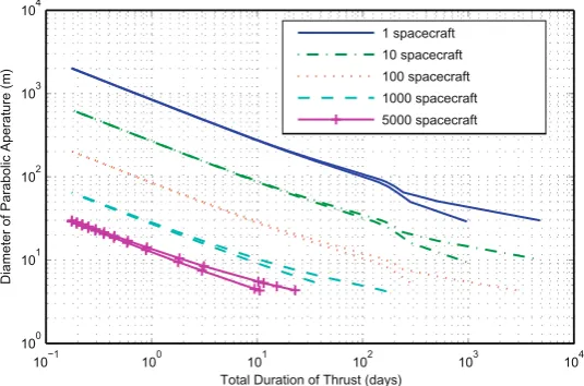
In a recent study[5], it was demonstrated how a significant deviation of the asteroid Apophis could be achieved with a relatively small number of satellites (20–40) each carrying a relatively small primary mirror (between 10 and 40 m in diam-eter).Fig. 1shows a comparison of the required minimum diameter of the aperture of the primary parabolic mirror versus the duration of the thrust. The comparisons were done for different swarm sizes ranging from a single spacecraft (for a base-line comparison) up to 5000. For each swarm size, the diameter of the illuminated spot size on the surface of the asteroid was set to 0.5 m or 1.5 m. The difference can be seen as the duration of the thrust increases; the lower branch corresponds to the 0.5 m spot size, and the upper branch, the 1.5 m. This is expected as the higher the power density, the smaller the spot size (or a higher concentration ratio for the same incoming solar power). The deviation distance was nominally fixed equal to the earth–moon distance at the minimum orbital interception distance (MOID) from the Earth.
However, placing the mirrors in proximity of the asteroid was still an open issue. In particular the analysis of the orbital maintenance of the mirrors was still missing. In this paper, the multi-mirror option is presented together with an analysis of the positioning of the mirrors in the vicinity of the asteroid. A model for two different configurations – a novel single and dual-mirror configuration – will be presented. Apophis is used as case study because of the relatively high threat posed by this particular asteroid.
The first section of the paper will describe the two mirror configurations and the derivation of the force due to the solar pressure acting on the spacecraft. The second section will present a family of formation orbits that can be used to place and control the mirrors. The third section will present an alternative method to place and control the mirrors at artificial equi-librium points (AEPs) in proximity of the asteroid.
2. Mirror design
The design of the device that is focusing the light of the Sun on the surface of the asteroid is a critical aspect of this deflec-tion method. The device has to be able to concentrate a minimum power density at all times (see Sanchez et al.[11]for fur-ther details). Therefore, it is required to have the capability to steer the beam of light to hit any part of the asteroid and to control the concentration factor (or amount of light that is focused on a particular spot).
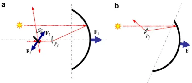
Here we propose two different configurations for the focusing device: a parabolic symmetric primary mirror with colli-mating lens and secondary directional mirror (Fig. 2a), and an asymmetric focusing mirror with collicolli-mating lens and no directional mirror (Fig. 2b). In the former case the primary mirror always points toward the Sun. The lens(es) produces a collimated beam of light that reflects on the secondary mirror and is projected onto the surface of the asteroid. In the latter case the primary mirror should be properly oriented based on the Sun vector. The configuration inFig. 2b can be easily mod-ified by removing the lens and focusing the light directly on the surface of the asteroid. If the light is focused directly on the surface of the asteroid, the focal point has to be moved away from the mirror and the mirror will result in being almost flat.
10−1 100 101 102 103 104
100 101 102 103
Total Duration of Thrust (days)
Diameter of Parabolic Aperature (m)
[image:2.544.141.409.56.233.2]100 spacecraft 1000 spacecraft 5000 spacecraft
Since the mirrors are moving with respect to the asteroid, we introduce a local rotating reference frame centered in the barycenter of the asteroid (Hill’s reference frame inFig. 3). In this reference frame, thex-axis is aligned with the Sun-asteroid vector, they-axis is the direction of motion and thez-axis is perpendicular to the asteroid orbital plane in the direction of the orbital angular momentum.
2.1. Single mirror configuration
The single mirror configuration is composed of an asymmetric adaptive primary mirror and of a collimating lens (or set of lenses). The shape of the primary mirror is assumed to be adaptable such that the focal point can be moved in order to steer the beam in the desired direction.
In order to define the shape of the mirror and its attitude with respect to the Sun we introduce the mirror reference frame inFig. 4, with coordinated axesxM;yM;zM. The mirror reference frame is tilted by an anglebwith respect to the Hill’s
refer-ence frame and is centered in the center of mass of the mirror assembly. Note that in the following analysis we assume that the spacecraft is a point mass and therefore the position of its barycenter does not change for any variation of the shape of the mirror.
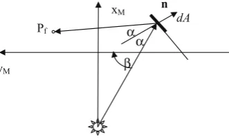
Now, given the position of the focal pointPfin the mirror reference frame and the position of a mirror element with
infin-itesimal area dA, the law of reflection (assuming a perfect reflection) gives us (seeFig. 5): dxM
dyM
¼tan½b
p
=2a
ðxM;yM;xf;yf;bÞ ð1Þwhere½xf;yfis the position of the focal pointPf,bis the Sun aspect angle with respect to the reference frame of the mirror
assembly and
a
is the reflection angle. Note that the anglebalso represents the attitude angle of the mirror reference frame with respect to the Hill’s reference frame and therefore will be referred to as the attitude angle of the mirror in the following. By integrating Eq.(1)with initial conditionsyM0andxM0, we can get the shape of each section of the mirror in thexM–yM [image:3.544.117.424.50.182.2]plane given the position ofPf and the direction of the incoming Sun rays. In the following, we will define the focal distance
Fig. 2.Dual-mirror (left) and single mirror (right) configurations.
[image:3.544.150.386.232.391.2]asfp¼xfxM0. The mirror is then considered to be symmetric with respect to thexM–yMplane such that each section of the
mirror parallel to thexM–zMplane is a parabola with focusPf.
Once the shape and orientation of the mirror are defined, the total force acting on the mirror assembly can be computed by integrating the following expression over the surface of the mirrorA:
dF¼2gMPcos
2
an
dA ð2ÞFSM¼2gMP
Z
A
cos2
an
dA ð3Þwhere the solar pressure at 1AU is P0¼4:563 106N=m2, P is the solar pressure at a distance rd from the Sun
P¼P0ðr1AU=rdÞ2,r1AUis one astronomical unit and
g
Mis the efficiency of the mirror (assumed to be 1.0).2.2. Dual-mirror configuration
For the dual-mirror configuration, three forces have to be taken into account:F1¼
g
priApriPðrd=rdÞis the force due to thesolar pressure acting onto the primary mirror,F2is the force due to the solar pressure acting onto the secondary mirror and F3is the force due to the reflected light from the primary mirror onto the secondary mirror.
The primary mirror in this configuration is assumed to be parabolic and always pointing toward the Sun, while the sec-ondary mirror is flat. Due to the concentration factor, the power density of the reflected light is higher than the one of the direct light, therefore, though the surface of the secondary mirror is smaller than the one of the primary, the reflected solar light exerts a force on the secondary mirror which is
F3¼ ð2gseccos2
a
2Þg
priApriPn2 ð4ÞwhileF2is simply:
F2¼ ð2gseccos2
a
2ÞAsecPn2 ð5ÞBoth forces are acting in the direction normal to the secondary mirror surfacen2.
The total force acting on the mirror assembly (i.e. primary, secondary mirror and lenses) is given by:
FDM¼F1þF2þF3 ð6Þ
expressed as a vector in the local Hill’s reference frame.
[image:4.544.189.359.55.194.2]Δβ
Fig. 4.Definition of the mirror reference frame with respect to the Hill’s rotating reference frame.
β
α
α
[image:4.544.191.357.233.334.2]3. Funnel formation orbits
One option is to consider the asteroid as a point mass and the spacecraft flying in formation with it, the asteroid being the chief or target and the spacecraft the chasers. As a first approximation, the gravity field of the asteroid is considered to have negligible influence on the motion of the spacecraft. This situation corresponds to the spacecraft flying outside the sphere of influence of the asteroid or compensating for its gravity attraction with an active control. Furthermore, it is assumed that no other forces are acting on the spacecraft apart from the gravity attraction of the Sun. The position vector of the spacecraft is therefore given by[12]:
xðhÞ ¼rc
adaacoshdeþ aesinh
g
dMyðhÞ ¼rcsinh
g
3 ð2þecoshÞdeþrccosi rcg
3ð1þecoshÞ 2d
X
þrcdx
þ rcg
3ð1þecoshÞ 2dM
zðhÞ ¼rcsinhdirccoshsinid
X
ð7Þ
wherep¼ ½a;e;i;
x
;X;MTare the orbital parameters of the asteroid,dp¼ ½da;de;di;dx
;dX;dMTtheir variation,g
¼pffiffiffiffiffiffiffiffiffiffiffiffiffiffi1e2, rcis the modulus of the inertial orbital radius of the asteroid,his the true anomaly,h¼hþx
is the true latitude,h¼g
ffiffiffiffiffiffiffiffial
Sp
is the orbital momentum,
l
Sis the gravity constant of the Sun andx,yandzare the local cartesian Hill’s frame coordinates.The motion described by Eq.(7)is governed by the dynamic equations[12]: €
x¼2h_ y_yr_c rc
þxh_2 þ
l
Sr2 c
l
S r3 dðrcþxÞ
€
y¼ 2h_ x_xr_c rc
þyh_2
l
S r3 d y€ z¼
l
Sr3 d z
ð8Þ
We want to maintain a periodic motion of the mirrors in the proximity of the asteroid therefore we impose the condition for periodicityda¼0 which guarantees thatdMis constant.
Given that all the mirrors will have to focus the light onto the same spot, the pointing requirements should be minimized, which implies a close proximity to the asteroid. On the other hand, it is desirable to limit the gravitational perturbations from the asteroid and therefore the satellites should fly outside a limit sphere. In addition, the satellites should avoid impingement with the exhaust gases caused by the sublimation of the asteroid material.
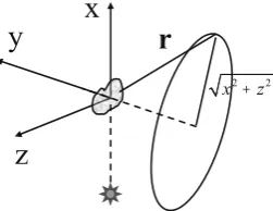
If we assume that the optimal thrust direction that maximizes the deviation is along the unperturbed velocity vector of the asteroid[14,1]then the exhaust gasses will flow along they-axis of the local Hill’s reference frame. The problem can be formulated in mathematical terms as follows (seeFig. 6):
min
dp2Dminh f1¼r ð9Þ
min
dp2Dminh f2¼
ffiffiffiffiffiffiffiffiffiffiffiffiffiffiffi
x2þz2
p
ð10Þ
subject to the constraint: C¼min
h ðrðhÞ rsphÞ>0 ð11Þ
where andrsphis a limit sphere andDis the search space for the solution vectordpandr¼ krkis the modulus of the position
[image:5.544.206.332.576.673.2]vector of the mirror with respect to the asteroidr¼ ½x;y;zT. The problem in Eqs.(9)–(11)was solved with a hybrid stochas-tic-deterministic approach based on a multiagent search technique combined with a decomposition of the search space [6,13].Fig. 7shows the resulting Pareto optimal solutions to Eqs.(9)–(11)forrsph¼2:3 km, which is a limit imposed to avoid the effects of the inhomogeneous gravity field of the asteroid.
+
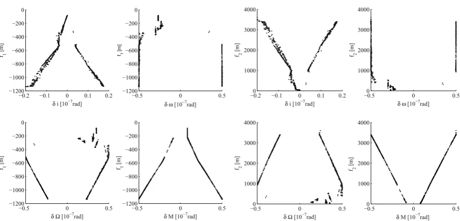
Fig. 8is showing the set of Pareto optimal solutions in the parameter space. As can be seen, the solutions are sym-metrically distributed about the value 0 of thedparameters. It is interesting to note that for the same value ofd
x
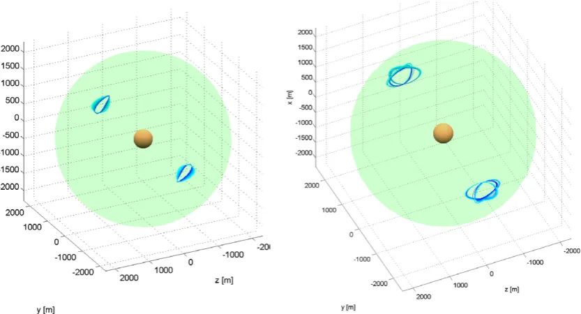
ordX, there are multiple values forf1andf2. This suggests the existence of multiple families of formation orbits with different characteristics with respect to the criteriaf1andf2. The whole set of Pareto optimal orbits are represented inFig. 9. They form twofunnelsgrowing in diameter as the orbits move away from the asteroid. The Pareto front inFig. 7 presents an almost vertical set of points and a ‘knee’ where the front changes slope. The orbits belonging to the vertical set are rep-resented inFig. 10(left graph). In the same figure (right graph), we also plotted some particular solutions with a higher value off1andf2. These solutions form four families of symmetric orbits. The existence of these solutions suggests that the problem may present four complete funnels, and not just two as inFig. 9, where for the other two funnels only few orbits are represented. [image:6.544.153.392.55.239.2]A similar configuration can be also obtained for a limit sphere of 45 km which corresponds to the distance at which the gravity of the asteroid becomes irrelevant. In this case, though, the pointing accuracy would be one order of magnitude higher.
Fig. 7.Pareto front for the funnel orbits problem.
δ δ ω
δ Ω δ
δ δ ω
[image:6.544.48.501.286.504.2]δ Ω δ
3.1. Orbit maintenance
Funnel formation orbits were designed assuming no solar pressure and no gravity attraction from the asteroid. In order to consider the gravity attraction from the asteroid negligible, as mentioned before, the mirror should be placed outside the sphere of influence of the NEO, with a consequent stringent requirement on the pointing capabilities of the mirror. Further-more, although at that distance the gravity of the asteroid becomes negligible, the solar pressure still plays an important role in the dynamics of the spacecraft. Another option is to compensate for the gravity attraction and for the solar pressure. If this strategy is adopted a thrust has to be generated in the opposite direction of the resultant of the two forces.
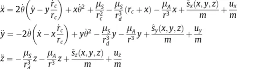
[image:7.544.147.392.55.264.2]Eq.(8)assume that the asteroid is not a gravitational body and that there is no other force than the gravity attraction of the Sun. If the contribution of the gravity field of the asteroid and of the solar pressure are taken into account, Eq.(8)have to be rewritten in the following form:
Fig. 10.Funnel configuration for the solutions of Eq.(9)withrsph¼2300 m: left figure represents the solutions in the vertical part of the Pareto set before
[image:7.544.66.483.301.526.2]the knee, right figure represents two families of symmetric orbits for each funnel.
€
x¼2h_ y_yr_c rc
þxh_2þ
l
S r2 cl
S r3 dðrcþxÞ
l
A r3xþ^ sxðx;y;zÞ
m þ
ux m
€
y¼ 2h_ x_xr_c rc
þyh_2
l
S r3 dy
l
A r3yþ^ syðx;y;zÞ
m þ
uy m
€z¼
l
S r3 dz
l
A r3zþ^szðx;y;zÞ
m þ
uz m
ð12Þ
where
l
Ais the gravity constant of the asteroid,u¼ ½ux;uy;uzTis the control force, m is the mass of the spacecraft, and thecontribution of the solar pressureFSM¼ ½^sx;^sy;^szT is derived from Eq.(6).
[image:8.544.41.507.56.255.2] [image:8.544.66.324.311.380.2]We can now estimate the required control capabilities by plugging the position and velocity time history for the funnel orbits into the equations of motion and solving for the control required to compensate for solar pressure and gravity attrac-tion of the asteroid. We assume here an initial mass of the spacecraftm¼2000 kg and a surface area of the primary mirror Apri¼196 m2with a secondary mirror of 0.5 m in diameter.
Fig. 11represents the three components of the control thrust for the formation orbit at the knee of the Pareto front (left graph) together with the control thrust for the formation orbit furthest away from the asteroid (right graph). It is interesting to note that the magnitude of the control for the two orbits is quite similar. This suggests, as expected, that the controls are mainly compensating for the solar pressure, with the gravity attraction of the asteroid being less significant.
4. Artificial equilibrium points for a solar concentrator
If solar pressure and the gravity field of the asteroid are taken into account then the mirrors can be designed so that the two forces are in equilibrium, with the spacecraft hovering at a fixed location (and distance) from the asteroid. Note that unlike the problem of finding AEPs for a flat reflector[7], here we analyze the case of a curved reflector with pointing constraints.
Considering that the mirror has to constantly reflect the light onto the surface of the asteroid (pointing constraint), if the mirror was flat the only possible equilibrium configuration would be with the asteroid-mirror direction aligned with the spacecraft-Sun direction. If the mirror is not flat, instead, then we can look for possible position vectorsr, solar aspect angles
band focal distancesfpsuch that the vectorFSM¼ ½sx;sy;szTis aligned with the asteroid-mirror direction and:
2h_yr_c rcþ
xh_2 þ
l
Sr2 c
l
Sr3 d
ðrcþxÞ
l
A r3xþsxðx;y;z;b;fpÞ
m ¼0
2h_xr_c rc
þyh_2
l
S r3 dy
l
A r3yþsyðx;y;z;b;fpÞ
m ¼0
l
S r3 dz
l
A r3zþszðx;y;z;b;fpÞ
m ¼0
ð13Þ
θ θ
Note that, the force due to solar pressure is obtained from Eq.(2). In the following, we will consider only the planar case with z¼0, since in this case the third equation in Eq.(13)is satisfied.
Fig. 13represent the misalignment of the force vector due to the solar pressure with respect to the spacecraft-asteroid direction for two different focal lengths. In the figuresLis the length of the projection of the mirror onto theyM axis of
the mirror reference frame. The angleb, as before, is the direction of the light impacting on the mirror whileDbis the angle between the incoming sunlight and the direction of the focal point of the mirror (seeFig. 4). The direction of the focal point identifies the pointing direction. We consider only one quadrant of the Hill’s frame with positivexand negativey. For po-sitivexand positiveythe solutions are symmetric; there are no solutions in the other two quadrants.
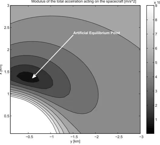
[image:9.544.46.501.479.664.2]As it can be seen forb¼
p
=2, the only equilibrium solutions are along the Sun-asteroid direction. However, in this case the mirror would be in shadow and therefore no equilibrium points can exist along that direction. For higher values ofb, equilibrium points can exist at higher angular distances from the radial direction. For example, forb¼139 deg the mirror can be placed atr¼ ½1:3699;0:48225;0Tkm, which is about 20 deg from the radial direction (Fig. 12shows the level of accel-eration acting on the spacecraft).Fig. 12.Example of AEP at 20 deg from the radial direction.
Δ β [deg]
β
[deg]
0 10 20 30 40 50 60
90 100 110 120 130 140 150 160
-1 -0.8 -0.6 -0.4 -0.2 0 0.2 0.4 0.6 0.8 1
Δ β [deg]
β
[deg]
0 10 20 30 40 50 60
90 100 110 120 130 140 150 160
-1 -0.8 -0.6 -0.4 -0.2 0 0.2 0.4 0.6 0.8 1
Focal Distance=2L Focal Distance=5L/2
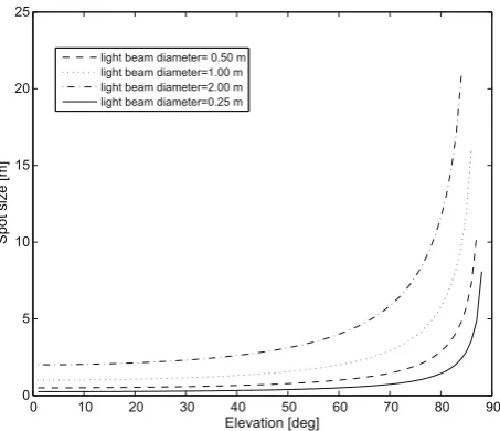
This artificial equilibrium point offers a good location for projecting the light of the Sun on the side of the asteroid along they-direction, and away from the plume of gases. If we assume that the lens produces a collimated light beam with neg-ligible divergence, and that the beam is projected at the intersection of the surface of the asteroid with they-axis, then we can compute where the two extreme points of the beam intersect the surface of the asteroid. From this intersection, we can compute the spot size given the beam size and the elevation over they-axis. As can be seen inFig. 15, for a beam size be-tween 0.5 and 1 m in diameter, the increase in spot size due to an elevation of 70°along they-axis and 20°from the radial x-axis, is still limited.Fig. 14shows a set of artificial equilibrium points for different surface areas of the mirror and for ele-vation angles from 60 to 90 degrees.
4.1. Orbit maintenance
Solar pressure depends on the distance from the Sun, therefore, if the size of the mirror is constant, as the asteroid moves around the Sun the force acting to the spacecraft changes with the true anomalyh. As a consequence, the position of the equilibrium points changes with time unless the orbit of the asteroid is circular.
0 −100 −200 −300 −400 −500 −600 −700 −800 −900
800 900 1000 1100 1200 1300 1400 1500 1600
y [km]
x [km]
A=196 m2 A=144 m2
[image:10.544.152.394.56.271.2]A=100 m2 A=64 m2
Fig. 14.Artificial equilibrium points for different mirror sizes.
0 10 20 30 40 50 60 70 80 90
0 5 10 15 20 25
Elevation [deg]
Spot size [m]
light beam diameter= 0.50 m light beam diameter=1.00 m light beam diameter=2.00 m light beam diameter=0.25 m
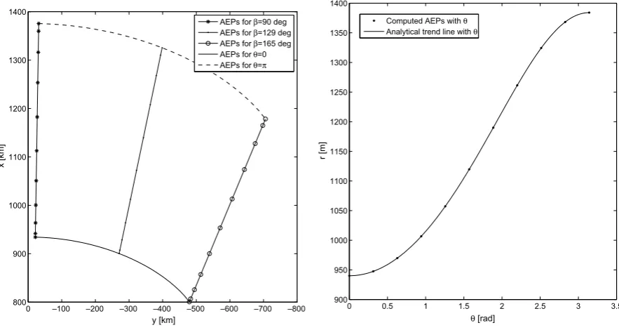
[image:10.544.160.387.307.502.2]Fig. 16shows, for different attitudes of the mirror (left plot), the position of the equilibrium points over a full orbit of the asteroid Apophis.Fig. 16also shows (right plot) the variation of the position of the AEP for a particular attitude of the mirror, over half an orbit. The black dots represent the computed position of the equilibrium points for an angleb¼129 deg while the continuous line is given by the following equations,
xAEP¼rAEPðh0Þcosð
Þð1þecosðh0ÞÞ=ð1þecosðhÞÞ yAEP¼rAEPðh0ÞsinðÞð1þecosðh0ÞÞ=ð1þecosðhÞÞð14Þ
where
¼arctan yAEPðh0ÞxAEPðh0Þ h i
is the angular position of the AEP forh¼h0. Then, the distance of the AEP from the asteroid varies with the following law:
rAEP¼rAEPðh0Þð1þecosðh0ÞÞ=ð1þecosðhÞÞ ð15Þ
Since the AEPs are moving, a spacecraft placed at an AEP would move toward the asteroid or away from the asteroid depend-ing on the initialh. Specifically, forh2 ½0;
p
the spacecraft would fall toward the asteroid, while forh2 ½p
;2p
the spacecraft would escape along the radial direction.We can envisage two strategies to maintain the orbital position of the mirror: compensating for solar pressure and gravity attraction with an active control (low-thrust)or letting the spacecraft drift along the radial direction chasing the position of the equilibrium points.
In order to chase the AEP the spacecraft has to move with the same kinematics, therefore we can impose the following velocity and acceleration:
dx dt¼
drAEP
dt cosð
Þ dy dt¼drAEP
dt sinð
Þ ð16Þd2x dt2¼
d2rAEP
dt2 cosð
Þd2y dt2¼
d2rAEP
dt2 sinð
Þ ð17Þwith drAEP
dt ¼ r2
AEPesinðhÞh_ rAEP0
ð18Þ
d2rAEP
dt2 ¼ erAEP rAEP0
2r_AEPsinðhÞh_þrAEPcosðhÞh_2þrAEPsinðhÞ€h
h i
ð19Þ
Eqs.(16) and (17)represent an imposed shape to the motion of the spacecraft. If we then substitute Eqs.(14), (16) and (17) into the dynamic equations and solve for the controls we can get the required thrust components to follow the prescribed kinematics.
0 —100 —200 —300 —400 —500 —600 —700 —800
800 900 1000 1100 1200 1300 1400 y [km] x [km]
AEPs for β=90 deg
AEPs for β=129 deg
AEPs for β=165 deg
AEPs for θ=0
AEPs for θ=π
0 0.5 1 1.5 2 2.5 3 3.5
900 950 1000 1050 1100 1150 1200 1250 1300 1350 1400
θ [rad]
r [m]
Computed AEPs with θ
Analytical trend line with θ
AEP. A possible scenario, therefore, is that the swarm can be distributed around the asteroid at different angles
and the mirrors would move back and forth along the radial directions.4.2. AEPs for a non-spherical asteroid
The analysis presented in the previous section is valid for a spherical asteroid with a homogenous gravity field. However asteroids have an irregular shape with a very inhomogeneous gravity field. As done previously by other authors, we can as-sume that the asteroid is an ellipsoid with semi-axesaI,bIandcI(seeFig. 18). In particular we assume that the semi-axiscIis
aligned with thez-axis of the Hill’s frame and that the asteroid is rotating around thez-axis with angular velocity
x
R. Notethat the rotation aroundzis most likely not the only motion associated to an irregular asteroid. For example, it can be ex-pected that an irregular body is also wobbling but these additional motion components are not considered in the present analysis. Furthermore, during the ablation process the mass of the asteroid changes (see Ref.[11]) as well as its shape. In fact, the strategy considered here and in Sanchez et al.[11]is not to track a fixed spot on the surface of the asteroid but to keep the direction of the beam substantivally fixed, as the surface of the asteroid moves under the spotlight. The result is to plough the asteroid as the sub-satellite point is moving along its surface. Moreover, in the ideal case, the lenses should generate a perfectly collimated beam, thus no adaptive focusing would be needed when the surface of the asteroid moves away or closer to the mirror. In the real case, instead, it is expected that the position of the lenses can be controlled to im-prove the focusing of the beam. However, even the change in mass and shape of the asteroid is not considered in the present analysis, as it is minimal over short periods of time, and will be addressed in a future study.
1 2 3 4 5 6 7 8
−10 −8 −6 −4 −2 0 2 4 6 8x 10
−4
Control Components [N]
θ [rad]
β=129 deg
ux uy uz
0 50 100 150 200 250 300 350 400
−4 −3 −2 −1 0 1 2 3 4 5 6x 10
−8
θ [deg]
Control Components [N]
ux
[image:12.544.40.508.303.508.2]uy uz
Fig. 17.Control profiles for orbit maintenance forA¼196 m2.
[image:12.544.189.355.545.675.2]With this assumptions we can express the gravity field of the asteroid as the sum of a spherical field plus a second-degree and second-order field[2,9]:
U20þ22¼
l
Ar3 C20 1
3 2cos
2d
þ3C22cos2dcos 2k
ð20Þ
where the harmonic coefficientsC20andC22can be expressed as a function of the semi-axes: C20¼
1 10 2c
2 I a
2 I b
2 I
C20¼
1 20 a
2 I b
2 I
ð21Þ
and the anglesdandkare defined as
d¼0
k¼arctan y x þ
x
Rtð22Þ —240 —260 —280 —300 —320 —340 —360 —380 —400 —420
850 900 950 1000 1050 1100 1150 1200 1250 1300 1350 y [m] x [m] b I/aI=0.34 b
I/aI=0.51 b
I/aI=0.73
—250 —260 —270 —280 —290 —300
880 900 920 940 960 980 y [m] x [m] b I/aI=0.34 b
I/aI=0.51 b
[image:13.544.44.505.56.235.2]I/aI=0.73
Fig. 19.AEPs for a non-spherical asteroid: (left) AEPs for different elongations and for a full revolutions of the asteroid; (right) a close up for few degrees around the perihelion.
0 50 100 150 200 250 300 350 400
−8 −7 −6 −5 −4 −3 −2 −1
0x 10 −5
θ [deg]
Control Components [N]
ux, bI/aI=0.34
uy,bI/aI=0.34
ux, bI/aI=0.51
uy,bI/aI=0.51
ux,bI/aI=0.73
uy,bI/aI=0.73
[image:13.544.154.386.285.492.2]2h_yrc rcþ
xh_2þ
l
S r2 cl
S r3 dðrcþxÞ
l
A r3xþsx mþ
oU20þ22
ox ¼0
2h_xr_c rc
þyh_2
l
S r3 dy
l
A r3yþsy mþ
oU20þ22
oy ¼0
l
S r3 dz
l
A r3zþsz mþ
oU20þ22
oz ¼0
ð23Þ
We assume an angular speed of one revolution every 30 hours as for the astroid Apophis and three different elongations: bI=aI¼0:73,bI=aI¼0:51 andbI=aI¼0:34. Since we are interested only in the in-plane motion, we can setcI¼bI.Fig. 19
shows the position of the AEPs for the three different elongations over one full orbit of the asteroid around the Sun. If now we apply the same control strategy as proposed in the previous section and we force the spacecraft to follow the position of the AEP for a spherical asteroid we get the control profiles represented inFig. 20.
5. Final remarks
In this paper we presented an analysis of the proximal motion of a set of mirrors with respect to an asteroid. Two con-figurations for the mirrors were analyzed and for each one a different strategy for orbit maintenance was considered. In par-ticular, the dual-mirror configuration led to the definition of a particular set of formation orbits composing two symmetric funnels with the principal axis aligned with they-axis of the Hill’s reference frame. These funnel orbits allow the spacecraft to have a very good visibility of the target spot on the surface of the asteroid and at the same time give some room for the plume of gas to flow with minimal impingement. The funnel orbits are located outside a limit sphere, where the gravity field of the asteroid can be considered homogenous. This limit sphere imposes a requirement on the pointing accuracy and on the focusing capabilities of the mirror assembling. A second option considered a single mirror configuration. For this second op-tion the mirror can be placed at artificial equilibrium points quite inclined over they-axis of the Hill frame. From this posi-tion, the spacecraft sees the target point on the surface of the asteroid from a high elevation angle. However, AEPs can be found such that the distortion of the spot area due to the elevation angle is limited. For this second option a control strategy was proposed that allows the spacecraft to oscillate in a confined region in the proximity of the asteroid with very low con-trol thrust. Even adding the effect of the gravity field of an elongated body the magnitude of the required concon-trol thrust re-mains limited. The low level of thrust would suggest the use of FEEP engines, which would lead to a minimal propellant consumption even over long operation times.
Acknowledgement
This research is partially supported by the ESA/Ariadna Study Grant AO/1-5387/07/NL/CB. The author would like to thank the reviewers for contributing to the improvement of this article.
References
[1] Colombo C, Vasile M, Optimal trajectories for NEO deflection. In: Proceedings of the 58th International Astronautical Congress, IAC-07-C1.4.02. Hyderabad, India; 2007.
[2] Hu W, Scheeres DJ. Spacecraft motion about slowly rotating asteroids. J Guidance Control Dyn 2002;25(4):765–75.
[3] Kahle R, Kuhrt E, Hahn G, Knollenberg J. Physical limits of solar collectors in deflecting earth-threatening asteroids. Aerospace Sci Technol 2006;10:256–63.
[4] Lunan D. Need we protect earth from space objects and if so, how? Space Policy 1992;8(1):90–1.
[5] Maddock C, Sanchez Cuartielles JP, Vasile M, Radice G. Comparison of single and multi-spacecraft configurations for NEA deflection by solar sublimation. In: AIP Conference Proceedings 886: New Trends in Astrodynamics and Applications III, Princeton, USA; 2007. p. 303–16.
[6] Maddock C, Vasile M. Design of optimal spacecraft-asteroid formation through a hybrid global optimization approach. Int J Intell Comput Cybernet 2008;1(2):239–68.
[7] McInnes C. Non-Keplerian orbits for mars solar reflectors. J Br Interplanet Soc 2002;75:74–84. [8] Melosh HJ, Nemchinov IV. Solar asteroid diversion. Nature 1993;366(366):21–2.
[9] Rossi A, Marzari F, Farinella P. Orbital evolution around irregular bodies. Earth Planets Space 1999;51:1173–80.
[10] Sanchez Cuartielles JP, Colombo C, Vasile M, Radice G. A multi-criteria assessment of deflection methods for dangerous NEOs. In: AIP conference proceedings 886: New Trends in Astrodynamics and Applications III. Princeton, USA, 2007. p. 317–33.
[11] Sanchez Cuartielles JP, Colombo C, Vasile M, Radice G. Multi-criteria comparison among several mitigation strategies for dangerous near earth objects. J Guidance Control Dyn; in press.
[12] Schaub H, Junkins JL. Analytical mechanics of space systems. AIAA Education Series, Virginia, USA; 2003.