Int. J. Electrochem. Sci., 13 (2018) 9592 – 9599, doi: 10.20964/2018.10.21
International Journal of
ELECTROCHEMICAL
SCIENCE
www.electrochemsci.org
Short Communication
Sn/C Composite as Anode Material for Lithium-Ion Batteries
with Humic Acid as Carbon Source
Shuzhen Yang1, Yanfang Huang1, Guihong Han1,*, Jiongtian Liu1, Yijun Cao2
1
School of Chemical Engineering and Energy, Zhengzhou University, Zhengzhou 450001, P. R. China.
2
Henan Province Industrial Technology Research Institure of Resources and Materials, Zhengzhou University, Zhengzhou 450001, P. R. China.
*
E-mail: [email protected]
Received: 8 June 2018 / Accepted: 13 July 2018 / Published: 1 September 2018
Sn/C anode materials were synthesized from SnO2 particles with humics as carbon source for coating
with a simple solid-phase-reduction strategy. XRD and SEM show that the materials consist of Sn and C, with Sn completely encapsulated by carbon. The carbon film can accommodate the volume expansion of Sn particles and considerably improve the electrical conductivity of the anode. The Sn/C anode materials have initial specific capacities of 1215 and 556 mAh·g−1 in the first discharge and charge (100 mA·g−1), respectively. The discharge capacity is 387 mAh·g−1 after 50 cycles (coulombic efficiency = 98.2%). Electrochemical impedance spectroscopy (EIS) indicates that the Sn/C prepared from humics as carbon source has markedly improved charge-transfer kinetics compared with Sn/C-s anode (having sucrose as carbon source). Humics can be considered as a highly advantageous carbon source for coatings to enhance the electrochemical performance of Sn-based anode for lithium-ion batteries.
Keywords: Sn/C; Humics; Carbon coating; Anode; Lithium-ion battery
1. INTRODUCTION
Lithium-ion batteries (LIBs) have become the leading power-storage tool since its introduction into commercial applications [1, 2]. The most common graphite anode offers a theoretical capacity of 372 mA g−1, which is markedly lower than those of alloy-type anodes (Sn, Si, and Al) [3, 4, 5]. As one of the most promising anode materials, tin possesses a theoretical capacity of 992 mAh·g−1 (Li4.4Sn)
an abundant reserve of humics. Humics are highly oxidized and contain numerous oxygenated groups around the edges of the graphene-like core [17], exhibiting its potential as an electric material. The application of humics in materials for lithium-ion battery is of certain research value. However, the use of humics as carbon source to encapsulate and modify anode materials has been rarely reported to date. Here, we consider humics as a novel and green carbon source to coat Sn anodes. First, we prepared SnO2 particles by simple hydrothermal method, then we used liquid-phase self-assembly method to
coat humics on the particle surface. Finally, Sn/C composites were obtained by solid-state reduction. During calcination, humics was carbonized and SnO2 was simultaneously reduced by carbon to Sn.
2. EXPERIMENTAL
Humics (humid acid) as carbon source was purchased from Tianjin Zhiyuan Reagent Co., Ltd., China. Original humic acid was further purified by repeat precipitation and redissolution with 0.1 M HCl and 0.1 M NaOH, respectively, before coating [18]. Typically, 10 g of humics was added into 100 mL of 0.1 M NaOH solution. The solution was stirred for 30 min at 60 °C in the water bath. Then, the supernatant was centrifuged and acidified with 1 M hydrochloric acid to a pH of 1.0. The precipitate was collected, and the process was repeated for three times. Purified humic acid was obtained by centrifugal washing of the final precipitate with distilled water for several times. To obtain suitable carbonization temperature, we studied the decomposition of humics through thermogravimetry– differential scanning calorimetry (TG–DSC) technology. The thermal and mass changes of humics with temperature increase can be found from Fig. 1. The carbonization of aromatic carbon mainly occurs when the temperature exceeds 641.1 °C. SnO2 spheres were synthesized as reported [7].
[image:2.596.178.420.568.737.2]
Figure 2. Diagram of Sn/C synthesis.
Sn/C composites was synthesized as follows: typically, 0.4 g of purified humics was dissolved in appropriate amount of 0.5 mol·L−1 NaOH solution with stirring and heating mildly. Then, 0.3 g of SnO2 was added to the solution. The solution was heated to evaporate water under stirring. Afterward,
the solid was ground to fine power with agate mortar. Finally, the powder was calcined at 1000 °C for 2 h to be carbonized under N2 atmosphere. The powder was washed by deionized water for several
times to eliminate soluble salts. The product was obtained by drying in vacuum oven at 60 °C for 12 h. The concise experimental process is shown in Fig. 2. For comparison, Sn/C-s (with sucrose as carbon source) was prepared under the same condition.
The crystal structures of SnO2 and Sn/C were characterized by X-ray diffraction (XRD), which
were carried out by D8 Adance diffractometer with Cu Kα radiation (λ=1.5406 Å) at a scanning rate of 0.2·s−1. The morphology of Sn/C was observed by scanning electron microscopy (SEM), conducting by TSM-7500F field-emission scanning electron microscopy. Sn/C was sputtered with platinum before being transferred into vacuum chamber. The mass ratio of elements Sn and C was obtained by energy dispersive X-ray spectroscopy (EDS). The distribution of Sn and C was distinguished by transmission electron microscopy (TEM) images, which were obtained from FEI TalosF 200S. TG–DSC experiments were performed on a Netzsch 449 C thermal analyzer at a heating rate of 5 °C min−1 from 20 °C to 1200 °C in N2.
The electrochemical performance of the Sn/C sample was evaluated galvanostatically on CR2032 coin. The metallic lithium foil was used as counter electrode. Anodes were composed of prepared samples, acetylene black, and poly (vinylidene fluoride) at the ratio of 8:1:1 in weight. The electrolyte consisted of 1 M LiPF6 dissolved in 1:1:1 ethylene carbonate/ethyl methyl
carbonate/dimethyl carbonate. Porous polypropylene (Celgard 2500) was used as separator. Cells were assembled in an Ar-filled glove box, where contents of H2O and O2 were both lower than 0.1 ppm.
3. RESULTS AND DISCUSSION
The XRD patterns (Fig. 3a) show that all peaks are consistent with SnO2. All diffraction peaks
in Fig. 3b can be readily indexed to the pure phase of Sn with a tetragonal structure. No SnO or SnO2
[image:3.596.107.466.72.178.2]Figure 3. XRD patterns of (a) precursor SnO2 and (b) Sn/C.
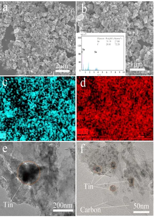
Figure 4. (a), (b) SEM of Sn/C particles in different magnification (insert: EDS pattern of the as-synthesized Sn/C), (c, d) element mappings of Sn and C, and (e, f) TEM images of Sn/C particles.
[image:4.596.114.483.72.213.2] [image:4.596.176.424.267.615.2]
encapsulated with amorphous carbon completely, and the diameter of Sn core is about 200 nm. The morphology of carbon particles presents no definite shape and appears in laminated slices, which can provide additional reserved space for the volume expansion of SnO2. Several fine particles of Sn are
embedded in the carbon body. The coated carbon layer prohibits the volume expansion of tin [19]. Auxiliary experiments have proved that the carbon content in this study is appropriate.
Electrochemical performance of Sn/C composites is shown in Fig. 5. The cyclic voltammetry (CV) curves of Sn/C composites (Fig. 5a) show several irreversible reduction peaks in the first discharge, which are mainly derived from the decomposition of electrolyte and the formation of solid electrode interface on the surface of Sn/C particles [9]. The irreversible peaks are almost not observed in the following two cycles [9, 17]. The curves are almost in the same shape for the second and third cycles, meaning that excellent electrode charge and discharge processes. Xu et al. [9] obtained similar results. For initial cycling, the Sn/C electrode exhibits a discharge and charge capacities of 1215 and 556 mAh·g−1 respectively, with a coulombic efficiency of 45.5% (Fig. 5b). Reversible capacity remains at 387 mAh g−1 after 50 cycles.
Figure 5. (a) CV curves of Sn/C, scan rate: 0.3 mV·s−1, (b) cycle performance of Sn/C with Sn/C-s and precursor SnO2, current density of 100 mA·g−1, (c) rate performance of Sn/C, all voltage range:
0.005–3.0 V versus Li/Li+; Nyquist plots of the electrodes Sn/C and Sn/C-s, and (d) at 0.4 V during the charge of 4th cycle, AC amplitude: 5 mV, frequency range: 10−2–105 Hz, insert: equivalent circuit mode plot.
The comparison of cycle performance of Sn/C with Sn/C-s (C from sucrose) and precursor SnO2 is shown in Fig. 5b. Sn/C shows better performance than SnO2 and Sn/C-s. For SnO2, irreversible
reaction of SnO2 to Sn and volume expansion occur [4,11]. The specific capacity of Sn/C is higher
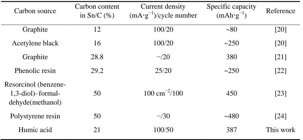
[image:5.596.104.487.325.599.2]experimental condition, Sn/C obtained from the carbon source of the phenolic resin exhibited a specific capacity of ~250 mAhg−1 at a current density of 25 mAg−1
[22]. The structure of Sn nanoparticles uniformly embedded in carbon obtained from the organometallic tin precursor with other organic carbon sources can exhibit a stable cycle performance [23, 24]. However, the price for producing these materials may be too high for applications.
Table 1. The comparison of carbon source with literatures.
The rate performance of Sn/C are displayed in Fig. 5c. The Sn/C electrode capacity continued to decreasing, and coulombic efficiency remained increasing during the first 10 cycles at 0.1 C. Thereafter, the specific capacity tended to be stable at different rate levels. The specific capacity returns to 400 mAh·g−1 when current density is at a rate of 0.1 C. After 3 cycling times, EIS (Fig. 5d) was tested at 0.4 V when the battery was charged to 0.4 V of 4th cycle to obtain an identical status. The high-frequency semicircle reflects the resistances of surface film (Rp1), and medium-frequency
semicircle reflects charge-transfer (Rp2) [25]. The equivalent circuit mode plot can be found in Fig. 5d.
The curves were fitted by ZView software, and the parameters obtained from fitting are listed in Table 2. As seen in Table 1, Sn/C exhibits lower surface film resistance (23.56 Ω vs. 33.22 Ω) and charge-transfer resistance (47.78 Ω vs. 49.77 Ω) than Sn/C-s, and its Warburg resistance is considerably lower than that of Sn/C-s (58.5 Ω vs. 290.4 Ω). The Sn/C materials using humic acid as carbon source exhibit markedly improved charge-transfer kinetics.
Carbon source Carbon content in Sn/C (%)
Current density (mAg−1
)/cycle number
Specific capacity (mAhg−1
) Reference
Graphite 12 100/20 ~80 [20]
Acetylene black 16 100/20 ~250 [20]
Graphite 28.8 −/20 380 [21]
Phenolic resin 29.2 25/20 ~250 [22]
Resorcinol (benzene- 1,3-diol)–formal-dehyde(methanol)
50 100 cm−2/100 450 [23]
Polystyrene resin 50 −/30 ~480 [24]
[image:6.596.43.546.277.510.2]
Table 2. Parameters obtained from fitting of impedance spectra by the equivalent circuit mode.
Samples Rs () Rp1 () (μMho) CPE1-T Rp2 () CPE(μMho) 2-T W-R ()
Sn/C 4.21 23.56 13.78 47.78 170.12 58.5
Sn/C-s 6.69 33.22 17.29 49.77 76.69 290.4
4. CONCLUSIONS
We obtained a Sn/C anode material through a simple solid-phase reduction strategy with humics as carbon precursor. Sn was coated by carbon successfully, and the distribution of Sn and C was generally uniform. The electrochemical performance of Sn/C anode was considerably enhanced. The cycle performance, rate capability, and charge-transfer kinetics of Sn/C from humics are superior to those of Sn/C-s from sucrose. Reversible capacity is maintained at 387 mAh·g−1 after 50 cycle times. By using humics as carbon precursor, Sn/C composite exhibits considerable potential as an anode material for LIBs.
ACKNOWLEDGMENTS
This work was supported by the National Science Fund of China (No. 51674225 and No. 51774252); the China Postdoctoral Science Foundation (No. 2017M622375); and the Educational Commission Fund of Henan Province of China (No. 17A450001, No. 18HASTIT011 and No. 18A450001).
References
1. J.M. Tarascon, M. Armand, Nature, 414 (2001) 359.
2. G. Derrien, J. Hassoun, S. Panero, B. Scrosati, Adv. Mater., 19 (2007) 2336.
3. S. Li, J. Niu, Y.C. Zhao, K.P. So, C. Wang, C.A. Wang, J. Li, Nat. Commun., 6 (2015) 7872. 4. A. Sivashanmugam, T.P. Kumar, N.G. Renganathan, S. Gopukumar, M. Wohlfahrt-Mehrens, J.
Garche, J. Power Sources, 144 (2005) 197.
5. H. Wu, G. Yu, L. Pan, N. Liu, M.T. McDowell, Z. Bao, Y. Cui, Nat. Commun., 4 (2013) 1943. 6. A.H. Whitehead, J.M. Elliott, J.R. Owen, J. Power Sources, 81 (1999) 33.
7. W.-M. Zhang, J.-S. Hu, Y.-G. Guo, S.-F. Zheng, L.-S. Zhong, W.-G. Song, L.-J. Wan, Adv. Mater., 20 (2008) 1160.
8. C. Cui, X. Liu, N. Wu, Y. Sun, Mater. Lett., 143 (2015) 35.
9. Y. Xu, Q. Liu, Y. Zhu, Y. Liu, A. Langrock, M.R. Zachariah, C. Wang, Nano Lett., 13 (2013) 470. 10.Y. Yu, L. Gu, C. Zhu, P.A. van Aken, J. Maier, J. Amer. Chem. Soc., 131 (2009) 15984.
11.Z.-Q. Wang, M.-S. Wang, Z.-L. Yang, Y.-S. Bai, Y. Ma, G.-L. Wang, Y. Huang, X. Li, ChemElectroChem., 4 (2017) 345.
12.C.-M. Park, W.-S. Chang, H. Jung, J.-H. Kim, H.-J. Sohn, Electrochem. Commun., 11 (2009) 2165. 13.Z. Shen, Y. Hu, Y. Chen, X. Zhang, K. Wang, R. Chen, J. Power Sources, 278 (2015) 660.
21.G.X. Wang, J.H. Ahn, M.J. Lindsay, L. Sun, D.H. Bradhurst, S.X. Dou, H.K. Liu, J. Power Sources, 97 (2001)211.
22.K.Wang, X. He, J. Ren, C. Jiang, C. Wan, Electrochem. Solid-State Lett., 9 (2006) A320. 23.J. Hassoun, G. Derrien, S. Panero, B. Scrosati, Adv. Mater., 20 (2008) 3169.
24.I.S. Kim, G.E. Blomgren, P.N. Kumta, Electrochem. Solid-State Lett., 7 (2004) A44. 25.S. Yang, Y. Huang, G. Han, J. Liu, Y. Cao, Powder Technol., 322(2017)84.