This is a repository copy of
Manipulation Planning Under Changing External Forces
.
White Rose Research Online URL for this paper:
http://eprints.whiterose.ac.uk/133934/
Version: Accepted Version
Proceedings Paper:
Chen, L, Figueredo, LFC orcid.org/0000-0002-0759-3000 and Dogar, M
orcid.org/0000-0002-6896-5461 (2019) Manipulation Planning Under Changing External
Forces. In: Proceedings of the IEEE/RSJ International Conference on Intelligent Robots
and Systems (IROS 2018). IROS 2018: IEEE/RSJ International Conference on Intelligent
Robots and Systems, 01-05 Oct 2018, Madrid, Spain. IEEE , pp. 3503-3510. ISBN
978-1-5386-8094-0
https://doi.org/10.1109/IROS.2018.8593555
© 2018 IEEE. This is an author produced version of a paper published in Proceedings of
the IEEE/RSJ International Conference on Intelligent Robots and Systems (IROS 2018).
Personal use of this material is permitted. Permission from IEEE must be obtained for all
other uses, in any current or future media, including reprinting/republishing this material for
advertising or promotional purposes, creating new collective works, for resale or
redistribution to servers or lists, or reuse of any copyrighted component of this work in
other works. Uploaded in accordance with the publisher's self-archiving policy.
[email protected] https://eprints.whiterose.ac.uk/ Reuse
Items deposited in White Rose Research Online are protected by copyright, with all rights reserved unless indicated otherwise. They may be downloaded and/or printed for private study, or other acts as permitted by national copyright laws. The publisher or other rights holders may allow further reproduction and re-use of the full text version. This is indicated by the licence information on the White Rose Research Online record for the item.
Takedown
If you consider content in White Rose Research Online to be in breach of UK law, please notify us by
Manipulation Planning under Changing External Forces
Lipeng Chen, Luis F. C. Figueredo, Mehmet Dogar
Abstract— We present a manipulation planning algorithm for a robot to keep an object stable under changing external forces. We particularly focus on the case where a human may be applying forceful operations, e.g. cutting or drilling, on an object that the robot is holding. The planner produces an efficient plan by intelligently deciding when the robot should change its grasp on the object as the human applies the forces. The planner also tries to choose subsequent grasps such that they will minimize the number of regrasps that will be required in the long-term. Furthermore, as it switches from one grasp to the other, the planner solves the problem of bimanual regrasp planning, where the object is not placed on a support surface, but instead it is held by a single gripper until the second gripper moves to a new position on the object. This requires the planner to also reason about the stability of the object under gravity. We provide an implementation on a bimanual robot and present experiments to show the performance of our planner.
I. INTRODUCTION
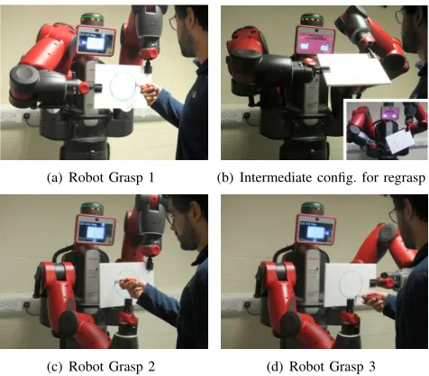
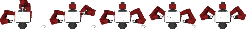
We are interested in the problem of a robot manipulating an object that is under the application of changing external forces. Take the example in Fig. 1, where a human is cutting a circular piece out of a board. During the cutting operation, the human exerts forces on the board that change position, direction, and magnitude. To keep the object stable against these forces, the robot changes its grasp on the object multiple times. In this paper we propose a planner that enables a robot to keep an object stable under changing external forces like this.
There are two key problems our planner solves.
First, our planner produces an efficient plan by minimizing the number of times the robot needs to regrasp the object. For example in Fig. 1, the robot changes its grippers’ position only 2 times (counting each gripper separately) during the whole operation. This requires the planner to decidewhento regrasp during the course of the interaction. It also requires the planner to choose grasps intelligently. A bad grasp may result in failure; for example the object may slip through the fingers during a cutting action (Fig. 2(a)), or it may bend away from the desired pose due to large torques around the gripper during a drilling action (Fig. 2(b)).
Second, our planner plans each regrasp. A regrasp requires the robot to release its grippers off the object and then to grasp the object at different points. However, when the robot releases a gripper, the object may become unstable under external forces. Even if we assume the human in Fig. 1(a)
This project has received funding from the European Union’s Horizon 2020 research and innovation programme under the Marie Sklodowska-Curie grants agreement No. 746143 and 795714, and from the UK Engi-neering and Physical Sciences Research Council under grant EP/P019560/1. Authors are with School of Computing, University of Leeds, Leeds, UK,
{sclc, l.figueredo, m.r.dogar}@leeds.ac.uk
(a) Robot Grasp 1 (b) Intermediate config. for regrasp
[image:2.612.320.558.143.352.2](c) Robot Grasp 2 (d) Robot Grasp 3
Fig. 1. Cutting a circular piece out of a board.
(a) Object slides between fingers (b) Object bends due to large torque
Fig. 2. Failure during cutting (a) and drilling (b).
stops applying forces during regrasps, the object can still become unstable due to gravity. For example, to regrasp the object from the configuration in Fig. 1(a) to the one in Fig. 1(c), if the robot simply releases its right gripper, a heavy object may slip within the remaining gripper as shown in the small figure at the right bottom of Fig. 1(b). Therefore, the robot may need to change the position of the object before releasing one of its grippers. Fig. 1(b) shows such an intermediate pose, where the object is stable even when the right gripper releases it.
[image:2.612.322.559.389.481.2]problem in the case of multiple manipulators for assembly-like tasks [4], [5], [6], [7].
We build on and extend this literature in three novel ways. First, in addition to the kinematic and geometric (e.g. collision) constraints, we also consider stability constraints due to the changing external forces acting on the manipulated object. Multi-step manipulation planners need to go beyond geometric constraints. In our task, for example, the robot is not required to move the object to any goal position but is simply required to keep the object stable. Still, due to the sequence of external forces acting on the object, the robot needs to plan regrasps and the corresponding motions, possibly moving the object as a result. In this paper we present such a manipulation planner. Similar to Bretl [8] we formulate the problem as first identifying the stable intersections between different grasp manifolds and then connecting these intersections.
Second, we solve the problem of regrasp planning “in-the-air” using two manipulators. Existing work in regrasp planning focuses on placing an object on a support surface and then regrasping it with a new gripper pose [5], [6], [7]. In our task, the robot performs the regrasp without placing the object on a surface. Instead, it goes through a sequence of unimanual and bimanual grasps to reach different grasps. This, however, requires our planner to also evaluate the stability of the object against gravity, particularly during unimanual grasps.
Third, we are interested in addressing multi-step manipula-tion planning in ahuman-robot interactionsetting. Therefore we strive to minimize the number of different grasps required to hold the object stable against external forces. We also have constraints in terms of where we position the object in space to make it possible for the human to apply the forces. Existing work in forceful human-robot collaboration mostly focuses on the control problem [9], [10], [11], solving for the necessary stiffness of manipulator joints as an external force is applied, and assumes the object to be already grasped at pre-specified points by the robot. We approach the problem from the manipulation planning point of view and instead address the decision of what grasps to use and when/how to switch between them. Other work in planning for human-robot collaboration exists [12], [13], [14] which focus on handing-over an object to a human, or avoiding colliding a human working in the same workspace. To the best of our knowledge our work is the first one to take a planning approach to the human-robot collaboration problem where the human applies multiple changing forces on an object grasped by the robot.
II. PROBLEM DEFINITION
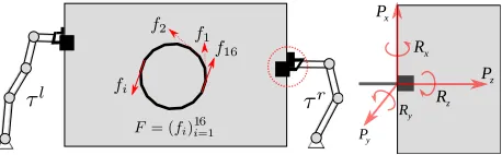
In this paper, we are interested in scenarios where forces are exerted on the object grasped by the robot. We use f to refer to a force vector, defined in the object’s coordinate frame. Then, we represent a forceful task to be executed on the object as a sequence of forcesF = (fi)mi=1. For example,
in Fig. 3-Left, a sequence of sixteen force vectors tangential to the circle represent the circular cutting task in Fig. 3.
y
P
z
P
x
P
x
R
z R
y
R
Fig. 3. Left: The task is represented as a sequence of forcesF= (fi)mi=1.
Right: We estimate the force/torque limits of a grip on the object along the three main axes.
Here, we assume the robot has two manipulators for clarity of explanation and because the robot we use in our experiments has two arms. However, our formulation can easily be extended to more manipulators. We assume each manipulator is equipped with a gripper. Let CSl, CSr be
the configuration space of the left and right manipulator, and SE(3) be the configuration space of the object. The composite configuration spaceCSis their Cartesian product CS=CSl×CSr×SE(3). Each composite configuration q in CS can then be written as q = (ql, qr, x), where ql∈CSl,qr∈CSr, andx∈SE(3).
We also define agrasp,g, using the pose of the gripper(s) on the object. A bimanual grasp specifies poses for both the left and right grippers. A unimanual grasp specifies the pose of only one gripper. Such gripper poses can be generated using a grasp planner, e.g. Miller and Allen [15]. For example, the parallel plate grippers of the Baxter robot, which we use in this work, can grip any point on the edges of the board.
A configuration q and a grasp g are related via for-ward/inverse kinematics. Furthermore, the configuration space CS consists of a collection of lower-dimensional manifolds, where each manifold corresponds to a particular unimanual or bimanual grasp of the object. We useM(g)to refer to the manifold for graspg. For our planner, changing the grasp on the object means changing the manifold the system is in.
In this paper, the robot’s task is to stably grasp the object during the application of forces. Given a single forcef, we can check whether the system is stable at a configuration q, using formulations from the literature in grasp stability and cooperative manipulation (We explain how we perform this check in Sec. III-A.1). However, to reduce the number of regrasps required, the robot can use one configuration against multiple external forces in a row. In this work, we say that a configuration q is stable against a sequence of forces (fi)mi=1 if, at q, the system is stable against all fi.
Moreover, we say that a sequence of configurations Q = (qi)
p
i=1 is stable against a sequence of forces F = (fi)mi=1,
if the configurations in Q cover all the forces in F in order, i.e. ifq1 is stable against(f1, ..., fj), and q2 is stable
against (fj+1, ..., fk), and so on until qp is stable against
(fn+1, ..., fm), where1≤j < k≤n < m. For example the
[image:3.612.324.553.52.123.2]Fig. 4. Overview of approach.
Finding a small set of configurationsQ= (qi)pi=1to resist
the forces is only part of the problem. The robot must also be able to move between these configurations, using collision-free and stable trajectories.
Therefore, given a sequence of external forces F = (fi)mi=1 and a starting configuration of the system q0, we
define the problem ofmanipulation planning under chang-ing external forces as the generation of a sequence of configurations Q = (qi)pi=1 and a sequence of trajectories
T = (ti)pi=1, such that Q is stable against F and each
trajectoryti moves the system fromqi−1 toqi, is
collision-free and is stable against gravity. A trajectory ti usually
corresponds to are-graspingtask.
Furthermore, we are interested in a human-robot interac-tion scenario. To make this interacinterac-tion fluent for the human, we have the goal of minimizing the number of regrasps required in the manipulation plan.
In the human-robot interaction setting, we also assume a fixed desired pose of the object,x∈SE(3), that is comfort-able for the human as he/she applies forces on the object. Therefore, we have the constraint that the configurationsQ in the manipulation plan must position the object atx.
Hence, a planning query for us is a triple(F, q0, x)where
F is the sequence of external forces to be applied on the object, q0 is the starting configuration of the system, and
x is the desired pose of the object when the forces F are applied.
A. Overview of approach
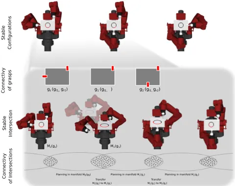
Our problem is an instance ofmulti-modal planning[16], [8], [17], where each different modality corresponds to a different bimanual or unimanual grasp. In developing a planner, we follow a similar strategy of first identifying in-tersection points between different modalities/manifolds, and then planning motion paths to connect them. We illustrate our overall planning approach in Fig. 4 in four layers. We present the details of each layer in Sec. III. Here we present a brief overview and explain how these layers fit together:
• Generating configurations stable against F. Given F
andx, we first identify a candidateQ= (qi)pi=1which
is stable against F, while minimizing the number of regrasps. Q also positions the object at x. The three robot-object configurations shown in the top layer in Fig. 4 is an example output. GivenQ, the lower layers of the planner try to connect each subsequent configuration inQ.
• Connectivity of grasps. Given two subsequent
config-urations generated in the top layer, qi and qi+1, we
identify a sequence of graspsG= (gj)nj=1on the object
to move the grippers from their positions inqi to their
positions in qi+1. The second layer in Fig. 4 shows
an example grasp sequence, connecting the grasps in the first two configurations of the top layer. Note that there are many other possible contact sequences here, possibly going through other intermediate gripper contacts as shown in Fig. 5(c).
• Sampling stable intersections of grasp manifolds.Given
two subsequent graspsgi and gi+1 from the sequence
generated in the layer above, we sample a set of candidate configurations at which the transition fromgi
togi+1 can be performed stably. The configuration in
the middle on the third layer of the Fig. 4 is an example. At the shown configuration, both the unimanual grasp and the bimanual grasp can hold the object stable against gravity, and therefore this configuration is a good candidate to change between two grasp manifolds.
• Connectivity of manifold intersections. Given a set of
configurations at the intersections of sequences of grasp manifolds, this fourth layer performs collision-free and stability-constrained motion planning within the mani-folds to connect the configurations.
The layered structure of our planner enables us to mini-mize the nuber of regrasps at the top layer, but leaves the time-consuming motion planning to the final layer, enabling fast planning time.
III. APPROACH
In this section we describe the details of our planner.
A. Generating configurations stable againstF
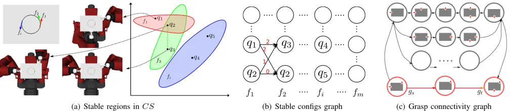
Our planner takes input the sequence of forcesF and the desired object pose x. It starts by generating a sequence of configurations Q such that Q is stable against F, the configurations inQposition the object atx, and the number of regrasps between the configurations inQis minimized.
Given an external force f, we can identify a set of configurations in CS which are stable against this force. In Fig. 5(a), the red, green and blue regions illustrate such sets for forces f1, f2, and fi respectively. Note that there
might be intersections between these stable regions, and a configuration in the intersections is stable against multiple forces; e.g. configuration q2 in the figure is stable against
bothf1 andf2.
Then our problem is to find a sequenceQ= (qi)pi=1 such
(a) Stable regions inCS
2 2
1 0
[image:5.612.61.567.48.158.2](b) Stable configs graph (c) Grasp connectivity graph
Fig. 5. (a) and (b): Planning stable configurations. (c) Planning grasp connectivity.
order. Moreover, we are interested in identifying a sequence Q, such that it will minimize the needs for regrasping.
To create such a sequence of configurations Q, we first sample a set of candidate configurations inCS. To sample configurations that are likely to be stable against a variety of forces, we start by sampling grasps on the object. Using such a sampled grasp g and the desired object position x, we solve the inverse-kinematics problem, which may have many solutions, and sample a single configurationq.
For each sample q, we identify the forces in F that q is stable against (Details of the stability check is explained below in Sec. III-A.1). We then build a directed weighted graph using these configurations as shown in Fig. 5(b). In the graph, the nodes in the ith column are the sampled
configurations that are stable against forcefi. Then we create
a link from every node in ith column to every node in
(i+ 1)thcolumn. We associate each link with a weight using
the number of gripper moves required from one configuration to the other. For example, the weight between the node q2
in the first column and the nodeq2 in the second column is
zero, since the two nodes are the same configurations and no re-grasping is needed. Similarly, if two configurations differ only by one gripper location on the object, the weight for the link between them is set as one. Otherwise, the weight would be two. Note that one can come up with other weighting schemes, e.g., one that takes into account the distance between grasp points.
At this point, our problem in this layer can be formulated as graph search. We want a path that starts from one node in the leftmost column for f1 and ends with a node in the
rightmost column for fm. We can search the graph for an
optimal path. We use Dijkstra’s algorithm, which gives us the sequenceQwith the least number of gripper moves based on the current set of samples. We call this planner the min-regraspplanner.
Building the graph requires knowing the sequence of external forces F beforehand. If the forces are revealed one by one, then the graph can be formed as the next force is specified, and it can be searched greedily. We call this version thegreedy planner.
We provide the pseudo-code for this layer of our planner in Alg. 1 in the procedure P lanStableSequence. On line 1, we generate the graph as described above. One line 2, we search this graph (e.g., Dijkstra’s) to generate Q. Then we iterate over every subsequent pair of configurations inQ (line 4), and try to plan a regrasp between them, which is
explained below. If the regrasp planning fails between two configurations (line 6), we remove the failing link from the graph in Fig. 5(b) (line 7), and re-search the graph to generate a newQ(line 8).
Algorithm 1 Manipulation planning under changing forces P lanStableSequence(F, q0, x):
1: V, E←Sample configs and build graph in Fig. 5(b) 2: Q←GraphSearch(V, E)
3: Q←Appendq0 to beginning ofQ
4: foreach subsequentqi−1 andqi inQ= (qi)pi=1do
5: ti←P lanRegrasp(qi−1, qi) 6: ifP lanRegraspfailedthen
7: V, E←Remove failing edge from graphV, E 8: Go to line 2
9: return(Q= (qi)pi=1,T = (ti)pi=1)
P lanRegrasp(qs, qt):
1: V, E←Sample grasps and build graph in Fig. 5(c) 2: G←GraphSearch(V, E)
3: t←Connect(qs, G= (gi)ni=1, qt) 4: ifConnectfailedthen
5: ifmaximum number of attempts reachedthen
6: returnfailure
7: V, E←Remove failing edge from graphV, E 8: Go to line 2
9: else
10: returnt
SampleIntersection(g, g′) :
1: One ofgand g′must be bimanual. Assumingg. 2: S← {}
3: whileS has less thanmsamplesdo
4: x←Sample pose for object
5: q←Solve IK with object atxand grippers atg 6: ifqis stable against gravity with bothgandg′ then
7: AddqtoS
8: returnS
Connect(qs, G= (g1, g2, ..., gn), qt) : 1: ifn= 1then
2: t←M otionP lan(qs, qt)using graspgn 3: ifM otionP lansuccessfulthen
4: returnt 5: else
6: returnfailure
7: S←SampleIntersection(g1, g2)
8: foreachqinS do
9: t←M otionP lan(qs, q)using graspg1
10: ifM otionP lansuccessfulthen
1) Stability check: Given an external forcef, a configu-ration of the robot-object systemq, and the gripper contacts on the object, we check the stability of the system against f. Given an external force on an object grasped by two cooperating manipulators, the cooperative manipulation lit-erature provides formulations to compute possible torque dis-tributions on the manipulators’ joints. Particularly, Uchiyama et al. provide the symmetric formulation [18], [19], which describes the kinematic and static relationship between the force applied on the object and its counterparts required at the manipulator joints to resist it. This formulation, however, leaves the forces at the grip points unconstrained. In addition to the manipulator joint torque limits, we are also interested in checking whether the grip forces, e.g. the frictional forces between fingers, will be able to resist the external force. This requires the computation of the grasp wrench space [20], which is the space of all external wrenches a grasp on an object can stably resist. For the parallel plate grippers we use in this work, we approximate the grasp wrench space with an axis-aligned box in the six-dimensional force-torque space, i.e. as maximum force and torque limits along each of the three main axes around a grip point as shown in Fig. 3-Right, where[Px, Py, Pz, Rx, Ry, Rz] are these estimated limits.
Imposing this additional constraint onto the symmetric formulation of Uchiyama et al. [18], [19], we have the problem:
JTfg=τ
W fg=−f
|τ| ≤τmax
|fg| ≤fg
max
(1)
where
J=
Jl 0
0 Jr
, fg=
"
fgl fgr
#
, τ=
τl τr
,
τmax=
τl max τr max
, fmaxg =
fgl max fgr max and
• JlandJr are the Jacobians of the two manipulators at
the configuration we are checking the stability;
• fg
l
andfgr
are the forces and torques at the grippers of the two manipulators;
• τl andτr are the vectors of torques acting at the joints
of two manipulators;
• W (sometimes termed the grasp matrix [20], [21], [22])
is a(6×12)matrix mapping the forces and torques at the grippers to a resultant force on the object;
• f is the external force/torque vector on the object; • τmaxl andτmaxr are the torque limits at the joints of the
manipulators;
• fmaxgl andf
gr
maxare our estimates of the maximum force
and torque limits along each of the three main axes of each gripper (i.e. our estimate of the grasp wrench space): fgl
max=f
gr
max= [Px, Py, Pz, Rx, Ry, Rz].
Eq. 1 is a linear programming problem, and can be solved, e.g. using the Simplex method, to see if there are any feasible solutions of the torques at the jointsτ and forces/torques at
the grip pointsfg. If this fails, we consider the configuration unstable against the external force.
B. Connectivity of grasps
Given two subsequent configurations generated in the previous layer, qi and qi+1 in Q, and their corresponding
grasps gs and gt, we identify a sequence of grasps G =
(gj)nj=1on the object to move the grippers fromgstogt. For
example, take the first two configurations in the top row of Fig. 4. The robot must go through a number of intermediate grasps to move between the two grasps on the object (These intermediate grasps serve as alternative to the placement of the object on a support surface, which is the dominant approach used for regrasp planning in the literature).
We start by generating a set of unimanual grasps including the gripper positions ingsandgt and other randomly
sam-pled gripper positions. We then combine these uni-manual grasps to also generate bimanual grasps. Fig. 5(c) represents the connectivity of these grasps as agrasp graph. Each node in the graph is a bimanual or uni-manual grasp. A bimanual and a unimanual grasp is connected if the unimanual grasp is one of the gripper poses in the bimanual grasp. Then, the planner can explore the graph to find a possible path from gstogt, giving us the required sequenceG= (gj)nj=1. This
sequence consists of alternating bimanual and unimanual grasps. Fig. 5(c) highlights in red the shortest grasp sequence. There are other longer grasp sequences to connectgsandgt
as well.
The grasp sequence acts as an abstract plan to guide the search in the lower layers of the planner, and contracts the planning into a concrete and finite group of grasp manifolds. In Alg. 1, the procedureP lanRegraspoutlines this process. On lines 1-2, we build the grasp graph and search it to generate the sequence of grasps G as outlined above. We then try to plan the motion fromqstoqtthrough the grasps
G(line 3). If lower layers of our planner return with a failure to connect two grasps gj and gj+1 in G (line 4), then we
remove the link between these grasps in the grasp graph (line 7), and perform the search again to generate a new sequence of grasps (line 8). If the connection is successful, we return the re-grasp motion to connectqs toqt (line 10).
C. Sampling stable intersections of grasp manifolds
A grasp path provides necessary but not sufficient con-ditions of the connectivity of their corresponding grasp manifolds. To check this connectivity, given two subsequent graspsgandg′, we need to identify configurations at which
In Alg. 1, the procedure SampleIntersection samples m such configurations. To generate one such configuration, we first sample an object pose in the reachable space of the robot (line 4). Then, we solve the inverse-kinematics for the bimanual grasp at the sampled object pose, giving us a configuration q (line 5). We check (line 6) whether both grasps g and g′ are stable against gravity at q, using
the same stability check described in Sec. III-A.1. A stable configuration q is returned as a candidate point connection in the final solution path (line 7).
D. Connectivity of sequence of manifold intersections
Given two configurationsqs andqt, and stable
configura-tions sampled at the intersecconfigura-tions of a sequence of manifolds (i.e., the manifolds of the grasp sequenceG), we search for motion plans that connect qs toqtthrough these manifolds.
In Alg. 1, the procedureConnectimplements this process as depth-first-search. Given a current configuration qs and
a sequence of grasps G= (g1, g2, ..., gn) (where g1 is the
grasp inqs), we sample the intersection of the first two grasps
in the sequence for stable configurations (line 7). We then try to plan a motion from qs to a sampled configuration
q (line 9). Note that this is a motion plan within a single manifold (the manifold of graspg1) and can be generated by
existing closed-chain or single-arm motion planners. These paths, however, must also be stable against gravity, for which constrained motion planners [23], [24] can be used. If the motion plan is successful, the trajectory is returned along with a recursive call to the depth-first-search. Lines 1-6 handle the simple case where qs andqt are already on the
same manifold.
IV. EXPERIMENTS AND RESULTS
In this section, we present experiments to verify the perfor-mance of the proposed planners in terms of minimizing the number of regrasps and planning stable regrasps efficiently. The planners are applied to Baxter developed by Rethink Robotics in an OpenRAVE environment [25]. Baxter has two 7-DOF manipulators, each equipped with a parallel jaw gripper. We used a modified BiRRT planner [26] as implemented in OpenRAVE as the motion planner to connect two configurations.
The planners were tested on two types of forceful opera-tions on a board, drilling and cutting. For all the drilling operations, we randomly changed the magnitude of the drilling forces from10N to15N and we assume the forces are normal to the surface of the board. For the cutting forces, we assume their magnitude varies between 30N to 60N. These operations are instantiated into three categories of tasks, including:
• random-drilling: Each task contains 10 drilling
opera-tions randomly distributed on the surface of the board. An example is shown in Fig. 6;
• tick-drilling: Each task contains 40 drilling operations
along two random line segments meeting at a common point. An example is shown in Fig. 8;
TABLE I
NUMBERS OF REGRASPS(WITH STANDARD DEVIATIONS)OF THREE
PLANNERS ON THREE DIFFERENT TASKS.
Random-drilling Tick-drilling Drilling&cutting
Random 17.6(0.9) 48.7(10.7) 5.8(2.1)
Greedy 7.8(1.9) 4.3(2.4) 3.1(0.8)
Min-regrasp 5.2(0.9) 1.3(1.0) 2.0(0.0)
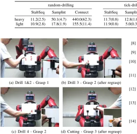
• drilling&cutting: Each example contains four drilling
operations and a cutting operation as shown in Fig. 11. We generate 100 random tasks for each category above. In our experiments, we used a rigid foam board as the object. We also measured the force and torque limits (as explained in Sec. III-A.1) of the Baxter grippers on this ob-ject. Along each axis shown in Fig. 3, we applied increasing amount of forces and torques to find the point when the object started to slide between the parallel plates or when the object rotated more than 5o due to finger link
deforma-tion. We found the limits to be[Px, Py, Pz, Rx, Ry, Rz] =
[13N,40N,13N,0.3N m,0.05N m,0.1N m]. Along the negative Pz direction, the object rests against the palm,
therefore we used a large force limit (100N) in the negative direction ofPz when we solved Eq. 1.
A. Minimizing the number of re-grasps
First, we compared the performance of our planners, min-regraspandgreedy, with a random planner on the number of regrasps. Therandom planner acts as a baseline approach. For the first external force, the random planner samples a random configuration in the configuration space until it finds a feasible one. For any subsequent force, it first checks whether the configuration for the preceding force is still stable. If not, it falls back to random sampling.
Fig. 6. A plan by the min-regrasp planner for a random-drilling task. The dark points indicate the drilling operations applied during the current grasp.
[image:8.612.63.299.325.405.2]Fig. 7. A plan by the greedy planner for a tick-drilling task. The dark points indicate the drilling operations applied during the current grasp.
Fig. 8. A plan by the min-regrasp planner for a tick-drilling task.
Fig. 9. A plan by the min-regrasp planner for drilling on a circular board.
We also counted the number of samples the random planner needed before it found a feasible grasp. On average, the random planner needed 35.8 samples for each external force of the tasks above, showing that planning is necessary and random grasps have little chance of being feasible. Our planners are not limited to grasping rectangular objects. To demonstrate this, we tested the min-regrasp planner on a circular board with a sequence of 40 circular drilling operations. A plan with only two regrasps is shown in Fig. 9.
B. Planning performance
We tested the performance of our planner on light and
heavy objects respectively. We ran the planner on 100 randomly generated tasks for each category as discussed above. Table II shows the average planning time each layer of the planner takes, including time for generating stable
[image:8.612.63.294.442.499.2]sequences (StabSeq for short in Table II), time for generating and searching the grasp graph combined with sampling intersections (SampInt, for short) and motion planning (Con-nect, for short). As the table shows, most time is spent on motion planing, while the time for planning stable con-figuration sequence and sampling intersection is negligible (The planner is set to generate a set of 20 feasible samples for each intersection). Planning for the heavy object takes significantly long time because finding stable regrasping configurations for this object is more difficult.
Fig. 10 shows an example regrasp sequence to regrasp a heavy object. For a light object, the robot can stably grasp and move the object using just a single gripper at most reachable configurations. Thus, mostly, the robot can directly release off and regrasp the object, without the need of reorienting it to intermediate configurations. However, for a heavy object, as discussed in Sec. I, the object may slip down between gripper fingers if the robot directly releases one gripper. That is, the robot needs to move it to intermediate configurations at which one single gripper is enough to keep the object stable. In Fig. 10, the robot first transfers the object to configurations in Fig. 10(b) and 10(d) before releasing one gripper. After releasing, most object weight will be resisted by the forces arising from gripper finger bending as shown in Fig. 10(c) and 10(e), which are much larger than the frictional forces between the object and finger surfaces.
C. Real robot implementation
(a) Start config. (b) Intermed. config. (c) Release (d) Regrasp (e) Release (f) Regrasp (g) Target config.
Fig. 10. Regrasping a heavy object.
TABLE II
PLANNING TIME FOR BOTH HEAVY AND LIGHT OBJECTS. TIMES ARE IN SECONDS. STANDARD DEVIATIONS ARE IN PARANTHESES.
random-drilling tick-drilling drilling&cutting
StabSeq SampInt Connect StabSeq SampInt Connect StabSeq SampInt Connect
heavy 11.2(2.5) 50.1(4.7) 440.0(62.3) 11.7(0.8) 12.8(1.0) 114.4(17.3) 2.2(0.2) 20.6(1.2) 139.1(25.0) light 10.9(2.8) 17.8(1.9) 155.5(11.4) 11.9(0.8) 5.0(0.3) 39.8(8.3) 1.9(0.4) 6.6(0.7) 71(14.1)
(a) Drill 1&2 - Grasp 1 (b) Drill 3 - Grasp 2 (after regrasp)
(c) Drill 4 - Grasp 2 (d) Cutting - Grasp 3 (after regrasp)
Fig. 11. Drilling&cutting task.
V. CONCLUSION ANDFUTUREWORK
We believe the planning system presented here can be a key component in a human-robot collaboration framework. In future work, we aim to include an increasing amount of human comfort factors (e.g. the human kinematics) in planning the collaboration between the human and the robot.
REFERENCES
[1] T. Sim´eon, J.-P. Laumond, J. Cort´es, and A. Sahbani, “Manipulation planning with probabilistic roadmaps,”IJRR, 2004.
[2] T. Lozano-P´erez, J. Jones, E. Mazer, P. O’Donnell, W. Grimson, P. Tournassoud, and A. Lanusse, “Handey: A robot system that recognizes, plans, and manipulates,” inICRA, 1987.
[3] P. Tournassoud, T. Lozano-P´erez, and E. Mazer, “Regrasping,” in ICRA, 1987.
[4] W. Wan and K. Harada, “Developing and comparing single-arm and dual-arm regrasp,”RA-L, 2016.
[5] ——, “Integrated assembly and motion planning using regrasp graphs,”Robotics and biomimetics, vol. 3, no. 1, p. 18, 2016. [6] M. Dogar, A. Spielberg, S. Baker, and D. Rus, “Multi-robot grasp
planning for sequential assembly operations,” inICRA, 2015. [7] P. Lertkultanon and Q.-C. Pham, “A certified-complete bimanual
manipulation planner,”arXiv preprint arXiv:1705.02573, 2017.
[8] T. Bretl, “Motion planning of multi-limbed robots subject to equilib-rium constraints: The free-climbing robot problem,”IJRR, 2006. [9] K. Kosuge and N. Kazamura, “Control of a robot handling an object
in cooperation with a human,” in”RO-MAN”, 1997.
[10] L. Rozo, S. Calinon, D. G. Caldwell, P. Jimenez, and C. Torras, “Learning physical collaborative robot behaviors from human demon-strations,”IEEE Transactions on Robotics, 2016.
[11] F. Abi-Farraj, T. Osa, N. Pedemonte, J. Peters, G. Neumann, and P. G. Robuffo, “A learning-based shared control architecture for interactive task execution,” inICRA, 2017.
[12] R. Luo, R. Hayne, and D. Berenson, “Unsupervised early prediction of human reaching for human–robot collaboration in shared workspaces,” Autonomous Robots, pp. 1–18.
[13] G. J. Maeda, G. Neumann, M. Ewerton, R. Lioutikov, O. Kroemer, and J. Peters, “Probabilistic movement primitives for coordination of multiple human–robot collaborative tasks,” Autonomous Robots, vol. 41, no. 3, pp. 593–612, 2017.
[14] K. W. Strabala, M. K. Lee, A. D. Dragan, J. L. Forlizzi, S. Srini-vasa, M. Cakmak, and V. Micelli, “Towards seamless human-robot handovers,” Journal of Human-Robot Interaction, vol. 2, no. 1, pp. 112–132, 2013.
[15] A. T. Miller and P. K. Allen, “Graspit! a versatile simulator for robotic grasping,”IEEE Robotics & Automation Magazine, vol. 11, no. 4, pp. 110–122, 2004.
[16] K. Hauser and J.-C. Latombe, “Multi-modal motion planning in non-expansive spaces,”IJRR, vol. 29, no. 7, pp. 897–915, 2010. [17] G. Lee, T. Lozano-P´erez, and L. P. Kaelbling, “Hierarchical planning
for multi-contact non-prehensile manipulation,” inIROS, 2015. [18] M. Uchiyama and P. Dauchez, “A symmetric hybrid position/force
control scheme for the coordination of two robots,” inICRA, 1988. [19] ——, “Symmetric kinematic formulation and non-master/slave
coor-dinated control of two-arm robots,”Advanced Robotics, 1992. [20] B. Mishra, J. T. Schwartz, and M. Sharir, “On the existence and
synthesis of multifinger positive grips,”Algorithmica, 1987. [21] C. Ferrari and J. Canny, “Planning optimal grasps,” inICRA, 1992. [22] C. Borst, M. Fischer, and G. Hirzinger, “Grasp planning: How to
choose a suitable task wrench space,” inICRA, 2004.
[23] D. Berenson, S. Srinivasa, and J. Kuffner, “Task space regions: A framework for pose-constrained manipulation planning,”IJRR, vol. 30, no. 12, pp. 1435–1460, 2011.
[24] L. Jaillet and J. M. Porta, “Path planning under kinematic constraints by rapidly exploring manifolds,” IEEE Transactions on Robotics, vol. 29, no. 1, pp. 105–117, 2013.
[25] R. Diankov and J. Kuffner, “Openrave: A planning architecture for autonomous robotics,”Robotics Institute, Pittsburgh, PA, Tech. Rep. CMU-RI-TR-08-34, vol. 79, 2008.