AN ENGINEERING APPROACH TO MODELLING OF
DYNAMIC INSULATION USING ESP-r
Samuel A (*), Imbabi M S (#), Peacock A (%), Strachan P A (*)
(*) ESRU, University of Strathclyde, Glasgow, G1 1XJ, Scotland, UK
(#) Dept of Engineering, Aberdeen University, Aberdeen, AB24 3UE, Scotland, UK (%) James Campbell Architects, Kemnay, AB51 5LN, Scotland, UK
SUMMARY
The use of Dynamic Insulation (DI) can enable recovery of conduction heat loss through a building envelope. This is an active process that allows air to move through the fabric against the temperature gradient. Additionally it promises better indoor air quality, primarily due to filtration properties of the construction material [11]. This paper is concerned with quantifying the energy savings and enhancement of human comfort if this technology is integrated into a building.
To ascertain the impact of the technology on whole-building performance, it is necessary to undertake detailed dynamic modelling. A suitable building and plant simulation computer tool (ESP-r) was employed to do this. A technique for modelling the dynamic insulation was developed and validated against known analytical solutions. A full-size test house was then simulated, in the UK climate, with and without DI. Comparative results show that better thermal comfort and energy savings are possible with the use of DI. The results obtained have been translated into suggestions for best practice.
OBJECTIVE
The objective of this paper is to develop and apply a modelling approach to DI and to quantify associated energy saving and human comfort. The primary concern is identifying, validating and applying a suitable simulation technique for modelling DI.
ESP-r
ESP-r is a transient energy simulation system [5] that is capable of modelling the energy and fluid flows within combined building and plant systems when constrained by appropriate control actions. One or more zones within a building are defined in terms of geometry, construction and usage profiles. These zones are then inter-locked to form a building. Depending on the study, additional model elements can be defined to improve resolution or to model particular features of the building: for example by adding a leakage distribution to enable integrated airflow simulation, a plant network to model air-conditioning plant, or a renewable energy component to model photovoltaic modules. The multi-zone building is subjected to simulation processing against user-defined control. Results analysis modules are then used to view the simulation results. Changes to the model parameters can follow depending on these appraisals.
APPROACH
Two possible approaches were considered.
1. To address the problem at a fundamental level and augment the source code so that ESP-r accepts mass and energy flows through zone constructions representative of the building envelope. This requires the addition of a ventilation term in the finite volume heat balance expressions within the multi-layer constructions, and a modification to the airflow network to allow nodes within constructions.
2. To approximate the dynamic behaviour by dividing the DI wall into a number of fictitious zones. Air can flow from one fictitious zone to another through the wall. By maximising the heat transfer between these zones and the air, the real situation of a continuous flow of air through the wall can be represented by a series of discrete steps.
As a first step, it was decided to adopt the second approach, assuming that good agreement could be reached between analytical solutions and those predicted by the simulation model.
VALIDATION
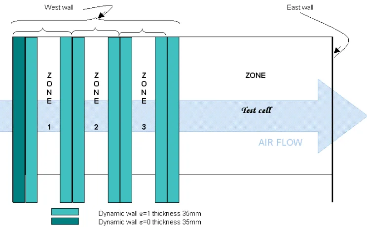
[image:2.595.116.488.499.729.2]This approach was validated against the one-dimensional steady state theory for DI [2,4,6,7,8,9]. A test cell model (fig 1) was constructed in ESP-r. It had air flowing in through the West wall and out through the East wall. The airflow regime was kept quite simple i.e. without complex ductwork etc. The only component included was a constant volume flow rate fan put in the East wall. It was deemed sufficient that this solitary mechanical device would maintain requisite flow rates. The West wall was divided into three fictitious zones. The purpose of these was to facilitate determination of temperature and other parameters inside the wall. It was ensured that these zones did not change the thermal properties of the wall. The emissivity of the outside surface was set to zero to eliminate long wave radiation exchange with the sky; all other surfaces in the fictitious zones of the dynamic wall had emissivity and absorptivity of 1. Other surfaces in the test cell were adiabatic. The convection heat transfer coefficients of the internal surfaces of the wall zones were set to artificially high values (1000W/m2K) to ensure that the temperatures of facing surfaces of the fictitious zones were at the same temperature. The inside temperature of the test cell was controlled to 200C. There were no casual gains (lights, equipment, occupants etc.) and no infiltration; the only air allowed in was through the dynamic wall. In order to control the external conditions to those of the analytical solution, a steady state climate of 00C, zero wind velocity and zero solar radiation was used.
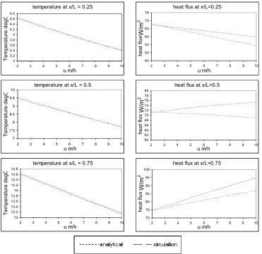
The thermophysical properties of the dynamic insulation were taken from [3]. During the simulation, as air entered fictitious zones 1, 2 and 3 it experienced maximum heat transfer, picking up heat at each interface. The air temperature therefore increased, with a consequent decrease in fabric temperature. Airflow velocity was varied over a typical operational range from 2 to 10 m/h (1.5 to 7.5ac/h) and results analysed to yield the zone temperatures and heat fluxes. These were characteristic of the wall conditions at x/L of ¼, ½, and ¾ where x is the distance through the wall and L is the wall thickness. The results from simulation and the analytical solutions are shown in fig 2. There is good agreement, with predicted temperature within 1% of the analytical solutions and predicted heat flux within 8% up to 8m/h.
[image:3.595.108.479.215.575.2]
Fig 2 Analytical & simulation temperatures & heat fluxes at different air velocities compared
It would be possible to improve the level of agreement by increasing the number of fictitious zones or by distributing more of the zones towards the higher temperature gradients at the inside surface. However, in the interests of simplicity, the above modelling strategy was deemed to be sufficient to achieve representative performance.
CASE STUDY
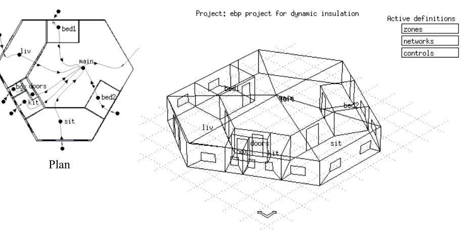
Two similar house models were built in ESP-r (fig 3), one divided into 9 zones and with conventional mechanical extract ventilation. The second was exactly as the first but with 18 additional fictitious zones to model DI. These additional zones were linked, three each, to all the zones with external walls except zone ‘main’ which has an external glazed wall. The designed flow regime accepts air through the external dynamic walls; this air then flows to ‘main’ from where it is drawn into the loft and vented out. For both cases infiltration was assumed to be zero.
temperature at x/L = 0.5
7 7.5 8 8.5 9 9.5 10
2 3 4 5 6 7 8 9 10
u m/h T e m p e ra tu re d e g C
temperature at x/L = 0.75
13 13.2 13.4 13.6 13.8 14 14.2 14.4 14.6 14.8
2 3 4 5 6 7 8 9 10
u m/h T e m p e ra tu re d e g C
heat flux at x/L=0.75
70 75 80 85 90 95 100
2 3 4 5 6 7 8 9 10
u m/h h e a t fl u x W /m_ 2
heat flux at x/L=0.5
60 62 64 66 68 70 72 74 76 78 80
2 3 4 5 6 7 8 9 10
u m/h h e a t fl u x W /m_ 2
heat flux at x/L=0.25
45 50 55 60 65 70 75
2 3 4 5 6 7 8 9 10
u m/h h e a t fl u x W /m _ 2
temperature at x/L = 0.25
3 3.2 3.4 3.6 3.8 4 4.2 4.4 4.6 4.8
2 3 4 5 6 7 8 9 10
Figure 3 Test house as modelled in ESP-r
Airflow rates were determined on the basis of [1], the principal requirement being to provide a minimum of 1ac/h to all living space except for bathrooms and kitchens, where this requirement was a minimum of 3ac/h. Hence different flow rates were required through the different walls. The fact that in most houses the room volume to exterior wall area ratio is different for each room may pose design problems because air velocity through the dynamic wall, being a function of pressure difference, would be the same through all the walls (assuming a homogenous pressure difference distribution throughout the house with respect to the exterior). This would give different air change rates in the different rooms that may differ significantly from building regulations.
Typical occupancy schedules were imposed and casual gains associated. Miscellaneous loads were also added to represent lights and other household equipment. Four options for controlling the heating and ventilation of the test house were considered.
1. Heating is switched on in a room for the period it is occupied only.
2. Heating control is more typical (heating on 06:30~08:30 and 16:30~23:30 weekdays and 07:00~21:00 weekends).
3. Ventilation for DI is always kept on. 4. DI and heating are switched together.
Of the four configurations, two were studied. It was assumed that with an unplanned heating control (option 1) it would be unlikely that ventilation would also be controlled (option 4). Furthermore it was assumed that with planned heating control (option 2), ventilation would also be controlled (option 4). Therefore options 1 and 3 were taken together and so were options 2 and 4. The former was called the occupancy based heating scheme (scheme A) and the latter was termed the fixed heating scheme (scheme B).
A total of six constructions typical of the UK were studied. Two ventilation levels were studied (the first being 1.1 ac/h in living space and 3.5 ac/h in bathrooms and kitchens; the second with airflow rates at 150% of the first: the first ventilation level was also simulated with a 75% efficient air-to-air heat recovery system). Simulation was carried out using UK Example Year climate data for 9~15January, 9~15April, 9~15July and 9~15October, these signifying typical weeks in the four seasons. Results include total heating energy demand, temperature profiles and Percentage People Dissatisfied (PPD) thermal comfort levels.
Plan
SIMULATION RESULTS
Total Heating Energy Required
In general, heating demand increases when ventilation rate increases but with the incorporation of a heat exchanger the energy delivered decreases. For the test house with the design parameters mentioned above, a net saving of 9% without heat recovery and 14% with heat recovery was obtained when DI was incorporated. Some experimental and simplified analyses have reported savings up to 25% [3,10]. However, the figures presented in this paper are for the UK climate and are considered to have more appropriate occupancy and heating schedules. Simulation results predict strong correlation between airflow rate and heating energy required. It was also concluded that a heat exchanger is only useful in the winter months.
Temperature Profiles
Without DI these show a slight decrease – of the order of 10C – in wintertime temperatures when ventilation rate is increased by 50%. This contrasts with the energy consumption, which increases quite dramatically (around 15%), this is due to the increased mass of air that needs to be heated to the set point temperature of 200C. This demands a compromise between heating and ventilation options. Temperatures with DI were higher in winter and lower in summer. A heat exchanger in the dynamic case enhances this effect slightly – of the order of 10C – and increased ventilation rate does not overly affect temperature even though it increases energy demand, because of the same reason as above. The heat exchanger saves around 5% energy in winter.
PPD Profiles
Without DI increased ventilation increases comfort levels in the summer and decreases them in winter. The PPD for both types of ventilation never differs by more than 2%. This suggests that with a ventilation of 150% comfort levels are not changed significantly. With DI and the heat exchanger the detrimental effect on comfort levels in summer time was quite evident from increases in PPD of up to 5%. This fact provides strong impetus to shut off such devices in the summertime. However, in the winter a heat exchanger provides more comfort than DI alone – again of the same order. The comfort levels with DI are better than conventional insulation, apart from a few exceptions, for both summer and winter.
CONCLUSIONS
It must be stressed that DI can only be expected to work at its best with some ideal airflow rate. Such an optimal air velocity exists for every configuration of dynamic construction at which the heating energy consumed is a minimum. For air velocities lower than this value all the conduction heat loss is not recovered and for values higher than this, a heating overhead is incurred in the form of heating increased air mass to the room inside temperature. It should be stated at this point that another important factor, which was not investigated in this paper, is the effect of short wave solar radiation, furthermore this study assumes complete air tightness and in reality some infiltration would be detrimental to DI.
The developed approach is an engineering solution to the problem of modelling DI in that heat is transferred from the construction to the air at discrete points in the fabric and not continuously. This has been shown to be quite a reasonable approximation for typical airflow rates. Percentage errors in both temperature and heat flux show a linear increase with the air velocity over the range studied.
building studied. Furthermore one-sixth of the envelope of the building modelled in the paper was not dynamically insulated.
DI provides better thermal comfort at a lower energy cost than conventional walls and heating systems. DI also decreases the risk of interstitial condensation [6]. With DI, and in the absence of heating, it was found that the building cools down quite quickly - temperature drops as high as 100C over a few hours were seen. This is clearly undesirable so it is advisable that DI be used whilst heating is on. This would cause a lesser overhead on the air extract fan and at the same time allow moisture and CO2 to diffuse to the outside during the period DI is switched off, thus enhancing indoor air quality.
In view of the above discussion DI should be used only with a carefully determined airflow range. Heat exchangers if employed should be shut off in summer.
REFERENCES
1. 6th Amendment to the Technical Standards for Compliance with the Building Standards (Scotland) Regulations 1990 - Part J.
2. Baker P, 2001. The Breathing Wall: A Review of Recent Research and Theory. Client Report no. 16438, Building Research Establishment.
3. Baker P.H, 2003. Dynamic insulation for energy savings and comfort. BRE IP3/03. BRE Bookshop.
4. Dalehaug A, March 1993. Research Report number 53, Dynamic Insulation in walls, Hokkaido Prefectual Cold Region Housing and Urban Research Institute.
5. ESRU, Oct 2003. The ESP-r system for Building Energy Simulation: User Guide Version 10 Series, University of Strathclyde.
6. Samuel A, 2002. Simulation Modelling of Dynamic Insulation as a Means For Energy Saving and Human Comfort, MSc thesis, University of Strathclyde.
7. Taylor B J, Cawthorne D A, Imbabi M S, 1996. Analytical Investigation of the
Steady-State Behaviour of Dynamic and Diffusive Building Envelopes, Building and
Environment, 31(6).
8. Taylor B J, Imbabi M S, 1997. The Effect of Air Film Thermal Resistance on the Behaviour of Dynamic Insulation, Building and Environment, 32(5).
9. Taylor B J, Imbabi M S, 2000. Environmental Design using Dynamic Insulation, ASHRAE Transactions.
10. The Scottish Sports Council. Pore Ventilation: Sports Halls Research Report no.43, Research Report.