7-1964
Tensile test to find endurance limit of strain-ageable
metals
Knud Pedersen
Iowa State UniversityGlenn Murphy
Iowa State UniversityFollow this and additional works at:
http://lib.dr.iastate.edu/ameslab_isreports
Part of the
Metallurgy Commons
This Report is brought to you for free and open access by the Ames Laboratory at Iowa State University Digital Repository. It has been accepted for inclusion in Ames Laboratory Technical Reports by an authorized administrator of Iowa State University Digital Repository. For more information, please contactdigirep@iastate.edu.
Recommended Citation
Pedersen, Knud and Murphy, Glenn, "Tensile test to find endurance limit of strain-ageable metals" (1964).Ames Laboratory Technical Reports. 74.
Abstract
Fatigue curves for steel C-1118 were constructed for room temperature and 100° C from data collected from a number of fatigue tests. The endurance limit of the steel was estimated at the same temperatures from
additional fatigue tests.
Disciplines
Metallurgy
IOWA STATE UNIVERSITY
TENSILE TEST TO FIND ENDURANCE LIMIT OF STRAIN-AGEABLE METALS
by
Knud Pedersen and Glenn Murphy
RESEARCH AND
DEVELOPMENT
REPORT
TID-4500, June 1, 1964
UNITED STATES ATOMIC ENERGY COMMISSION
Research and Development Report
TENSILE TEST TO FIND ENDURANCE LIMIT OF STRAIN -AGEABLE METALS
by
Knud Pedersen and Glenn Murphy
July, 1964
Ames Laboratory at
Iowa State University of Science and Technology F. H. Spedding, Director
IS-929
This report is distributed according to the category Engineering and Equipment (UC -38) as listed in TID-4500, June
1.
1964.r - - - - : - - - -
LEGAL NOTICE - - - ,
This report was prepared as an account of Government sponsored work.
Neither the United States, nor the Commission, nor any person acting on behalf of the Commis sian:
A. Makes any warranty or representation, expressed or implied, with respect to the accuracy, completeness, or usefulness of the information contained in this report, or that the use of any information, apparatus, method, or process disclosed in this
report may not infringe privately owned rights; or
B. Assumes any liabilities with respect to the use of, or for damages resulting from the use of any information, apparatus, method, or process disclosed in this report.
As used in the above, "person acting on behalf of the Commission" includes any employee or contractor of the Commission, or employee of such contractor, to the extent that such employee or contractor of the Commis sian, or employee of such contractor prepares, disseminates, or provides access to, any information pursuant to his employment or contract with the Commis sian, or his employment with such contractor.
Printed in USA. Price
$ .
50 Available .from theIS -929
CONTENTS
ABSTRACT •••••
. . .
.
. . .
. . .
.
. . .
.
.
. .
. . .
.
. .
I.
INTRODUCTION.
... .
II. MATERIAL AND EXPERIMENTAL PROCEDURE
.
... .
A.
Material. . .
.
. . . . . .
.
...
B.
Equipment.
.
.
.
. . .
.
.
. . . .
...
.
...
c.
Testing Procedure. .
.
. . .
...
D.
Calculations.
. . .
.
. ...
III. RESULTS. ... .
IV.
DISCUSSION.
... .
v.
CONCLUSION.
... .
Page5
5
6
6
6
8 99
16
IS-929
TENSILE TEST TO FIND ENDURANCE LIMIT OF STRAIN-AGEABLE METALS
Knud Pedersen and Glenn Murphy ABSTRACT
Fatigue curves for steel C-1118 were constructed for room temper-ature and 100° C from data collected from a number of fatigue tests. The endurance limit of the steel was estimated at the same temperatures from additional fatigue tests.
Cyclic tensile tests were performed on several specimens at each of the two temperatures, with each specimen receiving many cycles of loading and unloading. The proportional limits obtained from the cyclic curves were averaged for each temperature. The value thus obtained for the proportional limit was compared with the endurance limit and there appears to be good agreement.
I. INTRODUCTION
The authors previously investigated the fatigue and tensile proper-ties of zirconium at temperatures ranging from 150 to 750°C, They found that for temperatures up to 450 °C, which is approximately the recrystallization temperature for zirconium, the proportional limit as obtained from a series of tensile cycles fell within the range of determi-nation of the endurance limit obtained from fatigue tests.
similarities in mechanical properties of zirconium and steel were due to
the strain-ageability of the two.
This investigation was undertaken to see if the proportional limit
might also be used to approximate the endurance limit for steel.
II. MATERIAL AND EXPERIMENTAL PROCEDURE
A. Material
The steel was received as
i
in. diameter cold-rolled bars which were cut into 4 in. lengths and machined to the specifications shown in Fig. 1.Since the grain structure appeared uniform no heat-treatment was
per-formed on the specimens.
B. Equipment
The fatigue machines were all of the simply supported rotating beam
type with a motor driving each end to eliminate torsional loads. The
ends of the specimen were free to travel in the axial direction to
elimi-nate shear loads along the test section. Marshall furnace controllers
regulated the temperature in the split type Mpltiple Unit furnaces to
within ± 2 °C.
The number of cycles to failure was recorded on a revolution
counter which indicated every 100 revolutions of the specimen and which
shut off with the motors at the instant of failure.
Because the maximum test temperature was 100°C it was felt
O ....
lt! +.0005·~-.000
TENSILE SPECIMEN
0 2
&81 +.001 · "" -.oooFATIGUE SPECMEN
Fig. l. Specimen dimensions.
-I!UNC TH1
D.
[image:10.599.149.536.172.605.2]The tensile machine was a 60, 000-lb Baldwin-Southwark hydraulic
unit. A linear variable differential transformer (LVDT) transferred the
strain readings from the knife edges to the x-axis of a Mosley Autograf
recorder and another LVDT connected to the Tate-Emery load indicator
transferred the load readings to the y-axis of the recorder. In this
man-ner a direct recording of load vs strain was obtained.
C. Testing Procedure
Half of the fatigue machines were calibrated to 100°C under dynamic
conditions over a 12-h period to observe possible temperature fluctuations.
All of the fatigue machines were balanced while they were running at
test speed. The balancing was done by placing two specimen halves in
the grips and then adding or subtracting lead shot in the load pans until
the specimen halves were aligned when viewed through a telescope. This
procedure eliminated any bending moment on the specimen due to the
weight of the structural numbers and the specimen itself.
The fatigue tests were performed at 4500 rpm. A specimen was
started rotating when the power for the furnace was supplied, but the
bending moment was not applied until after a steady-state temperature
had been reached.
The tensile tests were performed at room temperature and 100
ac
with the latter temperature controlled electronically. The specimens
were loaded slightly beyond the proportional limit and then
unloaded; this process was repeated with continuous recording of the
D. Calculations
The stress caused by the bending moment on the fatigue specimen
was calculated by using the conventional formula S
=
~c
Although thisformula is valid only in the proportional range of stress it was applied
in the non-proportional range for purposes of comparison.
S-N diagrams were made from least-square fitting of the fatigue
data. The curves were assumed to be straight lines on log paper with
the resulting equation of the form ln S
=
m ln N+ ln b, where S is thestress in psi, N is the number of cycles to failure, m is the slope and b
is the intercept, at N = 1, in psi.
The proportional limit was found from an average of the cyclic
ten-sile curves. As a result of strain hardening the proportional limit
increases for the first few load applications until it attains a fairly
con-stant value. Several load applications were made after the limiting
pro-portional limit had been reached and the average was found from these
tests.
The modulus of elasticity was found from the same curves by
aver-aging the slopes.
III. RESULTS
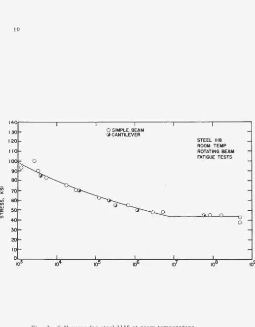
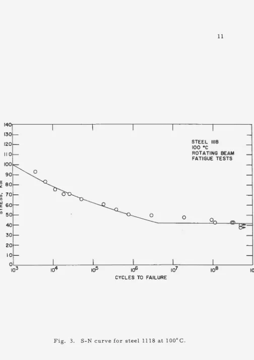
The results of the fatigue tests are presented as S -N curves in
Figs. 2 and 3 for room temperature and 100 °C respectively. Autograf
tracings of stress -strain diagrams from ordinary tensile tests are shown
1401r---~---.r---r---~---~---~
0
0 SIMPLE BEAM (j CANTILEVER
Fig. 2. S-N curve for steel 1118 at room temperature.
STEEL 1118 ROOM TEMP ROTATING BEAM FATIGUE TESTS
[image:13.595.68.585.30.691.2]140r---.---.---.---.---~---~
0
STEEL 1118
roo •c
ROTATING BEAM FATIGUE TESTS
0
0~---~~---~~---~---~~---L
________
_ _ J103
ro4
ro5
ro6
ro7
roB
109
CYCLES TO FAILURE
[image:14.595.82.586.25.738.2]100.---.----.,---~---.---r----.---.---~----~----r---.---~---r----~----,
SPECIMEN No. TT3
STEEL 1118 ROOM TEMP.
~ ~ GAGE LENGTH 1.5
I
TENSILE STRENGTH 82 Ksi
II 12 13 14 15
TOTAL ELONGATION,
[image:15.595.57.680.50.549.2]u;
~en
en1&.1
a::
....
enSPECIMEN NQ TT6 STEEL 1118
1oo•c
GAGE LENGTH t.5iN.
TENSILE STRENGTH 74,500 PSI
O 0 I 2 3 4 5 6 7 8 9 10 II 12 13 14 15
TOTAL ELONGATION IN x 10-3
Fig. 5. Tensile curve for steel 1118 at 100° C. ...
[image:16.593.95.667.70.473.2]100~--~--.---.---,---~--~--~--~--~--~~--~~---r---r---r--~
80
70
"iii 60
~
U) U) I&J 50
a:
...
U)
40
30
20
10
3 4 5 6 7 8 9 10
TOTAL ELONGATION, INCHES X 10-3
SPECIMEN NUMBER T T7
STEEL 1118
ROOM TEMPERATURE
GAGE LENGTH 1.5 INCHES
II 12 13 14
Fig. 6. Autograph recording of cyclic tensile loading at room tempera-ture.
[image:17.599.91.684.50.523.2]70 60 50 (/) lll:
.
(/) (/) 401&.1 a:: ... (/) 30 20 10 0
0 2 3 4 5 6
SPECIMEN NO. TT8
STEEL 1118 100° C
GAGE LENGTH 1.51N.
E=26.5
7 8 9 10
·3 TOTAL ELONGATION, IN x 10
II 12 13 14
Fig. 7. Autograph recording of cyclic tensile loading at 100° C.
15
...
[image:18.597.75.667.106.496.2]of cyclic tensile curves are shown in Figs. 6 and 7.
Table I lists fatigue and tensile properties of the material at the
two test temperatures. The two columns headed "intercept" and "slope"
are for the empirical equations describing the S -N curves, where ln b
is the intercept and m is the slope.
The reason for this investigation was to compare the endurance
limit with the proportional limit as obtained from cyclic tensile testing.
The appropriate columns in Table I shows these results. It appears
that the agreement between the two columns is sufficiently good that
the proportional limit may be used to approximate the endurance limit.
IV. DISCUSSION
When a tensile specimen is cycled through a few cycles of loading
and unloading the proportional limit will gradually increase due to strain
hardening until a fairly constant value has been reached. If the
speci-men is never stressed beyond the proportional limit there will be no
hysteresis loop, and energy being absorbed by the specimen upon
load-ing will be released upon unloadload-ing. If the specimen were stressed in
that manner it could withstand infinitely many cycles, and the endurance
limit would be equal to the proportional limit.
With an increase in the environmental temperature the effect of
annealing will play a role in the fatigue life. It is pas sible that the
rearrangement and cancellation of the dislocations taking place during
Tensile
Temp. strength
oc
ksi25 80. 5
100 74.5
Average Tensile and Fatigue Properties of Steel 1118
Young's Proportional Endurance
Modulus limit limit Fatigue
psix106 ksi ksi ratio
27.6 43.4 44 0.547
25.0 42.1 42 0.564
Intercept loge b
12.126
12.217
Slope -m
0.091
0.102
...
that allows easier movement of the dislocations, would allow the mate-rial to be stressed indefinitely above its proportional limit. With a further increase in temperature, recrystallization will take place and
delay failure of the material, so the amount above the proportional limit which the material could be stressed indefinitely would increase
due to the increased mobility of the dislocations and the increased
rate of recrystallization.
This effect was found in the investigation of zirconium which was carried well beyond the recrystallization temperature. Up to the recrys-tillization temperature the proportional limit and the endurance limit were similar, but above that temperature the endurance limit was greater and became more so with increasing temperatures.
V. CONCLUSION
The endurance limit of steel 1118 may be approximated by the