Development of insulating cross-arms for compact HV lattice tower structures S M ROWLAND*1, R MACLAREN2, I COTTON3,
D CHAMBERS3, V PEESAPATI1, C ZACHARIADES1 1The University of Manchester
2Robimac Associates Ltd 3Arago Technology Ltd
United Kingdom
SUMMARY
There are a number of economic drivers leading to an increase in transmission requirements, and this has become a major issue in the developed and developing world. Many low-cost changes such as re-tensioning existing conductors, re-conductoring, and use of flexible AC transmission systems (FACTS) can give incremental improvements. However, more radical steps are needed to get the greater increase of power transmission required. Up-rating the line voltage is an option, although this requires major spend and upgrade in associated substations and is limited by tower clearance. Clearly rebuilding lines with larger structures is also possible. In addition entirely new lines can be built to reinforce the network. Whilst the latter two solutions are attractive, they are both very costly and incur severe planning delays and uncertainty in many countries.
Insulating composite-cross-arms have been deployed on overhead line power infrastructure for many years and have been seen as a route to tower compaction. Historically the weight of ceramic insulators makes them unsuitable for high voltage lattice tower cross-arm applications, however composite insulators are much lighter. Until recently a limitation to the application of composites has been the compressive buckling resistance required and traditional box-structured cross-arms have not been practical. As a result most composite cross-arms are two-dimensional and designed to move under asymmetrical load conditions, such as wire-breaks.
This paper presents the development of a robust insulating cross-arm design for application on high voltage lattice towers. This uniquely provides a one-for-one replacement of the traditional steel cross-arm design, but removes the need for separate insulators. The motivation of this development are three fold: firstly to develop compact towers, secondly to provide ground clearance solutions for existing lines, and thirdly to allow increases in voltage on existing lines. Using insulating cross-arms can reduce the height of 400 kV towers by over 25%, and voltage upgrade is possible on existing towers.
The mechanical and electrical design phases of the project have used FEA as a mechanical and electrical design tool. Extensive testing of the new cross-arm, including two long-term test sites, has verified the designs. The development of an appropriate testing schedule has been required, since the product is a departure from the standard approach of separating the mechanical and electrical functions of cross-arm and insulator. The proposed design has met the testing regime developed.
KEYWORDS
Insulating cross-arm - ICA - compact tower - overhead line - compaction - upgrade
2 1. INTRODUCTION
The motivation to optimise the use of electricity network rights of way, and the pressure to improve visual amenity of overhead lines is far from new. In 1971 Kimoto et al wrote: ‘In recent years acquisition of transmission right-of-way has become extremely difficult and the need of a most efficient use of right-of-way is being felt keener than ever. It has also become necessary to find means of making towers harmonious, pleasing and unobtrusive to the environment’ [1]. Forty years later the same issues exist.
The introduction of renewable sources to electricity transmission systems, such as wind and solar, has led to an urgent requirement to up-grade networks which until recently have been passively managed. Moreover the likelihood of a move away from gas to electricity for space heating, and from internal combustion engines to electric vehicles is likely to put increasing demands on existing infrastructure. In the developing world the need for rapid and affordable growth has led to a continued rapid expansion of networks.
This paper addresses one solution for improving the capacity of existing lines, and minimising tower structures by replacing metallic tower structures with composite insulating elements: thereby removing the need for separate insulators.
2. HISTORICAL PERSPECTIVE
Just as in the previous section the basic needs are reflected in words written over forty years ago, so the development of composite cross-arms can be traced back fifty years. Two key concepts are particularly useful reference points, and are shown in Figure 1. Firstly, a patent from 1967 [2] suggests the use of an epoxy-glass composite Vierendeel truss structure to provide compressive strength. This concept pre-dates the use of high performance materials and so the ideas were not practical for high voltage application. The work by Kimoto [1] used ceramic technology to construct a high voltage insulating cross-arm However, in this case the weight of the cross-arm required huge strength in the supporting tower – making this version impractical for volume implementation. Both proposals were inhibited in their execution by the materials technology available at the time.
More recently lighter weight solutions have been developed based on glass fibre reinforced composite materials with silicone sheaths and sheds providing electrical insulating properties. While these have been widely accepted as tension and suspension insulators for traditional tower structures, they are inefficient in compression and so have traditionally been limited to two-dimensional structures appropriate for pole routes as shown in Figure 1C. Such designs have been widely and successfully implemented.
3 3. THE BENEFITS OF COMPOSITE CROSS-ARMS
The insulating cross-arms (ICA) described here typically consist of four electrical insulators (two of these being non-cylindrical in nature to give a high strength in mechanical
compression) and replace the steel cross-arms found on typical double circuit overhead line towers. When used in new build tower designs they facilitate a more compact tower
construction, saving cost and giving a number of environmental benefits in terms of reduced visual impact and lower electromagnetic fields.
Using ICAs, a typical UK double circuit transmission tower can be reduced in size as follows:
• A reduction in height of the lowest cross-arm on all suspension towers owing to the
removal of the lowest insulator (at least a 4.5 m saving at 400 kV) while still delivering the required statutory clearance
• A reduction in the phase-to-phase separation of the cross-arms facilitated by the removal of the need to consider the phase-to-earth separation between the conductor and cross-arm
• The elimination of conductor swing on suspension towers
The following example is based on the results of an analysis of the tower size required to accommodate a triple araucaria bundle operating at 400 kV. The general methodology uses National Grid Technical Specifications and the BS EN 50341 standard series for the
calculation of electrical clearances / mid-span spacing. The results of the analysis,
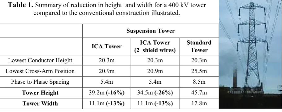
summarised in Table 1, show that a 400 kV design with the same current carrying capacity as an L13 can be delivered using a tower approximately 26% shorter than the standard
requirement (a standard tower with no extension legs over a 450 m span). As the span is reduced, the savings possible through the use of an ICA tower increase given the further reduction that can be made in phase-to-phase clearance.
The reduction in tower height will deliver further benefits due to a reduction in maximum bending moment acting at the base of the tower. In particular this will reduce heavy steel work at the tower base, foundation costs and construction times. A tension tower will also see a significant height reduction given the reduction in phase-to-phase spacing achieved in the ICA design. An increase in height needed above the top cross-arm for the shield wire on the tension tower is factored in to the design of the ICA tower.
Figure 1. Three examples of composite cross-arm design: A) from 1964, a three-dimensional cross-arm (side and plan view) from [2]. B) a 345 kV implementation in Japan
[image:3.595.74.483.76.262.2]4 Table 1. Summary of reduction in height and width for a 400 kV tower
compared to the conventional construction illustrated.
4. MECHANICAL DESIGN AND LABORATORY TESTING 4.1 Design challenge
The primary challenges in developing an insulating cross arm replacement for existing transmission towers are two-fold. Firstly, conventional lattice towers frequently have cross-arms with shallow raking angles of approximately 14 degrees. Under normal operational conditions, this shallow angle results in resolved axial compression loads in the insulators of 4 times the applied conductor load (circa 200 kN under 275 kV heavy ice loading). Secondly, in order to achieve electrical tracking requirements, the profiles have to support the full load without the use of any diagonal bracing, often employed on traditional steel lattice designs.
4.2 Circular to non-circular compression member comparison
Having identified a requirement for slender insulator profiles to be used in compression, the first investigation was a review of performance using conventional circular ‘post’ type
insulators. An analysis of a circular profile necessary to perform a 275 kV upgrade to 400 kV indicated that a 3.4 m long, 60 mm diameter rod would be required with a mass of 73 kg. However, including the silicone this weight is doubles to approximately 150 kg which makes manual handling a challenge requiring a 6 person lift to comply with lifting regulations. From an efficiency perspective it is clear that a more effective design would be a standard column section (or I beam). The critical buckling capacity of any profile can be described by:
2 2
) (KL
EI F = π
where: E is the elastic modulus of material, I is the second moment of area of the profile and KL is the effective length of column. When comparing a circular profile to an I beam the equations for the second moment are:
3 32D Icircle
π
= and ( )
12
1 BD3 bd3
Icolumn = −
It can be seen that an un-optimised square section with dimensions D = 125 mm t = 10 mm is required to match the second moment of area of a solid 120 mm circular profile. Comparing the cross-sectional area illustrates that a 2.4 x weight saving is achievable. However, a hollow square section is not a suitable profile from an electrical perspective. Consequently a high compression strength electrical insulator profile was derived by blending both electrical and mechanical properties to achieve an optimised design as shown in Figure 2.
Suspension Tower
ICA Tower (2 shield wires) ICA Tower Standard Tower Lowest Conductor Height 20.3m 20.3m 20.3m Lowest Cross-Arm Position 20.9m 20.9m 25.5m Phase to Phase Spacing 5.4m 5.4m 8.5m
Tower Height 39.2m (-16%) 34.5m (-26%) 45.7m
5 Figure 2. The optimised insulator strength member cross-section.
4.3 Load lines
The compression load capacity of the insulator profile is highly susceptible to small
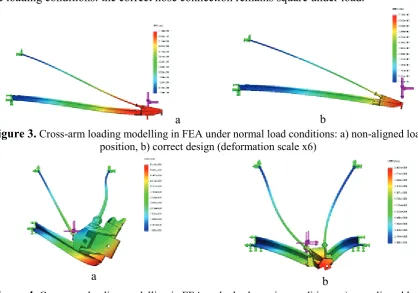
eccentricities in load alignment which result in bending stresses and deflection of the profile. This in turn results in eccentric loading which compounds the bending moment stress and can ultimately result in pre-failures. Careful consideration is therefore required when designing the lines of force extending along the axis of the insulators to the conductor attachment. FEA was performed to gain an understanding of the sensitivity of the conductor positioning.
Figure 3 a) shows a displaced conductor position ∼200 mm short of the end of a poorly designed cross-arm nose. The resulting moment causes the nose to twist, resulting in additional stress in the buckling members. The correctly designed nose (Figure 3b) bends down as expected for a triangulated system of this type. Figure 4 shows the FEA for broken wire loading conditions: the correct nose connection remains square under load.
[image:5.595.89.508.442.735.2]a b
Figure 3.Cross-arm loading modelling in FEA under normal load conditions: a) non-aligned load position, b) correct design (deformation scale x6)
a b
6 4.4 Initial fabricated design and testing
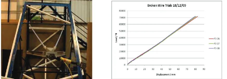
[image:6.595.76.513.211.364.2]To validate the design a full-scale test rig was developed to apply both normal and broken wire conditions. The applied load on the cross arm exceeded the design loads and was held for 5 minutes without any failure in any members. Figure 5 shows the testing of the nose for broken wire conditions. The loading graph for three broken wire trials can also be seen. The graph shows that all three runs produced a straight line up to the full load which indicates there is significant redundancy in the design of the cross-arm. A typical composite member buckling graph shows that as you get near to the buckling load of the member the gradient of the line gradually decreases rather than a sudden failure occurring as seen in steel members.
Figure 5. Broken wire trial. The picture is with a 71.4 kN load applied, and the resulting loading graph is from three broken wire trials.
5. ELECTRICAL DESIGN AND LABORATORY TESTING
The verification of the electrical design has been through means of routine and standardised testing. As in the mechanical design work FEA has been extensively used in development. The design criteria for dry conditions are:
Criterion 1: The average field gradient parallel to the insulator cores is no greater than for conventional composite insulators. At 0.5 mm from insulation surface, the E field magnitudes to be less than 4.5 kV/cm peak.
Criterion 2: The local field on metal fittings to be below the corona inception value of 30 kV/cm peak. This includes all the end connectors, nose cone and stress relief devices [4-6]. Criterion 3: Fields within dielectrics (core and sheds) to be less than 30 kV/cm peak [7].
For the complicated simulation presented by the cross-arm, the modelling was carried out twice: Firstly with a focus on the sheds of the insulators; Secondly concentrating on the metallic end connections, for which finer detailed models are necessary. Examples of the results are shown in Figure 6. Modelling has led to specialised stress control devices for the nose-cone and its proximity [8].
7 Figure 6. FEA results illustrating the detail required in the field modelling.
6. FIELD TESTING AND INSTALLATION TRIALS 6.1 High altitude mechanical trial
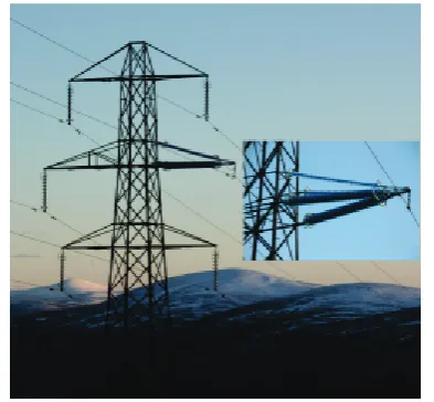
To verify installation techniques and long-term mechanical integrity, a set of ICAs were installed on a de-energised line in the Scottish highlands. The site is 637 m above sea level, with temperatures reaching -20°C and winds exceeding 100 mph (161 km/h). In this trial, the centre cross-arms of one circuit on four adjacent towers were replaced as shown in Figure 7.
Installation was found to be straight-forward, and faster than originally expected. Extensive recordings of snow and ice accretion have given a unique set of records. No degradation of the cross-arms has been identified after the two years’ exposure. Ice and snow accretions were
similar to those levels found on adjacent traditional insulating structures. The trial was terminated after 2 years because the line was due to be permanently taken down.
6.2 Live Trial
A live test site was commissioned in north-east Scotland in May 2012. The main aims of the trial were: to observe the electrical behaviour of the cross-arm and how it changes in relation to the environmental conditions, and to compare the performance of the novel compression insulators with that of the ‘traditional’ tension insulators.
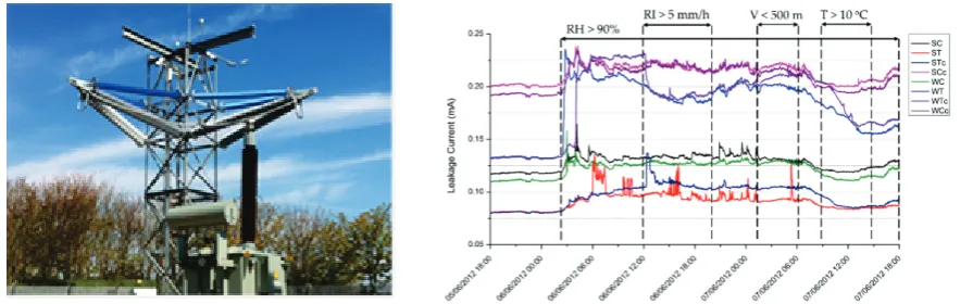
The trial site, located 3.6 km from the coast, accommodates a lattice tower on which two insulating cross-arms have been installed. One cross-arm is facing south while the other is facing west. A 50 kVA transformer provides 231 kV phase-to-ground, equivalent to a 400 kV phase-to-phase system. Leakage current is being continuously measured from each of the eight insulating elements. Furthermore, continuous detailed weather is being monitored. To complement the monitoring instruments, four cameras overlook the cross-arms to capture pollution accumulation, changes in hydrophobicity and snow and ice accretion patterns [9].
At the time of writing, the trial has been running continuously for 18 months. During this period no flashover events have been observed. The results show that the insulating cross-arm performs according to design expectations. The leakage current patterns observed on the
[image:7.595.323.520.285.467.2]8 novel compression insulators are very similar to the ones observed on the industry standard tension insulators. Although the base leakage current profile of the compression members is marginally higher because of their bigger cross-section, their response to changes in the weather conditions is reduced, with smaller fluctuations. The leakage current on the south facing insulators is consistently higher than their west facing counterparts because they have a bigger area exposed to the prevailing wind. All insulators show good self-cleaning properties with their leakage current reducing even after minor periods of precipitation.
7. Conclusion
The composite cross-arm developed offers a cost effective opportunity to increase the capacity of exiting lattice towers, particularly when re-conductoring with high-temperature low-sag conductors. The cross-arm can also be used to build compact towers, reducing the height of a conventional 400 kV tower by over 25% for example.
The new structure has been extensively tested in the laboratory and in the field over a four year period and has performed excellently.
The first installation of these composite cross-arms was successfully completed in Scotland during 2013.
BIBLIOGRAPHY
[1] ‘Insulator cross-arms for 345-kV EHV transmission line’, I Kimoto, K Kito and K Ueno, IEEE Trans PAS, Vol. 90, pp. 756-764, 1971
[2] Patent GB1,034,224: ‘ Improvements in Electric insulators’ 1966
[3] http://www.lappinsulators.de/fileadmin/files/Data_Sheet_Rodurflex_Composite_Insul. _Crossarms.pdf accessed 18.10.12
[4] 'High-voltage engineering', Naidu, M.S. & V. Kamaraju, 2nd edit. 1982, McGraw-Hill. [5] 'High Voltage Engineering and Testing', Allen, N.L., Edited by H M Ryan. 1994. [6] 'High Voltage Engineering'. Kuffel, E., 2000: Newnes.
[7] 'Electric Fields on AC Composite Transmission Line Insulators', Phillips, A.J., et al., IEEE Transactions on Power Delivery, 2008, Vol 23, pp. 823-830.
[8] ‘Electric field computation for a 400 kV composite cross-arm’ Peesapati, V. et al IEEE Conf. on Electrical Insulation and Dielectric Phenomena, Montreal, pp. 790-793, 2012 [9] ‘A Coastal Trial Facility for High Voltage Composite Cross-arms’, C. Zachariades, I.
[image:8.595.76.524.177.317.2]Cotton, S. M. Rowland, V. Peesapati, P.R. Green, D. Chambers and M. Queen, International Symposium on Electrical Insulation. 2012: San Juan, Puerto Rico.
![Figure 1. dimensional cross-arm (side and plan view) from [2]. B) a 345 kV implementation in Japan using ceramic technologies [1]](https://thumb-us.123doks.com/thumbv2/123dok_us/8055496.224621/3.595.74.483.76.262/figure-dimensional-cross-implementation-japan-using-ceramic-technologies.webp)